UNIVERSITÉ DE MONTRÉAL
OXYGEN REDUCTION REACTION ON PALLADIUM-COBALT ALLOY
CATALYSTS FOR POLYMER ELECTROLYTE FUEL CELLS
KENTARO OISHI
DÉPARTEMENT DE GÉNIE CHIMIQUE ÉCOLE POLYTECHNIQUE DE MONTRÉAL
THÈSE PRÉSENTÉE EN VUE DE L’OBTENTION DU DIPLÔME DE PHILOSOPHIAE DOCTOR
(GÉNIE MÉTALLURGIQUE) AVRIL 2012
UNIVERSITÉ DE MONTRÉAL
ÉCOLE POLYTECHNIQUE DE MONTRÉAL
Cette thèse intitulée:
OXYGEN REDUCTION REACTION ON PALLADIUM-COBALT ALLOY CATALYSTS FOR POLYMER ELECTROLYTE FUEL CELLS
présentée : OISHI Kentaro
en vue de l’obtention du diplôme de : Philosophiae Doctor a été dûment acceptée par le jury d’examen constitué de :
M. STUART, Paul, Ph. D., président
M. SAVADOGO, Oumarou, D. d'état, membre et directeur de recherche M.TAVARES, Jason R, Ph. D., membre
DEDICATION
This thesis is dedicated to my spouse Akiko, to my son Waichiro Henry, to my parents Ken-ichi and Emiko, to my sister Megumi and to my grandparents Yukiyasu, Miyoko and Yoshitaka . I also would like to dedicate this thesis to my grandmother, Sue Hori, who passed away in 2006.
ACKNOWLEDGMENTS
I wish to express my sincere gratitude to those who helped me in the completion of this thesis. First of all, I am indebted to my supervisor, Professor Oumarou Savadogo for his kind guidance, valuable support, helpful suggestions, encouragement and confidence in me.
I thank to my colleagues in Ecole Polytechnique de Montreal: Carole Massicotte, Ali Shanian, Frederic Fouda-onana, Teko W. Napporn and Eric Nguwuo Petuenju. I thank you all for working with me during my Ph.D. studies.
I also thank to Professor Professor Shigenori Mitsushima, Professor Nobuyuki Kamiya and Ken-ichiro Ota in Yokohama National University for helping me to grow as a researcher during my bachelor’s thesis.
To Dr. Yuichi Suzuki, Dr. Kunchan Lee and Dr. Akimitsu Ishihara, thank you for believing in me and introducing me to the wonderful world of science.
Lastly, to all of the friends and colleagues at Ecole Polytechnique de Montreal and Yokohama National University, life has been made a much more pleasant ride with your presence.
RÉSUMÉ
L'activité de la réaction de réduction de l’oxygène (RRO) en milieu acide sur les alliages Pd-Co a été étudiée dans ce travail. Les électro-catalyseurs ont été synthétisés par deux techniques : a) La technique de dépôt physique en phase vapeur et b) la technique de réaction de pulvérisation à ultrasons qui a été développée pour la première fois dans notre laboratoire pour préparer directement des électro-catalyseurs supportés sur du tissu ou des feuilles de carbone (GDE) pour des applications de type PEMFC.
Les variations des propriétés électrochimiques telles que les quantités de charge liée à : i) l’adsorption/désorption de d'hydrogène, ii) la formation ou la réduction de la couche d’oxyde en fonction de la composition de l’alliage Pd-Co ont été mises en évidence pour la première fois dans ce travail. Les travaux ont été faits sur des couches minces de Pd-Co préparés par un procédé de pulvérisation sous vide cathodique (PVD). Même si un catalyseur à couche mince ne peut pas être utilisé directement comme électrode de PEMFC fonctionnelle parce que sa surface active est faible, le procédé de pulvérisation cathodique est très utile car la composition chimique de l'alliage et l’aire de surface de l'électrode peuvent être contrôlées avec facilité pour assurer des études fondamentales en électro-catalyse. C’est pour cela, les propriétés électrochimiques fondamentales en électro-catalyse ont été réalisées sur ces couches minces de catalyseurs à base d’alliage de Pd-Co. Ainsi, les quantités de charge des processus électrochimiques sur les alliages de Pd-Co indiqués ci-dessus ont été corrélées aux activités électro-catalytiques de la réaction de réduction de l’oxygène (RRO) en milieu acide. Les bonnes activités électro-catalytiques de la RRO sur des alliages binaires de Pd-Co obtenues dans ce travail sont en accord avec les résultats présentés dans les études antérieures. L’activité électro-catalytique de la RRO sur ces alliages augmente dans le sens suivant : Pd16Co84 < Pd42Co58 < Pd < Pd50Co50 < Pd75Co25 < Pd65Co35. L'alliage Pd65Co35 donne l’activité de la RRO la plus élevée suivie par les alliages Pd75Co25 et Pd50Co50.
Aucunes améliorations d'activité évidentes n'ont été obtenues pour Pd42Co58 et Pd16Co84 qui ont un contenu de Co plus élevé.
Une corrélation linéaire entre les charges d’adsorption/désorption de d'hydrogène et les activités électro-catalytiques de la RRO a été obtenue sur ces alliages de Pd-Co. Les catalyseurs ayant une
teneur en Co plus élevée ont des activités en RRO plus faibles. Par contre aucune corrélation linéaire n’a été observée entre les caractéristiques de l’activité de la RRO et la quantité de charges liée à la formation ou la réduction des oxydes sur les catalyseurs. Les meilleures activités électro-catalytiques pour le RRO on été identifiées sur les alliages ayant un ratio atomique optimisé entre Pd et Co aux alentours de Pd: Co = 3:1.
La méthode de pulvérisation à ultrasons a été développée pour la première fois dans le cadre de ce travail pour la préparation de catalyseurs déposés à l’échelle nanométrique directement sur des supports de feuilles de tissus de carbone commerciaux utilisés (GDE) dans la fabrication des assemblages membranes électrodes pour les piles PEMFC dans notre laboratoire. Cette approche répond bien aux critères d’obtention de catalyseurs de fines particules ayant de grande surface sur la poudre de carbone comme matériaux de cathode pour les piles de type PEMFC. Ceci est d’autant plus pertinent qu’aucune des études réalisées avant n’a réussi à obtenir des particules fines de Pd-Co ayant des dimensions qui soient comparables à celles du catalyseur existant à base de platine à support de carbone (φ2-4 nm).
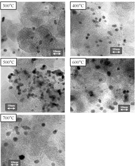
Par conséquent, la mise au point de la méthode de synthèse de catalyseur à base de particules fines de Pd-Co est nécessaire pour mieux utiliser ce catalyseur pour les applications des piles PEMFC. En utilisant cette méthode développée dans ce travail, les catalyseurs de Pt, de Pd et Pd-Co à support de carbone ont été synthétisés et caractérisés pour leur activité en RRO en milieu acide. L’imagerie TEM des échantillons préparés indiquent que la taille des particules dominante de 2,5-4,5 nm. Pour les catalyseurs obtenus. Ce qui montre que cette technique est très utile pour la préparation de catalyseurs à support de carbone à l'échelle nanométrique.
La diffraction des rayons-X (DRX) sur les échantillons fabriqués de Pt a montré que les pics de diffraction sont ceux d’une structure cubique à faces centrées (cfc) de Pt. La DRX descatalyseurs synthétisés de Pd et Pd-Co par réaction de pulvérisation ultrasonique a également indiqué des pics de diffraction d’un système cristallin cubique face centré (CFC). Tous les diffractogrammes des échantillons sont similaires à celui de Pd cfc, mais les pics d'origine Co ne peuvent être observés car le système Pd-Co est une solution solide de substitution, de sorte que certains atomes de Pd sont remplacés par des atomes de cobalt. Ce qui constitue un atout car le système de solution solide est considéré comme étant stable en milieu acide [1].
Aussi nous avons développé dans ce travail une nouvelle technique utilisant la méthode de réaction de pulvérisation à ultrasons pour réaliser dans un même processus la synthèse du catalyseur à support de carbone nanométrique qui est ensuite déposé directement sur l’électrode à diffusion de gaz (GDE) et formé ainsi un GDE catalysé. En utilisant du papier carbone comme comme support de réaction de la pulvérisation à ultrasons tel que décrit ci-dessus, le catalyseur supporté sur de la poudre de carbone à support est directement déposé sur le papier carbone et formé ainsi le GDE catalysé qui peut ainsi être utilisée dans les piles PEFC. Cette technique permet d'économiser certaines étapes importantes comme par exemple la mise en forme de la poudre de catalyseur (préparation de la pâte de catalyseur et son étalement) et de la fabrication du GDE et conduit à un moindre coût de la PEMFC.
Les améliorations obtenues sur l'activité électro-catalytique de la réaction de réduction de l’oxygène en milieu acide sur les catalyseurs de Pd-Co synthétisés par le procédé de réaction de pulvérisation à ultrasons ont été confirmées. Ce résultat est en bon accord avec l’amélioration de l'activité de la RRO de la couche mince synthétisée par PVD. Pour un potentiel donné, le courant de la RRO de Pd3Co1/C et Pd2Co1/C étaient presque les mêmes. Ensuite ce courant diminue de Pd5Co1/C, Pd1Co1/C à Pd/C.
Les résultats ont aussi montré que les catalyseurs à base de Pd ont autour de 45mV/dec de pente de Tafel et de courant d’échange normalisée à la masse de Pd qui est égale à
10-11 mA mg-1. Il est supposé que la cinétique de RRO dans cette région de potentiel est la même pour Pd et les catalyseurs à base de Pd-Co¸ et l'ajout de Co dans le Pd a peu d’effet sur la cinétique de RRO. Nous concluons que la méthode de réaction de pulvérisation à ultrasons avec transducteur piézoélectrique est applicable pour la synthèse du catalyseur à alliage binaire de Pd-Co ou de Pt. L’effet de l’addition de Co au Pd pour former l’alliage Pd-Co sur l’amélioration de l'activité électro-catalytique de la RRO par rapport à celle de RRO sur Pd seul a été confirmé.
Cette étude contribue à l'avancement des connaissances sur les propriétés électro catalytiques fondamentales de la RRO sur les alliages de Pd-Co. En particulier la relation entre la composition de l’alliage en Co et ses activités électro-catalytiques pour la RRO a été établie et une composition optimum de l’alliage qui conduit à une meilleure activité de la RRO a été déduite. Des corrélations ont aussi étudiés réalisées entre la RRO et la quantité de charge liée à
l’adsorption/désorption de l’hydrogène et la formation et à la réduction de l’oxyde sur l’électro-catalyseur.
En outre, la méthode de réaction de pulvérisation à ultrasons, développée dans cette étude, contribue de manière significative et intéressante du point de vue industrielle à un processus intégré de préparation des catalyseurs (alliages de Pd-Co ou Pt) et de fabrication d’électrodes à diffusion de gaz (GDE) catalysées pour les piles PMFC. En plus cette méthode de synthèse mise au point dans ce travail a permis de disposer de catalyseurs ayant des particules de petite taille (φ2-4nm) en alliage Pd-Co ou de Pt qu’il n’a pas été possible d’obtenir de manière homogène et reproductible par les autres méthodes conventionnelles de préparation. Ces résultats sont d’une grade importance pour le développent commercial de la technologie des piles PEMFC parce qu’en plus de permettent l’obtention de particules de tailles optimisées, ils permettent de réduire les étapes de fabrication des assemblages membranes électrodes (MEA) comme par exemple l’étape de mise en forme du catalyseur de la poudre à la pâte et son étalement sur le GDE dans le cas des méthodes conventionnelles. Alors que dans l’approche de ce travail c’est un dépôt direct du catalyseur sur le GDE au fur et à mesure qu’il est fabriqué. En plus, notre approche permet de réduire leur coût de fabrication et augmente la fiabilité du MEA suite à la réduction des étapes de sa fabrication.
ABSTRACT
The Oxygen Reduction Reaction (ORR) activity in acid medium on Pd-Co was studied in this work. The catalysts were synthesized by two techniques; physical vapor deposition technique and ultrasonic spray reaction technique. The last technique was developed for the first time in our laboratory for the supported electro catalyst preparation and direct deposition onto the carbon paper or gas diffusion electrode the for PEMFC applications. The electrochemical properties such as the amount of hydrogen adsorption/desorption, the oxide formation/reduction of Pd-Co alloy catalyst have not been sufficiently studied before. Therefore these electrochemical properties were investigated by using the Pd-Co thin films prepared by sputtering method. A thin film catalyst cannot be directly used as an electrode of working PEMFCs, however the sputtering method is very useful since the chemical composition of alloy and surface area of the electrode can be controlled easily. Thus the fundamental electrochemical properties such as the amount of hydrogen adsorption/desorption, oxide formation/reduction and oxide reduction peak position on thin films of Pd-Co alloy, Pd and Pt catalysts were determined and their correlations to ORR catalytic activities in acid medium were studied. Enhancements of the catalytic activities for ORR by Pd-Co binary alloys were found to be in agreement with results obtained in previous studies. The electro catalytic performance of the ORR on the various electrodes studied here is: in the order Pd16Co84 < Pd42Co58 < Pd < Pd50Co50 < Pd75Co25 < Pd65Co35. This result clearly shows that alloying Pd with a specific composition of Co enhances significantly the electro-catalytic properties of the ORR on Pd-Co alloys in comparison to Pd alone. Pd65Co35 alloy exhibited the highest ORR activity followed by Pd75Co25 and Pd50Co50 alloys. No obvious activity enhancements were found for Pd42Co58 and Pd16Co84, which have higher Co content. A linear correlation between hydrogen charges and ORR catalytic activities on Pd-Co alloys was obtained. Catalysts having more Co content have lower ORR activities. With regard to the correlation between the amount of oxide formation/reduction and ORR activities, no linier correlation was found. However the results of this work indicated that the optimized atomic ratio between Pd and Co for ORR in acid medium was found to be around Pd:Co = 3:1.
Ultrasonic spray reaction method was developed for the first time in our laboratory for carbon supported nano-scale catalyst for PEMFC application. Fine catalyst particles supported on high surface area carbon powder are required to apply the catalyst as the PEMFC cathode materials for
the commercialization, but none of the studies done before were able to successfully obtain the Pd-Co fine particles which are comparable with the existing carbon supported platinum catalyst (φ2-4nm). Therefore the establishment of the catalyst synthesis method for Pd-Co fine particles are required to use the catalyst for PEMFCs. By using this method established in this study, carbon supported Pt, Pd and Pd-Co catalysts were synthesized and characterised for ORR activity. TEM images indicate that this technique is very useful for preparing carbon supported nano-scale catalysts having the dominant particle size of 2.5-4.5 nm. XRD showed diffraction peaks consistent with face-centered cubic (fcc) structure for Pt. XRD of the synthesized Pd and Pd-Co catalysts by ultrasonic spray reaction also indicated fcc crystal system. All diffractograms of the samples are similar to the structure of fcc Pd, but the Co-origin peaks cannot be found. The Pd-Co system is substitutional solid solutions where some Pd atoms are replaced by Co atoms. The solid solution system is considered to be stable in acid media [1].
We developed this new technique of the ultrasonic spray reaction method not only for nano-scale carbon supported catalyst synthesis but also fabricate directly catalyzed GDE. By using carbon paper as a filter of ultrasonic spray reaction method as described above, carbon supported catalyst are directly deposited onto the carbon paper. It directly forms catalyzed GDE. This technique saves some step of the GDE fabrication and will leads lower cost of PEMFC.
Catalytic activity enhancements of ORR for the synthesized Pd-Co catalysts by ultrasonic spray reaction method are confirmed. This result has good agreement with the ORR activity enhancement of the thin film synthesized by PVD. For a given potential, the ORR current of Pd3Co1/C and Pd2Co1/C were almost the same and show the highest values among the values of all the other alloys. After, the value of the current decreases from Pd5Co1/C to Pd1Co1/C and Pd/C. All Pd based catalysts have around 45mV/dec of tafel slope and Pd mass corrected exchange current around 10-11 mA mg-1. It is assumed that the ORR kinetics in this potential region are the same among the Pd and Pd based catalysts and the addition of Co into Pd have small effect on the ORR kinetics. We conclude that ultrasonic spray reaction method with piezoelectric transducer is applicable for Pd-Co binary alloy catalyst synthesis and the activity enhancement effect caused by alloying with Co was confirmed on the synthesized catalyst by this technique.
This study contributes to the advancement of the knowledge of fundamental properties of Pd-Co alloy catalysts and their correlations to the oxygen reduction reaction activities. In addition, the ultrasonic spray reaction method developed for the first time in this study introduces a new easy and low cost Membrane Electrode Assembly preparation significantly to an industrial fabrication process of method of preparation of catalyzed gas diffusion electrodes for PEMFCs. The synthesis method of small particle size (φ2-4nm) Pd-Co alloy catalysts were not possible to be obtained by using the existing conventional methods. However this work has achieved the synthesis of the fine particle catalysts supported on carbons by using the ultrasonic spray reaction method. These results will contribute significantly in the development of PEMFCs based on Pd-Co alloy catalysts in the future.
TABLE OF CONTENTS
DEDICATION ... III ACKNOWLEDGMENTS ... IV RÉSUMÉ ... V ABSTRACT ... IX TABLE OF CONTENTS ... XII LIST OF TABLES ... XV LIST OF FIGURES ... XVI LIST OF ABBREVIATIONS ... XX
CHAPTER 1 INTRODUCTION ... 1
CHAPTER 2 LITERATURE REVIEW ... 3
2.1 Fuel cells and oxygen reduction reaction ... 4
2.1.1 Basic reactions ... 4
2.2 The oxygen reduction reaction (ORR) ... 10
2.2.1 Electrode kinetics of the oxygen reduction reaction ... 12
2.2.2 Electrode kinetics of ORR at platinum surface ... 17
2.3 Catalysts materials for the ORR ... 19
2.3.1 Platinum and platinum-alloys materials ... 19
2.3.2 Palladium and palladium-alloy materials ... 20
CHAPTER 3 OBJECTIVES AND METHODOLOGY ... 27
CHAPTER 4 SUMMARY OF THE WORKS ... 30
4.1 New Method of Preparation of Catalyzed Gas Diffusion Electrode for Polymer Electrolyte Fuel Cells Based on Ultrasonic Direct Solution Spray Reaction ... 30
4.1.2 Experimental ... 32
4.1.2.1 Catalyzed GDE preparation ... 32
4.1.2.2 XRD analysis ... 35
4.1.2.3 TEM analysis ... 36
4.1.2.4 Electrochemical Measurement ... 36
4.1.3 Results and Discussion ... 37
4.1.4 Conclusions ... 43
4.2 Electrochemical investigation of Pd-Co thin films binary alloy for oxygen reduction reaction in acid medium ... 44
4.2.1 Introduction ... 44
4.2.2 Experimental conditions ... 47
4.2.2.1 Chemicals ... 47
4.2.2.2 Electrode preparation and characterization ... 47
4.2.2.3 Electrochemical analysis ... 48
4.2.3 Results and Discussion ... 48
4.2.4 Conclusion ... 64
4.3 Correlation between the Physico-chemical Properties and the oxygen reduction reaction electro catalytic activity in acid medium of Pd-Co alloys synthesized by Ultrasonic Spray Method ... 66 4.3.1 Introduction ... 66 4.3.2 Experimental ... 72 4.3.2.1 Catalyst synthesis ... 72 4.3.2.2 Electrode preparation ... 73 4.3.2.3 XRD analysis ... 74 4.3.2.4 TEM analysis ... 74
4.3.2.5 XPS analysis ... 75
4.3.2.6 Electrochemical measurement ... 75
4.3.3 Results and Discussion ... 75
4.3.4 Conclusion ... 91
CHAPTER 5 GENERAL DISCUSSION ... 92
CONCLUSION AND RECOMMENDATIONS ... 97
LIST OF REFERENCES ... 99
LIST OF TABLES
Table 2.1 Characteristics of typical fuel cell systems ... 5
Table 2.2 Oxidation reactions of various fuels and their thermodynamic data at 25ºC. ... 5
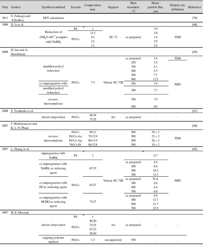
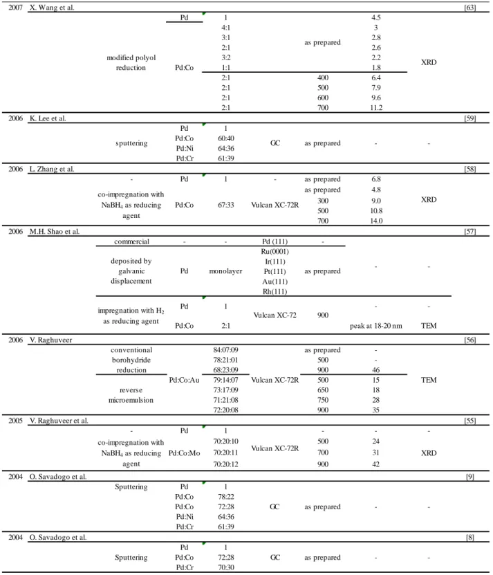
Table 2.3 Previous work on Pd-Co electrocatalysts for ORR. ... 25
Table 4.1 Chemical composition of the thin film electrode synthesized by PVD (atomic %) ... 49
Table 4.2 Tafel slopes in low and high currenty density regions and calculated exchange currents densities of Pt, Pd and Pd-Co catalysts fabricated by sputtering method. ... 58
Table 4.3 Mean particle size of the catalysts synthesized by ultrasonic spray reaction method analyzed by XRD and TEM ... 76
Table 4.4 Tafel slopes in low and high currenty density regions and calculated exchange currents densities of Pt, Pd and Pd-Co catalysts fabricated by sputtering method. ... 88
Table 5.1 Comparison of the ORR mass activity ... 95
LIST OF FIGURES
Figure 2.1 Schematic of working PEMFC ... 6
Figure 2.2 Current-Voltage characteristics and thermodynamic properties of actual PEMFC... 10
Figure 2.3 Bagotskii et al.’s schematic for the oxygen reduction. ... 13
Figure 2.4 Bagotskii et al.’s schematic for the oxygen reduction. ... 14
Figure 2.5 Anastasijevic et al.’s schematic for the oxygen reduction. ... 14
Figure 2.6 Models of O2 adsorption on electrode surfaces. ... 17
Figure 2.7 Relationship between logarithm of current density (i) [30] and overvoltage (η) [31] for ORR on various noble metal cathodes. The current density was obtained at 0.8 V vs. RHE in 85% H3PO4 (25°C). The overvoltage was obtained at i=10-5 A cm-2 in 0.5 M H2SO4 (25°C). ... 19
Figure 4.1 Outlines of two different techniques for the gas diffusion electrode preparation; one of the ordinary methods and the ultrasonic spray method. ... 34
Figure 4.2 Schematic of Home made catalyst maker with ultrasonic spray device. (1)-ultrasonic spray unit and control system, (2)-solution spray chamber, (3)-quartz tube reactor, (4)-furnace, (5)-filter (gas diffusion layer), (6)-main control panel, (7)-thermocouple located at top-end of the heater, (8)-pressure gaze and control unit, (9)-cold trap system, (10)-heavy duty vacuum pump. ... 35
Figure 4.3 Photos of the synthesized GDE by use of the direct solution spray reaction method; a and b are after and before the synthesis, respectively. ... 37
Figure 4.4 Cross section scanning electron microscopic (SEM) image of a GDE synthesized by use of the direct solution spray reaction method ... 37
Figure 4.5 X-ray diffraction pattern of the catalysts on GDE synthesized at 300 through 700°C. Peak positions for Pt metal are indicated by Miller indices. ... 38
Figure 4.6 Relation between thermal treatment temperatures in the tube reactor during catalyst synthesis and d-spacing of Pt(111). ... 39
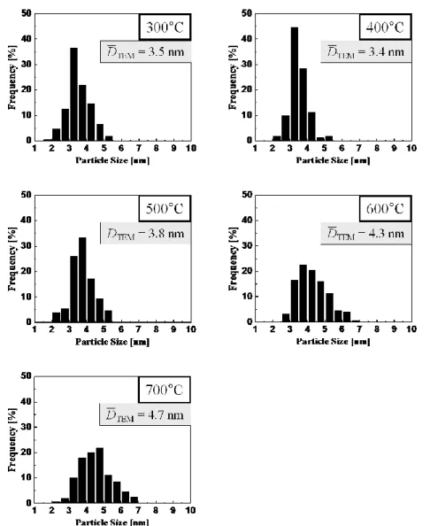
Figure 4.8 Histograms of Pt nano-particle size distributions and mean particle sizes obtained from TEM micrographs. ... 41 Figure 4.9 Oxygen electro-reduction properties of GDEs synthesized at different temperatures.
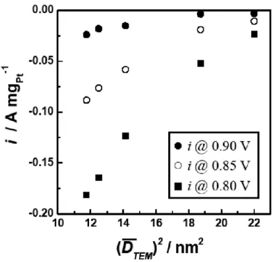
The currents are normalized to Pt unit mass. ... 42 Figure 4.10 The current at various potentials and its dependence to a squaring value of the mean
particle diameter. ... 43 Figure 4.11 Cyclic voltammograms of Pd-Co alloy, Pd and Pt electrodes in 0.05M H2SO4 and
nitrogen purge at 298.15K. ... 50 Figure 4.12 Cyclic Voltammograms of Pd75Co25, Pd100 and Pt100 electrodes in 0.05M H2SO4 and
nitrogen purge at 298.15K. ... 51 Figure 4.13 Dependence of the hydrogen charge as a function of electrode composition ... 53 Figure 4.14 Dependence of the oxide formation charge as a function of electrode composition .. 53 Figure 4.15 Dependence of the amount of oxide reduction as a function of electrode composition ... 54 Figure 4.16 Dependence of the ratio Q (oxide formation)/(Oxide reduction) as a function of
electrode composition ... 55 Figure 4.17 Dependence of the peak position of oxide reduction wave as a function of electrode
composition ... 56 Figure 4.18 Polalization curve for ORR of Pt, Pd and various composition of Pd-Co alloy
catalysts at 273.15 K. ... 57 Figure 4.19 Tafel plot for the Pd-Co, Pd and Pt electrocatalysts at 273.15 K. ... 57 Figure 4.20 Slow scan voltammetry (3 mV/s) for the ORR on Pd64Co35 electrode at various
rotation speed with RDE. ... 60 Figure 4.21 Koutecky–Levich plot of the Pd-Co, Pd and Pt electrocatalysts at 0.4V vs. RHE ... 60 Figure 4.22 Proposed mechanism for the oxygen reduction reaction on Palladium– Cobalt
Figure 4.23 Dependences of the ORR currents at0.800, 0.825 and 0.850 V as a function of electrode composition ... 62 Figure 4.24 Dependence of the ORR currents at 0.800, 0.825, 0.850 V as a function of hydrogen
charge ... 63 Figure 4.25 Dependence of the ORR currents at 0.800, 0.825, 0.850 V as a function of oxide
formation charge ... 63 Figure 4.26 Dependence of the ORR currents at 0.800, 0.825, 0.850 V as a function of the
amount of oxide reduction ... 64 Figure 4.27 Catalyst synthesis procedure by ultrasonic spray reaction method ... 73 Figure 4.28 XRD patterns of the carbon support, Pd and Pd-Co alloys synthesized by ultrasonic
spray method at various compositions. ... 77 Figure 4.29 Phase diagram of Pd-Co system obtained from FactSage software. ... 78 Figure 4.30 TEM images of synthesized catalysts; a) Pd/C, b) Pd5Co1/C, c) Pd3Co1/C, d)
Pd2Co1/C, e) Pd1Co1/C. ... 79 Figure 4.31 TEM Selected Area Electron Diffraction (SAED) pattern taken from synthesized
catalysts; a) Pd/C, b) Pd5Co1/C, c) Pd3Co1/C, d) Pd2Co1/C, e) Pd1Co1/C. ... 80 Figure 4.32 Particle Size Distribution Histogram of Palladium-Cobalt alloy catalysts obtained
from TEM images. ... 81 Figure 4.33 Box-and-whisker diagram indicating sample minimum, lower quartile (25%), median
(50%), upper quartile (75%), and sample maximum for the five different samples. The × mark indicates the mean particle size calculated. ... 81 Figure 4.34 Particle size comparisons between this study and literatures ... 83 Figure 4.35 XPS spectra obtained from synthesized Pd/C and Pd-Co/C catalysts for Pd 3d core
level and Co 2p core level. ... 84 Figure 4.36 Cyclic voltammograms of commercial catalysts (E-TEK) and various compositions
of carbon supported Pd-Co catalyst synthesized by ultrasonic spray reaction method in nitrogen purged 0.05 mol.dm–3 H2SO4 at 298K ... 85
Figure 4.37 Slow scan voltammograms of commercial catalysts (E-TEK) and various compositions of carbon supported Pd-Co catalyst synthesized by ultrasonic spray reaction method in oxygen purged 0.05 mol.dm–3 H2SO4 at 298K. ... 86 Figure 4.38 Comparison of current densities at various potentials of commercial catalysts (E-TEK) and synthesized Pd and Pd-Co catalyst synthesized by ultrasonic spray reaction method. ... 87 Figure 4.39 Tafel slopes of commercial catalysts (E-TEK) and synthesized Pd and Pd-Co catalyst
by ultrasonic spray reaction method in oxygen p urged 0.05 mol dm–3 H2SO4 at 298K. ... 88 Figure 4.40 Koutecky–Levich plot of Pt/C, Pd/C and Pd65Co35/C at 0.4V vs. RHE. ... 90
LIST OF ABBREVIATIONS
AES Auger Electron Spectroscopy AFC Alkaline Fuel Cell Fuel Cell
BE Binding Energy
CV Cyclic Voltammetry
DMFC Direct Methanol Fuel Cell
EELS Electron Energy Loss Spectroscopy EMF Electromotive Force
FC Fuel Cell
FRA Frequency Response Analyzer
GC Glassy Carbon
GDE Gas Diffusion Electrode GDL Gas Diffusion Layer
GS Galvanostat
HOR Hydrogen Oxidation Reaction MCFC Molten Carbonate Fuel Cell
MEA Membrane and Electrode Assembly NHE Normal Hydrogen Electrode
ORR Oxygen Reduction Reaction PAFC Phosphoric Acid Fuel Cell
PEM Polymer Electrolyte Membrane (Proton Exchange Membrane)
PEMFC Polymer Electrolyte Membrane Fuel Cell (Proton Electrolyte Membrane Fuel Cells
RHE Reversible Hydrogen Electrode SEM Scanning Electron Microscope SHE Standard Hydrogen Electrode SOFC Solid Oxide Fuel Cell
SSL Slow Scan Voltammetry
STEM Scanning Transmission Electron Microscope TEM Transmission Electron Microscopy
THE Trapped Hydrogen Electrode USPR Ultrasonic solution spray reaction XPS X-ray Photoelectron Spectroscopy XRD X-ray Diffraction
CHAPTER 1
INTRODUCTION
Since the time of the industrial revolution, the world’s energy needs have been growing exponentially and will keep growing in the future. Fossil fuels such as coal, oil, natural gas have been used as the primary source of energy over the past 260 years, but the reserve will be depleted in the not too distant future and use of the fuels raise environmental concerns. In order to overcome the crisis by fossil fuels depletion, alternative energy resources have to found and they should be cost-effective, renewable, sustainable and environmentally friendly.
A fuel cell is a promising energy-conversion device that is more efficient and more environmentally friendly than existing combustion-based systems. Fuel cell is an electrochemical energy conversion device that converts chemical energy into electrical energy directly. Since there is no combustion or moving parts, the theoretical efficiency of fuel cells can be approximately 80% while that of combustion processes is limited to about 20% at low temperature below 100°C. Polymer electrolyte membrane fuel cells (PEMFC), which are considered in this study, usually take hydrogen, methanol or other small organic molecules as a fuel. In case of hydrogen-oxygen type fuel cells, it produces only water and heat. Therefore this system is very friendly to environment. Replacing fossil fuels with other sustainable resources plays a very important role in both environmental and economical terms. The fed hydrogen gas or small organic molecules, for example methanol and ethanol, are electrochemically oxidized at anode and the generated proton and electron react with oxygen gas fed into cathode and form water molecule (oxygen reduction reaction).
The Oxygen reduction is considered to be one of the most important electrocatalytic reactions because of its role in electrochemical energy conversion, several industrial processes, and corrosion. Consequently, for many years it has been the focus of electrochemical interest. Platinum has been the best catalyst for the ORR for over 170 years since Christian Friedrich Schoenbein and William Robert Grove reported the first study on fuel cells [2]. However, this does not mean that platinum is the optimal material for fuel cell application, because of its fundamental catalytic property limitations, very high cost, limited reserves, and political issues. Therefore a future commercialization of PEMFCs cannot be based solely on platinum-based technologies. It is essential to develop a catalyst having higher ORR catalytic activity and high cost-performance for the future.
The first study on Pd-based alloy materials was demonstrated by the research group of O. Savadogo in 2004 for PEMFC cathode catalysts [3]. The fact that palladium potentially has a high catalytic activity for ORR next to platinum and that alloying with the 3d-transition metal enhances the catalytic activity of the base element suggests that alloying can also enhance the electrocatalytic activity of palladium electrode. Palladium-Cobalt binary alloy was selected in this study, since Pd-Co exhibited the best ORR catalytic activity between Co, Cr, Ni in our previous study [3]. However since Pd-Co alloy is very new as a cathode material for PEMFCs, fundamental aspects on the Pd-alloy electro-catalysts were not deeply studied yet, so their physical, chemical and electrochemical properties were needed to be investigated. In addition, it’s very important to cover from fundamental research to applications to contacts with industry. Hence not only the fundamental studies, but also catalyst synthesis process for carbon supported Pd-Co alloys which allows to use for the PEMFC cathode materials directly need to be developed.
Fine catalyst particles supported on high surface area carbon powder are essential factor to apply the catalyst as the PEMFC cathode materials for the commercialization. However I found that the conventional synthesis processes which has been used for carbon supported catalyst were not optimal methods. None of the studies done before were able to successfully obtain the Pd-Co fine particles which are comparable with the existing carbon supported platinum catalyst (φ2-4nm). A catalyst maker with ultrasonic piezo-electric transducer was built in our laboratory to carry out an catalyst synthesis process of ultrasonic spray reaction method. This technique was firstly developed by Uematsu et al. [4-6] to prepare fine composite catalysts of Ni/TiO2, Ni/Al2O3, Pd/ZrO2, Ru/Al2O3, and Ru/TiO2. The technique demonstrated excellent results for preparing multi-components composites on oxide catalyst supports. The obtained catalysts had strong interaction among the components because the composites were formed from droplets of a homogeneous solution in a quick-heating process. This technique was very unique and never been studied for PEMFCs, I’ve investigated the feasibilities of the technique for the catalyst synthesis process in this study.
CHAPTER 2
LITERATURE REVIEW
The anode of the fuel cell oxidizes H2 while the cathode reduces O2 according to Reactions Eq. 2.1 and Eq. 2.2, respectively. The overall reaction is given as Reaction Eq. 2.3.
Anode reaction 2 2 e Eq. 2.1 Cathode reaction O2 e 2 2O Eq. 2.2 Overall reaction 2 2 O2 2 2O Eq. 2.3 Both anodic and cathodic reactions are catalyzed, typically with highly dispersed Pt on a porous carbon support. However the rate of the oxygen reduction reaction (ORR) is several orders of magnitude less than the rate of the hydrogen oxidation reaction (HOR). To counter this unavoidable constraint, the Pt loadings on the fuel cell cathode typically approach 40% or more, which dramatically increases the fabrication cost of fuel cells. Despite the high Pt loadings, the slow ORR often requires over potentials of 0.3 V – 0.4 V to achieve acceptable current densities and results in decreased efficiency.
Currently, Pt loadings for PEMFCs are between 0.6 and 0.8 mg-Pt/cm2 (corresponding to 0.85-1.1 g-Pt/kW @ 0.65 V) which is a significant improvement achieved over the last 15 years. However, Pt loading should be reduced at least five times to meet projected requirements for large-scale commercial usage (< 0.2 g-Pt/kW @ > 0.65 V) [7]. Gasteiger et al. state that two strategies to meet these requirements are i) increasing MEA power densities by reducing mass-transport-limitations at high current densities and ii) reducing Pt loading in PEM electrodes to 0.15 mg-Pt/cm2. These requirements are necessary both due to cost and Pt supply considerations.
Currently, Pt trades at well over $1,000/troy oz., and the cost is expected to increase in the next decade as demand for Pt as a catalyst, inert coating, and precious metal rises.
Decreasing Pt loadings in PEM electrodes requires both greater dispersions of Pt (the fraction of surface Pt atoms/total Pt atoms) and greater site-specific oxygen reduction activity. To distinguish these two enhancements, Gasteiger et al. [7] have suggested a benchmark of 0.32 to 0.64 A/mg-Pt @ 0.9 V and 00 to 800 μA/cm2-Pt @ 0.9 V for mass and site specific activity, respectively. To reach these two goals, it is necessary to develop a new electrocatalysts and/or new synthesis techniques that provide high catalyst dispersion, ORR activity, and stability.
2.1 Fuel cells and oxygen reduction reaction
Fuel cells are expected to be one of the major clean energy sources in the near future. However, the slow kinetics of the electrocatalytic activity of the oxygen reduction reaction (ORR) and the high loading of novel metal cathode materials are the urgent issues to be addressed. This is very important because they determine the efficiency and the cost of this energy source. This study is on the material issues relating to the effect of the electrocatalyst composition on the Oxygen Reduction Reaction (ORR) in fuel cells.
2.1.1 Basic reactions
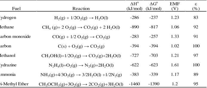
Fuel cells are electrochemical devices that convert chemical energy of fuels directly into electrical energy, thereby promising power generation with high efficiency and low environmental impact. They provide the cleanest and most efficient technologies for generating electricity. They are not limited by thermodynamic limitations such as Carnot efficiency since the system avoids the intermediate steps of producing heat and mechanical work which are typical of conventional methods of power generation. Fuel cells also avoid combustion, hence they produce power with minimal pollutants. As long as the reductant (fuel) and oxidant are provided continuously, fuel cells continue to generate electricity. Hydrogen, methanol, and hydrocarbons are various fuels commonly used in fuel cells. Oxidants used are generally air or oxygen. Several types of electrolytes can be used in fuel cells such as acids, bases, solid and polymer electrolytes, molten salt and conductive ceramics. Some typical fuel cell systems are shown in Table 2.1 Characteristics of typical fuel cell systems Characteristics of typical fuel cell systems. In addition, Table 2.2 Oxidation reactions of various fuels and their thermodynamic data at 25ºC. provides
the oxidation reactions of various fuels and their thermodynamic data which are under way in fuel cell development. This research is focused on PEM fuel cell systems with oxygen (or air). A schematic of voltage-current characteristic and thermodynamic properties of PEM fuel cell with H2/O2 is shown in Figure 2.1.
Table 2.1 Characteristics of typical fuel cell systems
Table 2.2 Oxidation reactions of various fuels and their thermodynamic data at 25ºC.
Δ o ΔGo
EMF ε
(kJ/mol) (kJ/mol) (V) (%)
Hydrogen H2(g) + 1/2O2(g) 2O(l) -286 -237 1.23 83
Methane CH4 (g)+ 2 O2(g) CO2(g) + 2 H2O(l) -890 -817 1.06 92
Carbon monoxide CO(g) + 1/2 O2(g) CO2(g) -283 -257 1.33 91
Carbon C(s) + O2(g) CO2(g) -394 -394 1.02 100
Methanol CH3OH(l)+1/2O2(g) CO2(g)+2H2O(l) -727 -703 1.21 97
Hydrazine N2H4(l)+O2(g) N2(g)+2H2O(l) -622 -623 1.61 100
Ammonia NH3(g)+4/3O2(g) 3/2 2O(l) +1/2N2(g) -383 -339 1.17 89
Di-Methyl Ether CH3OCH3(g)+3O2(g) 2CO2(g)+3H2O(l) -1460 -1390 1.2 95
Fuel Reaction
Fuel Cell Type Mobile Ion Operating Temperature
(°C) Applications and Notes Alkaline (AFC) OH- 20-200 Space vehicles (e.g. Apollo)
Proton Exchange Membrane (PEMFC) H+ 30-100 Vehicles and mobile applications
Direct Methanol (DMFC) H+ 20-90 Portable electronic systems of low power, running for long time
Phosphoric Acid (PAFC) H+ 200 Large number of 200 kW combined heat and power system
Molten Carbonate (MCFC) CO3
2- 650 Medium to large scale heat and power
combined system, up to MW capacity
Solid Oxide (SOFC) O2- 500-1000 All sizes of heat and power combined system, 2kW to multi-MW
Figure 2.1 Schematic of working PEMFC
In the case of typical H2/O2 fuel cell system, as described in Figure 2.1, using a Polymer Electrolyte Membrane (PEM) as an electrolyte, hydrogen is continuously fed to the negative electrode (anode) and oxygen (or air) is continuously fed to the positive electrode (cathode). At the anode, hydrogen molecules diffuse through the porous pathway to encounter a catalyst which is generally platinum. At this point, anode catalysts dissociate each hydrogen molecule into two hydrogen atoms which will then be bonded to two-neighboring Pt atoms. Each of these two hydrogen atoms then releases an electron to form two H+ ions. These H+ ions are then conducted through the proton exchange membrane while the two electrons pass through the external circuit and reach cathode. On the cathode side oxygen gets reduced to form water, thus completing the electrochemical reactions.
Basic electrode reactions in a H2/O2 fuel cell system are: Anode reaction
2 2 e
Eq. 2.4 Cathode reaction
O2 e 2 2O
Eq. 2.5 Overall reaction
2 2 O2 2 2O
Eq. 2.6 In fuel cells, oxygen reduction at the cathode can happen either by a direct four-electron pathway where an oxygen molecule adsorbs onto the catalyst surface and gets reduced to water, or by a peroxide two-electron pathway involving the formation of hydrogen peroxide intermediate which can be further reduced to water or can chemically decompose to form water and oxygen.
Direct four-electron pathway: Alkaline media O2 2 2O e O Eq. 2.7 Acid media O2 e 2 2O Eq. 2.8 Two-electron pathway: Alkaline media O2 2O 2e O2 O ( 0.0 V) Eq. 2.9 followed by either the reduction of peroxide:
O2 2O 2e 3O ( 0.8 V)
Eq. 2.10 or by the decomposition of peroxide:
2 O2 2O O2
Eq. 2.11
Acid media
O2 2 2e 2O2 ( 0. V)
Eq. 2.12 followed by either the reduction of peroxide:
2O2 2 2e 2 2O ( 1. V)
Eq. 2.13 or by the decomposition of peroxide:
2 2O2 2 2O O2
Eq. 2.14 In PEMFCs, the effective pH of the media is between 0 and 1, so the cathode reaction in the acidic media should be considered in the kinetics. It should also be noted that under these mechanisms water evolution occurs at the cathode continuously, hence the produced water should be effectively removed from the cathode side. Otherwise the product will block the gas diffusion to the electrocatalyst.
The real performance of a PEMFC can always be determined once the ideal performance and its deviation from ideal behavior are established. The losses arising from the non-ideal behavior can then be deducted from the ideal performance to express the actual performance. The ideal performance of a fuel cell depends on the electrochemical reactions that occur between different fuels and oxygen. The maximum cell voltage for a H2/O2 system can be calculated from the Gibbs free energy for the overall reaction as:
where is the ideal cell voltage, is the Gibbs free energy change from the reaction, is the number of electrons participating in the reaction, and F is the Faraday’s constant (96,487 coulombs/mole).
can be calculated from the state function
Eq. 2.16 where and are the enthalpy and entropy changes respectively.
From thermodynamic evaluations one can write the equation for Gibbs free energy change for a standard reaction as
Eq. 2.17 where is the Gibbs free energy change of reaction at the standard temperature and pressure (298 K and 1 atm) and is the fugacity of species i. Substituting Eq. 2.17 into Eq. 2.15,
Eq. 2.18 Eq. 2.18 is the general form of the Nernst equation. This gives the Nernst potential E, which is the ideal open circuit cell potential. It relate , the ideal standard potential for the reaction, to E, the ideal equilibrium potential.
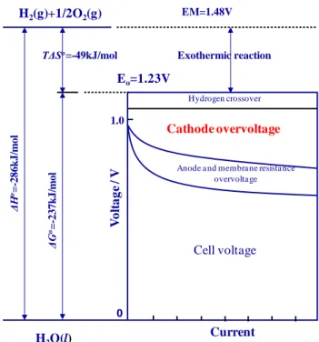
Figure 2.2 Current-Voltage characteristics and thermodynamic properties of actual PEMFC
2.2 The oxygen reduction reaction (ORR)
The cathode reaction in the current Polymer Electrolyte Fuel Cell (PEMFC) is the oxygen reduction reaction (ORR) at the catalyst (ex. platinum) surface in an acidic electrolyte. The ORR is a highly irreversible reaction even at temperatures above 100°C and at the best existing electrocatalysts - platinum [8, 9]. The overall four-electron reduction process of O2 in acid aqueous solutions is
O2 e 2 2O
Eq. 2.19 and the equilibrium potential is
N E
V
Eq. 2.20 Since the four-electron reduction of the oxygen is highly irreversible, experimental verification of the thermodynamic reversible potential of this reaction is very difficult. The exchange current
Fig. Current-voltage characteristics of actual PEFC.
V o lt a g e / V 0 Hydrogen crossover Cathode overvoltage
Anode a nd membra ne resista nce overvolta ge 1.0 Eo=1.23V Exothermic reaction TΔSo=-49kJ/mol ΔH o= -286 k J/ m ol ΔG o= -237 k J/ m ol H2(g)+1/2O2(g) H2O(l) Cell voltage EM=1.48V Current
density for the reaction is typically in the range of 10-8–10-10A cm-2of real surface area for Pt at room temperatures. Any other side reaction, even if slow and difficult to detect, may compete with reaction Eq. 2.19 and affect the remaining potential. Indeed, unless special experimental procedures are used, the thermodynamic potential cannot be obtained at ambient temperature in aqueous electrolytes from experimental measurements. Even if the most active platinum electrodes are used in pure acid or alkaline aqueous solution under ordinary conditions, the remaining potential in the presence of oxygen at 1 atm and ambient temperature usually does not exceed 1.1 V vs. the Reversible Hydrogen Electrode (RHE) and most often has a value close to 1.0 V. These values are different from the theoretical value of 1.23 V. On the other hand, evidence showed that platinum dissolves in both acid and alkaline electrolyte at potentials of less than 1.0 V vs. RHE [10, 11]. Thus the anodic dissolution of Pt may be the steady-state complementary reaction. The dissolution may proceed through the direct dissolution of the platinum or through a Pt-OH or Pt-O intermediate. A review of the problem is offered by Norskov et al. [12]. The general methodology used to analyze the kinetics of the reaction is introduced here. In order to analyze the kinetics, we may use the general current-overpotential equation. For a one-step reaction taking place on a planar electrode surface, the governing equation is [13],
Eq. 2.21 where CO and CR are the concentration of oxidant and reductant on the electrode surface; the
superscript * indicates in bulk phase; α and β are the transfer coefficient of the anodic and cathodic reaction respectively. η in the equation is the overpotential, defined by , and
Eq. 2.22 where E0 is the formal standard equilibrium potential, namely, the potential when concentrations of the reactant and product are the same. i0 in Equation Eq. 2.21 is the exchange current density, i.e., the anodic or cathodic current of the reaction at equilibrium condition, when E=Eeq.
When Equation Eq. 2.21 is combined with the Rotating Disk Electrode (RDE) measurement, some kinetic parameters of the oxygen reduction reaction can be obtained. So far, it is widely accepted that in aqueous acid electrolyte, the reaction on the Pt electrode is a four-electron kinetic process, with the first charge transfer as the rate determining step [9]. A description of a detailed model for the reaction mechanism will be reviewed in the following section.
2.2.1 Electrode kinetics of the oxygen reduction reaction
The ORR is a multi-step reaction that usually can be divided into several elementary steps in the reaction mechanisms. In aqueous solutions, the ORR occurs mainly through two overall pathways: a “direct” four-electron reduction and a “peroxide” pathway, which involves 2O2 as the intermediate [14]. The direct four-electron pathway in an acid solution is as shown in Eq. 2.19.
The peroxide pathway is
O2 2 2e 2O2 0. V
Eq. 2.23 Peroxide can undergo further reduction or decomposition in acid solutions, via the reactions:
2O2 2e 2 2O O2 E 1. V
2O2 2 2O O2
Eq. 2.24 The rotating ring-disk electrode technique was the principal tool used to quantitatively determine the extent of these reactions. The oxygen reduction took place on the disk while the H2O2 was monitored by the ring which was maintained at a potential sufficiently positive to oxidize the peroxide back to O2 at the diffusion limiting current.
Damjanobic et al. [15, 16] proposed the first O2 reduction reaction schematics analyzed by the disk-ring current data at various rotation speeds. Later, based on the rotating disk-ring data for O2 reduction on various electrode materials, Bagotskii et al. [17] proposed a more general schematics for the series-parallel reactions of O2 and H2O2 as shown in Figure 2.3. In this reaction scheme, O2, (O2)*, and (O2)a represent molecular O2 in the bulk solution, in the solution adjacent
to the electrode surface, and in the adsorbate state, respectively. The O2 can be reduced either directly to water with the rate constant (k1) without formation of intermediate H2O2 or through a series pathway (k2, k3) to water with the formation of intermediate H2O2. This intermediate can also desorb from the electrode surface into the bulk solution resulting in a two-electron reduction of O2 (k6) or be electrochemically oxidized back to O2 (k2’). On the other hand, heterogeneous decomposition of H2O2 can occur non-electrochemically through a disproportionate reaction involving a direct electron transfer between two (H2O2)a species and not through the electrode phase. The analysis by Bagotskii shows that the number of the rate constants involved in the reaction scheme is greater than the number of independent equations. Therefore, it is impossible to determine all the above-mentioned constants from the rotating disk-ring electrode data for the O2 reduction alone.
Figure 2.3 Bagotskii et al.’s schematic for the oxygen reduction.
Wroblowa et al. [18] have used a simpler scheme in which an adsorbed (O2)a state is not considered explicitly but the desorption process of H2O2 is still included inside. Wroblowa et al.'s scheme has the same number of rate constants and independent equations, and it is most often used to analyze experimental ring-disk data. However, oversimplified schemes cannot provide enough information to determine the reaction pathway. For instance, Damjanovic et al. omit the (H2O2)* state and do not consider slow desorption of H2O2 which leads to insufficient diagnostic criteria regarding the series and direct paths for the O2 reduction.
Anastasijebic [19] proposed a more comprehensive scheme that includes almost all the possible intermediates, based on the previous schemes discussed in the literature. Although, as in other previous schematics, there are more variables to be determined than the number of available equations, after carefully analyzing those equations, the authors provided some clear criteria to
determine some of the kinetic parameters of ORR. These criteria clarify some issues which were not determined well before. The general schematic is as shown in Figure 2.4.
Figure 2.4 Bagotskii et al.’s schematic for the oxygen reduction.
The original schematic has been written for alkaline solution, but it is transformed into an analogous schematic here for acid solution, in order to maintain consistency with previous schematics discussed above. The ki are overall rate constants for the i* step; the parameters with the subscripts a, sa, and * denote adsorbed, strongly adsorbed, and in the solution adjacent to the electrode surface, respectively; without a subscript denotes in bulk solution.
This schematic is the most comprehensive schematic proposed so far and, as before, consists of two major paths by which ORR can take place, i.e., the O2 can be electrochemically reduced either directly to water without formation of the intermediate hydrogen peroxide or with the intermediate hydrogen peroxide. The adsorbed hydrogen peroxide can be either reduced to water, oxidized back to O2, decomposed on the electrode surface into O2 and H2O, or desorbed and diffuse into the bulk of the solution. Two main features of this schematic make it distinct from previous ones indicated in reference [19]and shown in Figure 2.5: (1) the superoxide species (HO2) can explicitly be an intermediate; and (2) weakly adsorbed intermediates from the series path can undergo surface diffusion and form their strongly bound counterparts in the direct path. The disk current ID for this schematic is given by
Eq. 2.25 while the ring current is given by
Eq. 2.26 where A is the area of the disk, N is the collection efficiency, is the rotation speed, nR is the
number of electrons exchanged on the ring electrode, and Z is a diffusion parameter for H2O2 (Z=0.62D2/3/ν), with diffusion coefficient D and solution kinetic viscosity v . The Subscripts 1, 2, 3, 4, and 5 have been used for the O2 molecule, the hydrogen superoxide, hydrogen peroxide, the oxygen atom, hydroxyl, respectively. Although it is impossible to obtain all of the rate constants in the reaction schematic, one can draw some qualitative conclusions and obtain some information as to the pathway of the reaction by the careful examination of experimental data. The equation relating the ratio of currents at the disk (ID) and ring (IR) to the electrode rotation
rate are as follows:
Eq. 2.27 where A0 and A1 are dimensionless function of the rate constant. The intercepts
and slopes from the vs. plots are related by the equation
Eq. 2.28 where J and S are the ordinate intercepts and slopes at various potentials, and A3 is a
dimensionless function of rate constants. Anastasijevic et al. drew some conclusions after careful examinations of these equations Equation Eq. 2.25-Eq. 2.28: (1) Linearity of the vs.
plot is sufficient proof for a first-order reaction; (2) when the equilibrium of
adsorption/desorption of H2O2 does not exist, S=0; (3) a non-linearity of J-S plot occurs when an interactive pathway is involved, in which diffusion of species from series path into a direct path takes place. (4) linearity of J-S plot with the J-axes intercept is a characteristic of a true parallel pathway. In such a case, the ratio of the direct pathway to the series pathway can be evaluated. These criteria provided a way to obtain the most extended information on ORR that the rotating disk ring technique can provide. Further insight into the mechanism of the ORR will depend largely on the spectroscopic methods with the ability to detect intermediates associated with the reaction.
Due to considerable non-uniformity in the terminology for the reaction schematics of the O2 reduction, Adzid proposed a clearer standard to classify the ORR pathways. It is defined as:
1) a direct four-electron reduction to H2O (in acid) or to OH- (in alkaline medium) without hydrogen peroxide detected on the ring;
2) a two-electron pathway involving reduction to hydrogen peroxide;
3) a series of pathways with two- and four-electron reduction. The case of only four-electron reduction without hydrogen peroxide detected on the ring is indistinguishable from a direct four-electron reduction;
4) a parallel pathway that is a combination of 1), 2), and 3); and
2.2.2 Electrode kinetics of ORR at platinum surface
It is widely accepted that oxygen electroreduction on platinum occurs through parallel reaction pathways with predominately direct four-electron reduction [8, 9]. However, the details of the mechanism remain elusive. The overall ORR is a multi-step process involving four-electron transfers during which bonds are broken and formed. It is still not clear whether the process starts from the oxygen molecule dissociation on the Pt electrode, which is followed by electron and proton transfer, or whether the first reduction step happens before O-O bond cleavage. To answer this question, the information about the site and the configuration of O2 adsorbed on a Pt electrode surface is critical. Three plausible types of O2 adsorption were proposed by earlier researchers, viz., Griffith (on-top, double bond) [20], Pauling (on-top, single bond) [21], and bridge[22] as shown in Figure 2.6.
Figure 2.6 Models of O2 adsorption on electrode surfaces.
These types of bonding are well-known in inorganic coordination chemistry. They are also expected to occur for platinum-group metals. According to these models, O2 interacts with electrode surfaces in the following ways:
O2 interacts with a single substrate atom (Griffith model) by forming a bond mainly between its σ orbitals and the empty dz2 orbitals of the metal surface atom, and by forming a σ back-bond
from the partially filled dxy or dyz metal orbitals to the antibonding π* orbitals of O2 [23].
End-on adsorption through a single type bond (Pauling model), in which the σ orbital of O2 donates electron density to an acceptor dz2 orbital on the metal.
Bridge model, with two bonds with two sites, which was proposed by Yeager principally for the reaction on platinum-group metals.
Oxygen adsorption on clean metal surfaces at the metal-gas interface has been the subject of numerous studies in order to establish the nature of the chemisorption, the bond strength, and the structure of the absorbed layer. Oxygen adsorbs in molecular form at low temperatures, while dissociative adsorption on platinum-group metals occurs. From the experimental point of view, there is evidence of dissociative adsorption of O2 on platinum at temperatures in the range of 150-300K [24, 25], but there is no evidence for the direct cleavage of O-O bond at the electrochemical interface.
Now, it is well established that the reaction rates of oxygen reduction on different low-index Pt surfaces are structure-sensitive, due to structure-sensitive adsorption of intermediates (O2,ads and OOHads) and species (OHads). From these reasons, the adsorption of OH is probably the most important in the process. In 0.05 M H2SO4, the ORR rate increases in the sequence Pt(111) < Pt(100) < Pt(110) [26]. An exceptionally large deactivation is observed on Pt(111) surface due to the blocking and electronic effect of strongly adsorbing (bi)sulfate anion.
In perchloric acid solution, the variation of activity at 0.8-0.9 V is relatively small between the three low-index surfaces, with the activity increasing in the order Pt(100) < Pt(110) ≈ Pt(111) [27]. A similar structural sensitivity is observed in 0.1 M KOH. In the potential range where oxygen reduction is under combined kinetic-diffusion control (E > 0.75 V), the activity increases in the sequence of Pt(100) < Pt(110) < Pt(111) [28]. The decrease of Pt(100) surface activity is related to the high affinity of (100) sites for the hydroxyl adsorption, leading to a lack of active centers for O2 adsorption because the Pt(100) surface is highly covered by OHads. Markovic et al. suggested O2 reduction should be proportional to the part of the surface not covered by hydroxyl species (1-ΘOH) [29].
Figure 2.7 Relationship between logarithm of current density (i) [30] and overvoltage (η) [31] for ORR on various noble metal cathodes. The current density was obtained at 0.8 V vs. RHE in 85%
H3PO4 (25°C). The overvoltage was obtained at i=10-5 A cm-2 in 0.5 M H2SO4 (25°C).
2.3 Catalysts materials for the ORR
2.3.1 Platinum and platinum-alloys materials
Platinum has been the best catalyst for over 170 years since Christian Friedrich Schoenbein and William Robert Grove reported the first study on fuel cells [2]. However, this does not mean that platinum is the optimal material for fuel cell application, because of its fundamental catalytic property limitations, very high cost, limited reserves, and political issues. Therefore a future commercialization of PEMFCs cannot be based solely on platinum-based technologies. It is essential to develop a catalyst having higher ORR catalytic activity and high cost-performance for the future.
Figure 2.7 summarizes the works of D.S. Gnanamuthu and A.J. Appleby, the relationship between the logarithm of current density (i) [30, 32] and overvoltage (η) [31] for ORR on various noble metal cathodes. The current density was obtained at 0.8 V vs. RHE in 85% H3PO4 (25°C). The overvoltage was obtained at i=10-5 A cm-2 in 0.5 M H2SO4 (25°C). The figure indicates that palladium has the second highest catalytic activity in the acid media after platinum. Palladium potentially has a high catalytic activity for ORR in acid media, as we can see in these studies.
Toda et al. have conducted studies on thin layers of sputter-deposited PtNi, PtFe, and PtCo, and reported extremely high-activity enhancement factors of 10–20 [33]. However their baseline of Pt activity is 10 times lower than what other researchers reported in their literatures. It is likely that there is significant doubt on the validity of their measurements. Paulus et al. have reported kinetic studies on high-surface-area Pt-based alloy catalysts such as Pt/Vulcan, PtNi/Vulcan, Pt3Ni/Vulcan, PtCo/Vulcan, Pt3Co/Vulcan, and PtRh3Fe7/C [34, 35]. The catalytic activity gains for ORR were compared to the activity of bulk Pt. Specific activity enhancements of a factor of 2-4 compared to bulk Pt were found in these studies. In addition to this work, E.R. Gonzalez et
al. have reported catalytic activity enhancements by alloying with -Co, -Ni, and Fe. These studies
support that alloying with 3d-transition metal such as Co, Ni, and Fe enhances the electrocatalytic activity for ORR of platinum electrode.
The fact that palladium potentially has a high catalytic activity for ORR and that alloying with the 3d-transition metal enhances the catalytic activity of the base element suggests that alloying can also enhance the electrocatalytic activity of palladium electrode. Palladium-Cobalt binary alloy was selected in this study, since Pd-Co exhibited the best ORR catalytic activity between Co, Cr, Ni in our previous study [3]. Pd-based alloy with other 3d-transition metals will be studied as my future works.
2.3.2 Palladium and palladium-alloy materials
The first Pd-based alloy catalysts for PEMFC application were presented by O. Savadogo et al. in 2004 [3]. Pd-Co alloy (72:28) and Pd-Cr alloy (70:30) prepared by sputtering method has shown enhanced electrocatalytic activities to Pd electrode. Following up on this work, the second paper
by O. Savadogo et al. presented the performance of Pd-Co alloy (78:22 and 72:28), Pd-Ni (64:36), and Pd-Cr (61:39) [36].
V. Raghuveer et al. prepared carbon-black-supported Pd-Co-Mo (70:20:10) catalysts by use of a conventional borohydride reduction method in 2005 [37] and carbon-supported Pd-Co-Au catalysts by use of the conventional reduction method and a reverse microemulsion method in 2006 [38]. The former showed a particle size of 15-35 nm, and the latter a size of 15-46 nm. The mean particle sizes increase by increasing the heat treatment temperature for both cases.
The work of M.H. Shao et al. in 2006 synthesized Pd monolayer catalysts on different single-crystal substrates; Ru(0001), Rh(111), Ir(111), Pt(111), and Au(111) [39]. The electrocatalytic activities increase in the order of Pd/Ru(0001) < Pd/Ir(111) < Pd/Rh(111) < Pd/Au(111) < Pd/Pt(111). They also prepared Pd-Co (2:1) carbon-supported catalysts having broad size distribution up to 92 nm, peaking at 18-20 nm.
L. Zhang et al. prepared carbon-supported Pd-Co alloy nano-particle catalysts (67:33) [40] by using the co-impregnation method with NaBH4 as reducing agent, and obtained fine particles in the range of 4.8-14 nm. The catalyst with a mean particle size of 4.8 nm is relatively small – for example, the size of a commercial carbon-supported Pt catalyst widely used for fuel cell applications is in the range of 2 to 4 nm – however the particles are not well dispersed on carbon supports (as seen TEM image). More particles would be located more closely in the case of a nano-scale carbon-supported catalyst with a metal loading of 20 wt %.
One of the most interesting parts of this study was presented by K. Lee et al. in 2006 [41]. Pd-Co (60:40), Pd-Ni (64:36), and Pd-Cr (61:39) prepared by the sputtering method were developed for the Direct Methanol Fuel Cell (DMFC) cathode, and have the function of ORR selectivity in the presence of methanol. DMFCs have two very serious technical problems, i.e., low catalytic activity of the anode electrocatalyst and methanol crossover in which the methanol permeates from the anode compartment through the electrolyte membrane to the cathode compartment [42, 43]. The latter is concomitant with cathode performance losses due to the formation of mixed potentials on the cathode electrocatalysts as well as the decrease in the efficiency of methanol utilization. Approximately one-third of the available energy is lost at the cathode and the other one-third is lost at the anode [44]. It has been found that these kinds of Pd-based alloy catalysts
have high potential to be used as a DMFC cathode because of their very low activities for methanol oxidation.
X. Wang et al. managed to obtain fine Pd-Co particles on carbon support having a mean particle size in the range of 1.8 to 11.2 nm by use of a modified polyol reduction method [45]. The catalyst of Pd2Co/C heat-treated at 500°C successfully obtained relatively smaller particles, however, the particles are non-uniformly distributed, and the presence of particles larger than 10 nm seems to be higher than the given histogram. Since 300 particles have been randomly counted for the histogram, more smaller particles may be found in another TEM images, but the TEM images of all other catalysts, especially the one for the smallest particle size of 1.8 nm, are needed to support the fact that this modified polyol reduction route makes it possible to obtain nano-scale alloy catalysts with a narrow particle size distribution and a good dispersion on a support, as the authors mentioned in the report. Yet the modified polyol method is interesting for nano-scale Pd-Co catalyst preparation, and this method was examined by H. Liu and Manthiram in 2008 [46].
L. Zhang et al. investigated the effects of reducing agents in the co-impregnation method following up on their previous work [47]. The method with ethylene glycol (EG) has provided the smallest mean particle sizes in the range between 4.6 and 6.6 nm, even though the catalysts were heat-treated at 700°C. The one with NaBH4 yielded a mean particle size in the range of 4.6 to 13.3 nm, and the last one with HCHO was in the range of 8.8 to 22.9 nm. The catalysts prepared by EG and NaBH4 with no heat treatment show well-distributed fine particles. In contrast, many aggregated particles can be seen for the one by HCHO.
J. Mathiyarasu and K.L.N. Phani studied carbon-supported Pd-Co-based ternary alloy (Au, Ag, Pt) nano-catalysts prepared by use of a reverse microemulsion method for methanol-tolerant oxygen reduction cathode materials having a mean catalyst particle size in the range of 18 to 29 nm [48]. Pd-Co-Pt ternary alloy catalyst shows the best ORR catalytic activity among them, and all of these Pd-based ternary alloys including Pd-Co binary alloy perform very low-oxidation activities for methanol.
The work on thin-layer catalysts of Pd-Co binary alloy prepared by use of electrodeposition has been reported by Tominaka et al. in 2008 [49] and is consistent with the work of K. Lee – the Pd-Co alloy possesses high methanol tolerance.