OATAO is an open access repository that collects the work of Toulouse researchers and makes it freely available over the web where possible
Any correspondence concerning this service should be sent
to the repository administrator: [email protected] This is an author’s version published in: http://oatao.univ-toulouse.fr/24281
To cite this version:
Susainathan, John and Eyma, Florent and De Luycker, Emmanuel and Cantarel, Arthur and Bouvet, Christophe and Castanie, Bruno Experimental investigation of compression and compression after impact of wood-based sandwich structures. (2019) Composite Structures, 220. 236-249. ISSN 0263-8223
Official URL:
https://doi.org/10.1016/j.compstruct.2019.03.095 Open Archive Toulouse Archive Ouverte
Accepted Manuscript
Experimental investigation of compression and compression after impact of wood-based sandwich structures
John Susainathan, Florent Eyma, Emmanuel De Luycker, Arthur Cantarel, Christophe Bouvet, Bruno Castanie
PII: S0263-8223(18)34110-2
DOI: https://doi.org/10.1016/j.compstruct.2019.03.095 Reference: COST 10823
To appear in: Composite Structures
Received Date: 12 November 2018 Accepted Date: 26 March 2019
Please cite this article as: Susainathan, J., Eyma, F., De Luycker, E., Cantarel, A., Bouvet, C., Castanie, B., Experimental investigation of compression and compression after impact of wood-based sandwich structures,
Composite Structures (2019), doi: https://doi.org/10.1016/j.compstruct.2019.03.095
This is a PDF file of an unedited manuscript that has been accepted for publication. As a service to our customers we are providing this early version of the manuscript. The manuscript will undergo copyediting, typesetting, and review of the resulting proof before it is published in its final form. Please note that during the production process errors may be discovered which could affect the content, and all legal disclaimers that apply to the journal pertain.
Experimental investigation of compression and compression after
impact of wood-based sandwich structures.
John SUSAINATHAN1, Florent EYMA1, Emmanuel DE LUYCKER2, Arthur
CANTAREL1, Christophe BOUVET1, Bruno CASTANIE1
1 Institut Clément Ader (ICA), Université de Toulouse, CNRS UMR 5312-INSA-ISAE-Mines Albi-UPS, Toulouse, France.
2
Laboratoire Génie de Production (LGP), Université de Toulouse, EA 1905 INP-ENIT, Tarbes, France.
Abstract
This paper presents an experimental investigation of compression on pristine specimens and the compression after impact (CAI) response of wood-based sandwich structures. Nine different types of sandwiches, made with plywood core and different aluminum or composite (carbon or glass or flax fiber) skins, are studied. Impact energy levels were fixed at 5 J, 10 J and 15 J in order to create significant defects. Failure modes and damage scenarios are analyzed. The influence of different skins with plywood core is explained in terms of residual strength, residual stiffness, and specific properties. It is shown that this type of structure exhibits very interesting compression properties in terms of specific strength, which is superior to a reference sandwich used for aircraft flooring, and in terms of behavior, with large plateau areas that can be useful for crash issues.
Keywords: Wood Impact Sandwich Damage,
Compression After Impact
1. Introduction
Low impact resistance is the main issue of laminate or sandwich structures in the structural design of components in aeronautics or, more generally, in the transportation sector. A tremendous decrease in the residual strength of laminated or sandwich structure under compression loading may occur when it is subjected to low-velocity / low-energy impacts. This kind of impact may occur when a tool is dropped on the assembly line or during maintenance, causing minor apparent damage. It leads to the concept of damage tolerance, which was mainly developed in the early 1980s by Airbus engineers for the certification of the ATR 72 outer wing box [1], the first carbon primary structure ever certified in the field of civil aviation. In order to check the residual strength, a CAI (Compression After Impact) test was designed to ensure the most conservative design and find allowables in the form of maximum strains [2]. Numerous studies concerning impact and compression after impact on sandwich structures are available in the literature [3]. Studies of CAI focus on modeling the residual strength with analytical [4, 5] or semi-empirical approaches [6] or, more usually, with a finite element strategy [7-12]. The physical mechanisms behind the failure modes that lead to the final rupture have been clearly explained in [13] and [14]. The response is a combination of three nonlinearities: a nonlinear geometric behavior due to the shift of the neutral plane because of the residual dent, material nonlinear behavior of the core, and plastic
or damage behavior for metallic or composite skins, respectively. Once this behavior was understood, an original core crush criterion was proposed to compute the residual strength [14]. Other studies focus on the influence of material properties, such as fiber and resin type (thermoset or thermoplastic) [15-17], transverse reinforcement like stitching [18,19] or Z-pinning [20], fabric as an alternative to unidirectional tape [21, 22] and aging [23,24], on the evolution of residual strength. The influence of a protective layer [25] or preloads [26] has also been studied.
All the papers cited above are restricted to laminates or classical sandwich structures with foam or honeycomb cores and composite skins. Only sandwiches with balsa core have been widely studied, because of their practical application in marine structures (for example [27-28]). In a very interesting study, the beneficial effect of wood used as a shield against hypervelocity impacts was also demonstrated by Wen et al. [29]. Sandwiches with classical foam cores but with intermediate layers made of ash wood or rubber cork have been analyzed under low-velocity impact and the benefit of the additional layers was demonstrated by Demircioğlu et al. [30]. The same authors also studied the compression after impact response of this kind of sandwich [31] and this is the only reference found on this subject to date.
The authors of this paper have recently studied the manufacturing and the static behavior of sandwiches made with plywood core and different skins made of aluminum, glass, carbon and flax fiber laminates [32], and their low velocity, low energy impact response [33]. A first attempt to model the impact damage has been proposed [34] and the present paper focuses on compression and compression after impact (CAI) tests performed on the nine types of wood-based sandwich structures studied in [32-34]. Materials used in this study will be recalled briefly in the form of some impact results.
2. Materials and methods 2.1. Sandwich manufacturing
In comparison with simple wood, plywood structures have much better physical properties, due to the material’s better in-plane behavior. In order to develop a new structure and to compare configurations, we used two different plywood cores with four different skins [32-35]: two different configurations of plywood, named “A” and “B” and composed of different plies obtained from poplar and okoume wood that were bonded together using Melamine Urea Formaldehyde (MUF) resin. The stacking sequences of okoume and poplar plies are given in Table. 1.
Plywoods A and B had the same thickness and were used as the core with different skins or face sheet materials made of aluminum, or fiber-reinforced polymer composite such as carbon, glass, or flax. A constant core thickness was chosen to prevent any effect of geometry on the bending stiffness. Samples were manufactured by thermo-press or vacuum molding using prepreg (Table 2) in order to evaluate the influence of the manufacturing process [32]. The skin materials were chosen to be representative of the different types of face sheets used in sandwich construction. For all the plywood with aluminum or composite skin containing flax, glass and carbon, the skins were bonded on each side of the core material using an epoxy resin. For plywood A, with glass or carbon skin, they were fabricated by vacuum bag molding using carbon or glass composite prepreg. In the case of plywood B, with various skins such as flax, glass and carbon skin, the sandwiches were manufactured by thermo-compression using composite prepreg. The thermo-press process led to better adhesion between skin and core due to its high working pressure [35]. The size of the specimen was 100 x 150 mm² after trimming according to Airbus (AITM 1-010) or Boeing standards for low energy impact tests and compression after impact tests.
2.2. Experimental investigation 2.1.1. Impact
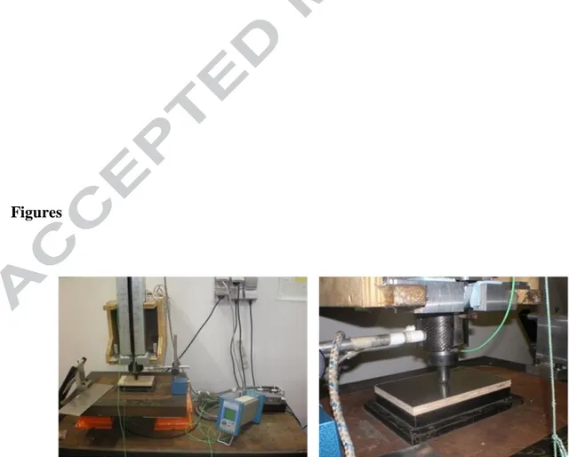
Impact tests were performed using a drop weight apparatus (Fig. 1) followed by tomographic analysis [33, 35]. Low velocity impact tests were carried out at three energy levels (5 J, 10 J and 15 J), corresponding to energy levels generally encountered in industry, to simulate tools falling onto a floor. The principle of the falling weight is to drop an instrumented mass and guide it in a tube onto a sample plate held by a support window.
2.1.2. Compression after impact
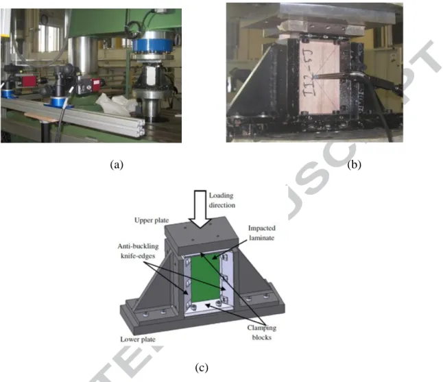
The purpose of these tests was to determine the loss of compression strength of an impacted specimen compared with a pristine specimen. The CAI tests were carried out at room temperature using an MTS machine as shown in Fig. 2 with a loading cell of 150 kN. This assembly was developed in order to meet the AIRBUS standard AITM 1-0010 and was the same as in references [13, 17, 25, 35]. The use of clamping knives on each side of the test piece enabled "all-supported" boundary conditions to be applied and thus prevented an overall buckling process before the impact damage propagated. The pristine and impacted specimens of wood-based sandwich structures were compressed along the length direction at a constant displacement rate of 1.2 mm/min. The impacted face was painted white and sprayed with black dots so that the evolution of the depth and shape of the dent could be observed by 3D digital image stereo correlation (D.I.C.). Two CCD cameras were placed in front of the impacted face of the specimen (see Fig. 2a) to capture changes in the in-plane and out-of-plane displacement of the impacted face.
The rear side of specimens (corresponding to the bottom face of the impacted sample) was instrumented with an LVDT sensor to measure the evolution of deformations during the experiment (see Figure 2b). The CAI test rig is recalled Figure 2c. The compression force was (a)
measured directly by the load cell. The test matrix for the 36 tests performed is shown Table 3. The reference specimen called HC aramid was a floor actually used in aircraft. It had carbon skins and a 10 mm thick Nomex honeycomb core [33].
3. Results and discussion
3.1. Impact behavior.
In this subsection, some key points of the impact behavior of these sandwich structures are recalled. Details are presented in [33]. The force-displacement curves for all the specimens tested for impacts at 15 J are recalled in Fig. 3. The initial stiffenesses differed for the 8 configurations tested, due to the different materials of the skins. Concerning plywood structures, plywood A was found to yield slightly better results than plywood B in terms of absorbed energy and indentation, as it had a longer plateau. In terms of specific energy absorption, the sandwich floor gave the highest results, thanks to its low density, but the low density of the plywood also enabled it to give good results regarding specific energy absorption [33].
For plywood structures with aluminum skins, the response was comparable to those of classical sandwiches with foam or honeycomb cores: there was no plateau and peak force oscillation occurred due to the high strength and stiffness of the skins. This structure showed comparable energy absorption and better resistance to indentation than the reference material but was not as good in terms of specific energy absorption, because of the high density of the aluminum skin. Moreover, this structure resulted in a deeper indentation than any of the other structures with composite skin and this can be undesirable in some applications.
The sandwiches with CFRP skins showed weak results. There was a small dent due to the elastic behavior of the skins, with a large delamination area in the skin and severe crushing of the plywood core. With glass fiber reinforced composite skins, the perfect adhesion and the spring back effect of the skin limited delamination, resulting in an absorbed energy
comparable to that observed with flax fibers. Whatever the impact energy, this material proved to be the best compromise between absorbed energy and indentation. When flax fiber reinforcement was used in the skins, the composite behaved similarly to plywood with aluminum skins in terms of absorbed energy and specific energy absorption but showed smaller indentation as the plastic deformation was lower than for aluminum. There was minimum delamination and debonding between skin and core because of the moderate elastic spring back effect. All these results are presented in more detail in [33].
4.2. Compression After Impact
To analyze the experimental results, the structural strength (or failure) was calculated from the load at which a change of slope (typically more than 5%) occurred in the load– displacement plot as illustrated in Fig. 4. In practice, this value is important for design and was introduced in [36]. Residual strength corresponded to the maximum compressive load reached.
4.2.1. Plywoods A and B.
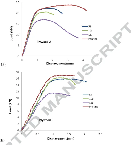
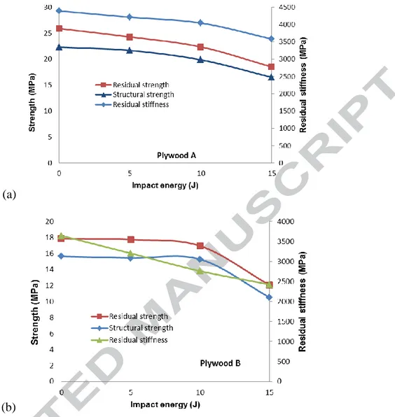
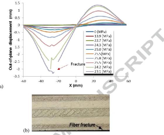
The load/displacement curves obtained for plywoods A and B are shown Fig. 5 (a) and (b). The evolution of residual strength, structural failure and residual stiffness are given Fig. 6. In general, plywood (A) had better mechanical properties than plywood (B). The degradation of the mechanical characteristics was more progressive and the residual strength reductions were 28% and 32.6% respectively. It can also be noted that, in the pristine state, plywood A had a very long plateau (Fig. 5 (a)) of practically 3 mm. This mechanical characteristic could be of interest in a crash. For plywood B in new condition, the length of the plateau was only 0.5 mm because the test was stopped prematurely. The compression failure scenarios of the two new plywoods were quite different. Plywood A gradually deformed out of plane following a mode II (in the sense of Euler beam theory), see Fig 7 (a)
and the upper fold of okoume at 0° ended up breaking in traction at the tip of wrinkle (Fig. 7 (b)).
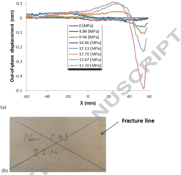
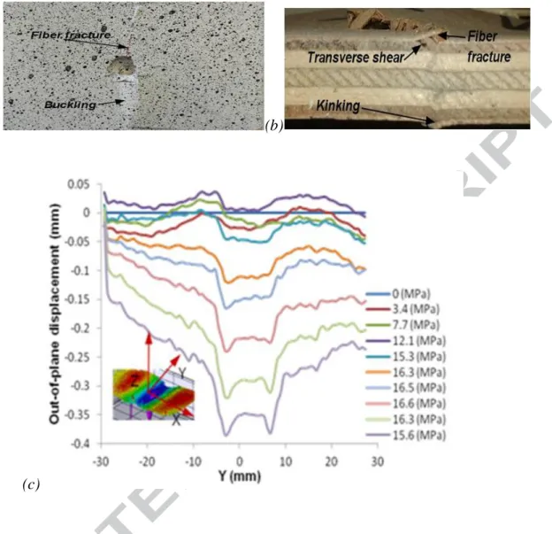
For pristine plywood B, it would appear that the same mode of out-of-plane displacement was activated at the beginning of the loading but, towards 17.13 MPa, a weakness (local buckling?) appeared at the end of the specimen near the zone of loading (see Fig 8 (a)) and changed the deformed shape. The post-mortem analysis showed a rupture of the outer, okoume ply at 0°, see Fig 8 (b). Since the plywood had not been locally reinforced, it is possible that the rupture was premature. Unwanted local buckling in this zone is common in conventional sandwiches [13] and the outer okoume ply was superimposed on 2 poplar plies oriented at 90°, and therefore not rigid (Table 1), which may have caused local buckling. The post-impact behavior of the two plywoods is shown in Figure 9. Typical post-impact fracture patterns are visible in Figure 9 (a) and (b), as well as the evolution of out-of-plane displacement measured by DIC in an off-impact zone for plywood B at 5 J impact. For the 6 different configurations, the failure was generally brutal in compression, as shown in Fig. 9 (b). In this case, we have a rupture scenario close to that for laminates [8-12]. Sometimes it can be preceded by an increase in depth of the impact dent, as shown in Fig. 9b, and even a local buckling of the upper ply. In this case, the scenario is closer to sandwich behavior [13,14].
4.2.2. Reference sandwich
The overall load/displacement results and the strength reduction vs impact energy for this sandwich are shown in Figure 10. The strength reduction reaches 70 %, which is very great but also almost classical [37]. In this sandwich, the core is made of Nomex honeycomb, which is weak with respect to out-of-plane loads, and the skins are very thin (about 0.5 mm), two features that can explain these results. The failure scenario for this sandwich is classical [14, 37] and will not be recalled here.
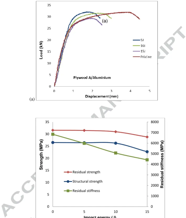
4.2.3. Plywood structures with aluminum skin
The overall load/displacement results and the strength reduction vs impact energy are shown in Figure 11. The sandwich with aluminum skins exhibits interesting results. For the pristine specimen, a very long plateau area is found. This behavior should be useful in crash situations. Moreover, even with impact, the loss of strength is less than 1% for 5 and 10 J impacts and reaches 15 % for the 15 J impact. This behavior may be due partially to the very ductile behavior of 1000 series aluminum. The pristine specimen fails by local skin buckling, located at the center of the specimen (see Fig. 12 (a)). For the impacted specimens, two phenomena seem to compete: on the one hand, the increase in depth and extension perpendicular to the compression direction of the residual indentation in the center of the plate, a phenomenon already described in [13, 14, 37] and, on the other hand, an appearance giving the impression of local buckling at several places on the aluminum skin (see Fig 12 (b)), on 3 of the 4 sides of the dent. It has been observed that, during impact, a delamination occurs at the edge of the dent [33], which may explain these occurrences. Lateral buckling, perpendicular to the compression direction, ultimately produces skin failure. This scenario is corroborated by the DIC measurements (Fig. 13) for an impact of 15 J. In Figure 13 (a), an increase in depth and an extension of the dent can be observed in a qualitative way as can the 3 points of local buckling around it. Figure 13 (b) shows the evolution of the displacements in the median plane of the specimen.
4.2.4. Plywood structures with composite skins.
a. Carbon composite skins
The overall load/displacement results and the strength reduction vs impact energy are shown in Figures 14 and 15, respectively, for the two types of sandwich, i.e. plywood A + carbon skins Vacuum Molded (VM) and plywood A + carbon skins obtained by Thermo-Compression (TC). The behavior is almost the same for pristine specimens and for
impacted specimens, with nearly linear behavior followed by a sudden drop. The plywood A specimen impacted at15 J has different behavior with a large plateau area - probably because of the large extent of the damage. The residual strength falls by 30 % for plywood B/ carbon skins TC and by 35 % for plywood A/ carbon skins VM. It is noticeable that this drop remains limited in comparison to the reference sandwich (up to 70%) and may be interesting in terms of sizing, despite the heavier weight. Also, the sensitivity to the manufacturing process highlighted in [32] is not found here.
After the impact, the carbon skin is delaminated due to its high stiffness and has strong spring-back, so the permanent indentation is slight. Nevertheless, the wood is still crushed below the skin and the skin becomes unsupported [33]. This failure pattern is very similar to that in impacts on sandwich structures with Nomex honeycomb cores and carbon skins, where the honeycomb is crushed under the residual dent [38, 39]. So the behavior is almost the same as described in [13, 14] and explains the shape of the curves in Figure 14 and the local skin buckling visible in Figure 16 . The only significant difference is the shape of the buckling found for the 15 J impact of plywood A with carbon skin (see Fig. 17) where the load/displacement curve has a plateau. The buckling is so large that a second mode appears (in an Euler beam sense), which is probably due to a large crushing area combined with debonding (due to a poor manufacturing process) between carbon skin and plywood after the impact.
b. Glass composite skins
The overall load/displacement results and the strength reduction vs impact energy are shown in Figures 18 and 19 respectively. Unlike the other configurations, this one experiences a rapid drop in strength, even for the 5 J impact, which also reaches 35 %. The loss in stiffness and in structural failure is nearly inexistent. The failure scenario is a local bucking of
the unsupported skin near the impact (in a direction away from the plywood) followed by a brittle failure at the tip of the wrinkle (see Fig. 20 for the 15 J impact).
c. Flax composite skins
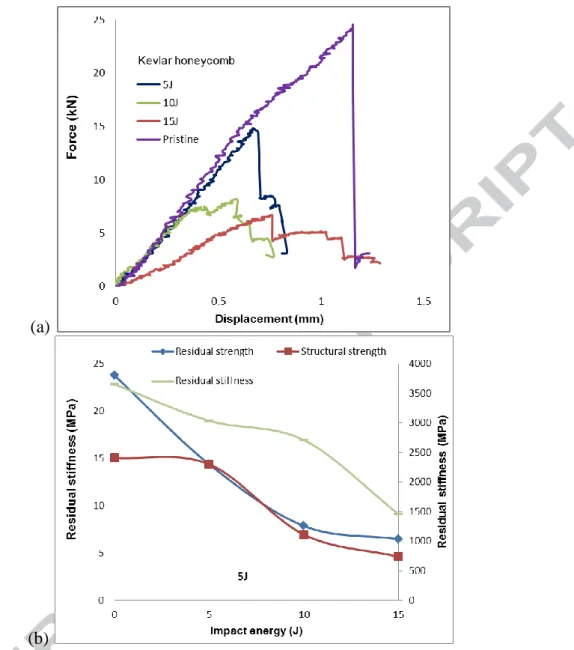
The overall load/displacement results and the strength reduction vs impact energy are shown in Figures 21 and 22, respectively. These sandwiches exhibit an exceptional and unexpected behavior with a drop in strength and in stiffness limited to less than 10 %, even for the 15 J impact. Moreover, as for the plywood with aluminum skins, a plateau area is observed. The failure scenario is also similar to that found in [13, 14] with a final brittle failure of the flax skin.
4.3. Summary
Compression After Impact tests results are presented in Figure 23 a, b, c & d in terms of force-displacement response for the nine different structures when pristine and after 5 J, 10 J and 15 J impact. Their main interest is that they enable comparisons to be made between the values at failure and the various behaviors. Strength reduction and normalized specific strength are presented for the nine different structures in Table 4 and Figure 24 a and b. Whatever the method of manufacture, in pristine state or impacted, it is the sandwich with fiberglass skins that resists the best, by a factor of 2. It is also the one made with the cheapest materials. Carbon skin sandwiches come after fiberglass sandwiches. This result is a little unexpected but the manufacturing method is not stabilized and, given the observed failure modes (buckling of the skins over a large surface area), it is likely that the bonding between skins and plywood is not yet optimum. For these two sandwiches, the method of manufacture is important and thermo-compression gives worse results than vacuum molding. For these four configurations, the rupture is fragile and the potential for use in crash energy absorption is limited.
Conversely, the reference sandwich, except in pristine condition, almost always has the lowest compressive strength, even compared to plywood alone. However, this can be explained by a density that is half that of the plywood specimens. Another peculiarity is that, at 15 J, the strength drop reaches 70% for this sandwich (Fig 24 a) and, from this point of view, this material is very poor.
Sandwiches with flax and aluminum skins have very similar and particularly interesting mechanical behaviors: they have a very large plateau area and a quasi-insensitivity to impact (see Fig. 24 a) with less than 10% reduction. For example, at 15 J, they are comparable to carbon skin sandwiches. For a sandwich to be effective in compression, the skins thus need to have a certain flexibility (like glass fibers) or a high plastic area, like flax or aluminum skins. In any case, it would be necessary to "tune" the skins to the plywood.
In Fig. 24 (b), the specific characteristics have been normalized with respect to the reference sandwich in the pristine state (see Table 4 calculations) and the results in this form are very interesting since the fiberglass skin sandwiches have a specific resistance 20% higher than the reference sandwich in compression in the pristine state. In this configuration, the other sandwiches are, on the other hand, about half as efficient. However, by 10 J, all sandwiches with a core in plywood become more efficient than the reference sandwich. Here, we find an intrinsic performance of the wood under this stress [40, 41] provided that it is confined, a role that is probably performed by the skins of the sandwich.
5. Conclusions
Compression and compression after impact of nine combinations of sandwiches with plywood cores, a reference sandwich commonly used for aircraft flooring, and plywood alone were investigated. The failure scenarios have been identified and are caused by breakages in the skin, often after local buckling. One of the most interesting points highlighted by this study is a long plateau for plywood, flax composite skin and aluminum skin structures, which
characterizes progressive damage in both pristine and impacted samples and shows great accommodation to the stress. These results suggest that ductile materials should be used in skins to dissipate a maximum of energy, especially for crash-type applications. Plywood structure with glass skin is found to provide the best compromise between residual strength and stiffness reduction, which may be explained by factors such as higher strength and thickness of the glass skin and better adhesion attained through the thermo-compression process, in which lower pressure is required for glass than carbon skin.
Plywood with flax skin, which could be produced from bio-resources, is identified as another good compromise solution based on factors such as residual stiffness, strength reduction, specific properties (stiffness and strength) and eco-aspects.
In general, these structures have a very good specific compressive strength and a very good specific compressive strength after impact, both of which are higher than in the reference sandwich. These results show that these structures with plywood cores have great potential for use in the transport field - and for a cost 20 times lower than the reference sandwich. Optimization is needed with regard to both stacking and the choice of plywood species, as well as with regard to the manufacturing methods and the bonding of skins to plywood in particular. A very strong potential also exists for weight reduction, by simply piercing the core of the plywood.
Acknowledgements
The authors would like to acknowledge the French Ministry of Education and Research for funding this study and AIRBUS for providing the reference materials.
References
[1] A Tropis, M Thomas, J L Bounie, P Lafon. Certification of the Composite Outer Wing of the ATR72. Proc Inst Mech Eng Part G: J. Aero Eng 1995;209(4):327-339.
[2] Christophe Bouvet. Mechanics of Aeronautical Composite Material. ISTE, Wiley, London 2017
[3] Abrate, Serge, Castanié, Bruno; Rajapakse, Yapa D. S. Dynamic Failure of Composite and Sandwich Structures, (Eds.) Springer 2013
[4] Xiong Y, Poon C., A prediction method for the compressive strength of impact damaged composite laminates, Comp Struct 1995;30:357–67.
[5] Naik NK, Ramasimha R. Estimation of compressive strength of delaminated composites, Comp Struct 2001;52:199–204.
[6] Qi B, Herszberg I., An engineering approach for predicting residual strength of carbon/epoxy laminates after impact and hygrothermal cycling, Comp Struct 1999 ;47:483– 90.
[7] Suemasu H, Sasaki W, Ishikawa T, Aoki Y., A numerical study on compressive behaviour of composite plates with multiple circular delaminations considering delamination propagation, Comp Sci Tech 2008;68:2562–7.
[8] De Moura MFSF, Gonçalves JPM, Marques AT, De Castro PMST., Modeling compression failure after low velocity impact on laminated composites using interface elements, J. Comp Mat 1997;31:1462–79.
[9] Hawyes VJ, Curtis PT, Soutis C., Effect of impact damage on the compressive response of composite laminates, Comp Part A 2001;32:1263–70.
[10] Yan H, Oskay C, Krishnan A, Xu LR., Compression-after-impact response of woven fibre-reinforced composites, Comp Sci Tech 2010;70:2128–36.
[11] González EV, Maimí P, Camanho PP, Turon A, Mayugo JA. Simulation of drop-weight impact and compression after impact tests on composite laminates, Comp Struct 2012;94:3364–78.
[12] Tan W, Falzon BG, Chiu L. N.S., Price M. Predicting low velocity impact damage and Compression-After-Impact (CAI) behaviour of composite laminates. Compo Part A 2015;71: 212–226
[13] Aminanda Y, Castanie B, Barrau JJ, Thevenet P. Experimental and numerical study of compression after impact response of sandwich structures with metallic skins, Comp Sci Tech 2009;69:50–59.
[14] Castanié B, Aminanda Y, Bouvet C, Barrau JJ. Core crush criterion to determine the strength of sandwich composite structures subjected to compression after impact. Comp Struct 2008;86(1-3):243-250.
[15] Cartie DDR, Irving PE. Effect of resin and fibre properties on impact and compression after impact performance of CFRP. Comp Part A 2002;33:483–93.
[16] Ishikawa T, Sugimoto S, Matsushima M, Hayashi Y., Some experimental findings in compression-after-impact (CAI) tests of CF/PEEK (APC-2) and conventional CF/epoxy flat plates, Comp Sci Tech 1995;55:349–63.
[17] Vieille B, Casado VM, Bouvet C. Influence of matrix toughness and ductility on the
compression-after-impact behavior of woven-ply thermoplastic-and
thermosetting-composites: a comparative study. Comp Struct 2014;110:207-218.
[18] Aymerich F, Priolo P., Characterization of fracture modes in stitched and unstitched cross-ply laminates subjected to low velocity impact and compression after impact loading, Int. J Impact Eng. 2008;35(7):591–608.
[19] Tan KT, Watanabe N, Iwahori Y, Ishikawa T., Effect of stitch density and stitch thread thickness on compression after impact strength and response of stitched composites, Comp Sci Tech 2012;72:587–98.
[20] Zhang X, Hounslow L, Grassi M., Improvement of low-velocity impact and compression-after-impact performance by z-fibre pinning, Comp Sci Tech 2006;66:2785–94. [21] Dale M, Acha BA, Carlsson LA., Low velocity impact and compression after impact characterization of woven carbon/vinylester at dry and water saturated conditions, Comp Struct 2012;94:1582–9.
[22] Kinsey A, Saunders DEJ, Soutis C., Post-impact compressive behaviour of low temperature curing woven CFRP laminates, Comp B 1995;26:661–7.
[23] Berketis K, Tzetzis D, Hogg PJ., The influence of long term water immersion ageing on impact damage behaviour and residual compression strength of glass fibre reinforced polymer (GFRP), Mat Design 2008;29:1300–10.
[24] Qi B, Herszberg I., An engineering approach for predicting residual strength of carbon/epoxy laminates after impact and hygrothermal cycling, Comp Struct 1999;47:483– 90.
[25] Petit S, Bouvet C, Bergeot A, Barrau JJ. Impact and compression after impact experimental study of a composite laminate with cork thermal shield, Comp Sci Tech 2007;67:3286–99.
[26] Zhang X, Davies GAO, Hitchings D., Impact damage with compressive preload and post-impact compression of carbon composite plates, Int. J Impact Eng 1999;22:485–509. [27] Ozdemir O, Oztoprak N, Kandas H. Single and repeated impact behaviors of bio-sandwich structures consisting of thermoplastic face sheets and different balsa core thicknesses Comp Part B. 2018;149:49-57.
[28] Atas C., Sevim C. On the impact response of sandwich composites with cores of balsa wood and PVC foam Compos. Struct., 93 (1) (2010), pp. 40-48
[29] Wen XZ, Huang J, Li Y, Chen P, Jiang L, Long Y, Liu S. Preliminary study on shielding
performance of wood stuffed shield. Int J. Imp Eng 2016;91:94–101
[30] Demircioğlu T.K., Balıkoğlu F., İnal, O., Arslan N., Ay A. A. Experimental investigation on low-velocity impact response of wood skinned sandwich composites with different core configurations. Mat Today Com 2018;17:31-39
[31] Balıkoğlu F., Demircioğlu T.K., İnal, O., N.Arslan, Ataş A. Compression after low velocity impact tests of marine sandwich composites: Effect of intermediate wooden layers. Comp Struct 2018;183:636–642
[32] Susainathan J, Eyma F, De Luycker E, Cantarel A, Castanié B. Manufacturing and quasi-static bending behavior of wood-based sandwich structures. Comp Struct 2017;182:487-504. [33] Susainathan J, Eyma F, De Luycker E, Cantarel A, Castanié B. Experimental investigation of impact behavior of wood-based sandwich structures. Comp Part A 2018;109:10-19.
[34] Susainathan J, Eyma F, De Luycker E, Cantarel A, Castanié B. Numerical Modeling of impact on wood-based sandwich structures. Mechanics of Advanced Materials and Structures, on line.
[35] John Prakash SUSAINATHAN. Development and characterization of Wood Based Eco-structure. PhD University of Toulouse 2017.
[36] Adam L, Bouvet C, Castanié B, Daidié A, Bonhomme E. Discrete ply model of circular pull-through test of fasteners in laminates Comp Struct 2012;94(10):3082-3091
[37] B Castanié, JJ Barrau, JP Jaouen, S Rivallant Combined shear/compression structural testing of asymmetric sandwich structures. Experimental mechanics 2004 44 (5), 461-472
[38] Aminanda Y, Castanie B, Barrau JJ, Thevenet P. Experimental analysis and modeling of the crushing of honeycomb cores. Appl Comp Mat 2005;12(3-4):213-217.
[39] Castanié B, Bouvet C, Aminanda Y, Barrau JJ, Thevenet P. Modelling of low energy/low velocity impact on Nomex honeycomb sandwich structures with metallic skins. Int J. Imp Eng 2008;35:620-634.
[40] Wouts J., Haugou G., Oudjene M., Coutellier D., Morvan H. Strain rate effects on the compressive response of wood and energy absorption capabilities – Part A: Experimental investigations Comp Struct 2016;149:315-328
[41] Wouts J., Haugou G., Oudjene M., Coutellier D., Morvan H. Strain rate effects on the compressive response of wood and energy absorption capabilities – Part B: Experimental investigation under rigid lateral confinement Comp Struct 2018;204:95-104.
Figures
(a) (b)
(c)
Figure 2: Compression After Impact test, a) On front side using stereo correlation, b) On rear side using LVDT, c) Whole test set-up
Figure 3: Force – displacement responses of sandwiches with plywood cores.
(a)
(b)
(a)
(b)
Figure 6: Evolution of mechanical characteristics vs impact energy for plywoods A (a) and B (b).
(a)
(b)
Figure 7: Out of plane displacement of pristine specimen of plywood A (a) along compression direction (X) and vs load, and (b) final failure pattern.
(a)
(b)
Figure 8: Out of plane displacement of pristine specimen of plywood B (a) along compression direction (X) and vs load, and (b) final failure pattern.
(a) (b)
(c)
Figure 9: Typical failure pattern for CAI of plywood A (a) and (b) impacted at 15 J, and out of plane displacement of specimen impacted at 5 J for plywood B (c) along compression direction (X).
(a)
(b)
Figure 10: Test results (a) and evolution of mechanical characteristics (b) for reference sandwich.
(a)
(b)
Figure 11: Tests results (a) and evolution of mechanical characteristics (b) for sandwiches with plywood A core and aluminum skins.
0 1000 2000 3000 4000 5000 6000 7000 8000 0 5 10 15 20 25 30 35 0 5 10 15 R esi dual st if fness (M Pa) S treng th (M P a) Impact energy (J) Residual strength Structural strength Residual stiffness (a)
(a)
(b)
Figure 12: Skin buckling for the pristine specimen (a) and failure pattern for impacted specimen (b)
(a)
(b)
Figure 13: (a) overall shape of plywood-aluminum under compression after impact and (b) evolution of out-of-plane displacement for the median axis.
Skin wrinkling and failure
(a)
(b)
(a)
(b)
Figure 15: Evolution of mechanical characteristics for sandwiches of plywoods A (a) and B (b), with carbon skins.
Figure 16: Typical local skin buckling for plywood with carbon skins.
Figure 17: Out-of-plane displacement of plywood A with carbon skins during CAI after a 15 J impact.
Figure 18: Test results for sandwiches with plywood B and glass skins.
Figure 19: Evolution of mechanical characteristics for sandwiches with plywood A and glass skins.
(a) (b)
Figure 20: For the 15 J impacted specimen of plywood A with glass skin: a) local buckling of the skin and b) failure pattern.
Figure 22: Evolution of mechanical characteristics for sandwiches with plywood A and flax skins.
(a)
(c)
(d)
Figure 23: Overall compression force vs displacement curves for the nine configurations of sandwiches when pristine (a) or impacted at 5 J (b), 10 J (c) or 15 J (d)
(a)
(b)
Figure 24: Strength reduction and specific performance of the nine sandwich configurations.
Tables
Table 1: Plywood A and B stacking.
Core Skin Process Relative
density Total Thickness (mm) Process specification Plywood A - - 0.461 10 -Plywood B - - 0.433 10 -Plywood A Aluminum - 0.678 11 -Plywood A
Glass Vacuum bag molding -
Prepreg
0.638
12
At 160 °C for 3 hr
Carbon 0.569 At 90 °C for 30 min then at 125 °C for 1 hr Plywood B Flax Thermo-compression - Prepreg 0.488 12 At 120 °C with pressure of 4 bar for 1 hr Carbon 0.614
At 90 °C for 30 min then at 120 °C for 1 hr, all with pressure of 4 bar
Glass 0.609 At 160 °C with pressure of 4 bar for 3 hr
Materials Impact Pristine No. of samples in CAI 5 J 10 J 15 J Plywood - A 1 1 1 1 4 Plywood - B 2 2 2 1 4 Plywood - A / Aluminum 2 2 2 1 4 Vacuum Molding Plywood - A / Glass 1 1 1 1 4 Plywood - A / Carbon 1 1 1 1 4 Thermo-compression Plywood - B / Flax 1 1 1 1 4 Plywood - B / Carbon 1 1 1 1 4 Plywood - B / Glass 1 1 1 1 4 HC Aramid / carbon 1 1 1 1 4
Table 3: Test Matrix for CAI tests.
Table 4: Summary of strengths for the nine sandwich configurations.
Density (kg/m3)
New 5 10 15 0 5 10 15 0 5 10 15
Compressive strength (MPa) Specific strength (MPa.m3/kg) Normalized Specific strength
0.39 17.9 17.7 17.0 12.1 0.0485 0.0402 0.55 0.52 0.48 461.0 0.0562 0.0527 24.3 22.4 18.5 25.9 0.40 0.40 0.38 0.27 31.6 433.0 0.0413 0.0410 0.0391 0.0279 45.3 0.42 66.0 64.1 50.3 0.0457 0.0425 0.46 0.45 0.45 678.0 0.0466 0.0465 31.5 31.0 28.8 1.12 1.08 0.85 0.77 579.0 0.1140 0.1108 0.0868 0.0782 24.2 23.5 0.58 0.40 25.5 24.2 0.0594 0.0588 0.0406 0.61 0.58 638.0 0.0627 40.0 37.9 37.5 25.9 0.0382 0.41 0.39 0.39 0.37 614.0 0.0415 0.0394 0.0394 0.38 60.7 44.2 40.1 39.7 0.0431 0.0390 0.54 0.43 0.42 609.0 0.0556 0.0442 26.9 26.2 23.7 33.9 0.80 23.8 488.0 0.1244 0.0907 0.0821 0.0814 14.4 7.87 6.48 1.22 0.89 0.80 0.27 0.0338 0.0278 1.00 0.61 0.33 233.0 0.1021 0.0618 Plywood B/ Flax Plywood B/ Carbon Plywood B/ Glass Reference Sandwich Materials Plywood B Plywood A/Al Plywood A/Glass Plywood A/ carbon Plywood A
![Figure 4: Structural strength (or failure [36]) and residual strength.](https://thumb-eu.123doks.com/thumbv2/123doknet/2959310.81247/22.892.104.754.217.939/figure-structural-strength-failure-residual-strength.webp)