HAL Id: hal-02115619
https://hal-univ-rennes1.archives-ouvertes.fr/hal-02115619
Submitted on 9 Nov 2020
HAL is a multi-disciplinary open access
archive for the deposit and dissemination of
sci-entific research documents, whether they are
pub-lished or not. The documents may come from
teaching and research institutions in France or
abroad, or from public or private research centers.
L’archive ouverte pluridisciplinaire HAL, est
destinée au dépôt et à la diffusion de documents
scientifiques de niveau recherche, publiés ou non,
émanant des établissements d’enseignement et de
recherche français ou étrangers, des laboratoires
publics ou privés.
Immune-to-Detuning Wireless In-Body Platform for
Versatile Biotelemetry Applications
Denys Nikolayev, Maxim Zhadobov, Ronan Sauleau
To cite this version:
Denys Nikolayev, Maxim Zhadobov, Ronan Sauleau. Immune-to-Detuning Wireless In-Body Platform
for Versatile Biotelemetry Applications. IEEE Transactions on Biomedical Circuits and Systems,
Insti-tute of Electrical and Electronics Engineers, 2019, 13 (2), pp.403-412. �10.1109/TBCAS.2019.2892330�.
�hal-02115619�
Immune-to-detuning Wireless In-body Platform
for Versatile Biotelemetry Applications
Denys Nikolayev, Member, IEEE, Maxim Zhadobov, Senior Member, IEEE, and Ronan Sauleau, Fellow, IEEE
Abstract—Background and Objective: In-body biotelemetry de-vices enable wireless monitoring of a wide range of physiological parameters. These devices rely on antennas to interface with external receivers, yet existing systems suffer from impedance detuning caused by the substantial differences in electromagnetic properties among various tissues. In this paper, we propose an immune-to-detuning in-body biotelemetry platform featur-ing a novel tissue-independent antenna design. Methods: Our approach uses a novel slot–patch conformal antenna integrated into a flexible polyimide PCB containing the device circuitry and encapsulated within a 17.7 mm × 8.9 mm biocompatible shell. The antenna is synthesized and optimized using a hybrid analytical–numerical approach, then characterized numerically and experimentally in terms of impedance stability. Results: The proposed platform shows stable impedance whereas operating in any mammalian tissue as well as in air. The system is optimized for the 434 MHz ISM band and can easily be returned for any MedRadio band in the 401–457 MHz spectrum. Conclusion: Ultra-robust impedance characteristics were achieved. Without any modifications, the proposed biotelemetry platform can be used, for instance, as an ingestible for humans or as an im-plantable for a wide range of animals: from rodents to cattle.
Index Terms—biomedical telemetry, conformal antennas, im-plantable, in-body, ingestible, ISM (industrial, scientific, and medical) band, MedRadio band, robust antennas.
I. INTRODUCTION
I
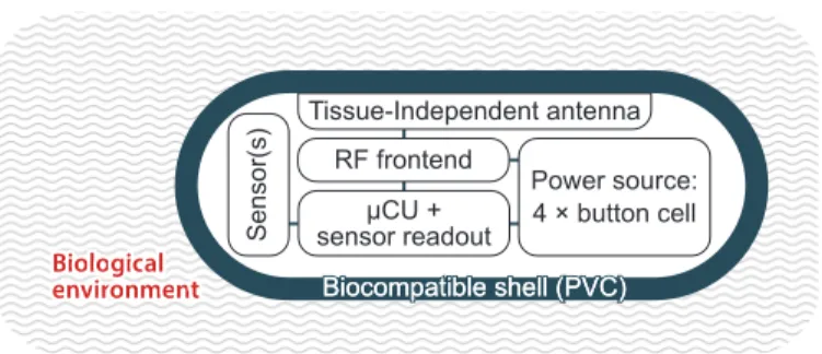
NGESTIBLE and implantable (in-body) devices for biomedical telemetry (Fig. 1) provide powerful capabilities in medicine, clinical research, sports, and occupational health [1]–[4]. In-body devices allow for continuous monitoring of various physiological parameters, namely intracorporal tem-perature, pressure, pH, glucose, hormone, antibody levels, endoscopic imagery, and so on.In-body biotelemetry devices rely on radiofrequency (RF) antennas to interface with external systems. The antenna performance strongly depends on dispersive electromagnetic
Manuscript received September 13, 2018.
This work was supported in part by the BodyCap Company, in part by the French National Center for Scientific Research and Directorate General of Armaments through the PEPS program, in part by Rennes Metropole through the AES program, and in part by the French Ministry of Foreign Affairs and International Development through the Eiffel Scholarship. (Corresponding author: Denys Nikolayev.)
D. Nikolayev is with the Imec / Ghent University, 9052 Gent, Belgium and also with the Institute of Electronics and Telecommunications of Rennes, UMR CNRS 6164, University of Rennes 1, 35042 Rennes, France (e-mail: [email protected])
M. Zhadobov and R. Sauleau are with the Institute of Electronics and Telecommunications of Rennes, UMR CNRS 6164, University of Rennes 1, 35042 Rennes, France. RF frontend Tissue-Independent antenna Power source: 4 × button cell µCU + sensor readout Biocompatible shell (PVC) Biocompatible shell (PVC) Sensor(s)
Fig. 1. Outline of the wireless pill-shaped device for biotelemetry. Tissue-independent antenna design ensures the detuning immunity.
(EM) properties ˆε (ω) = ε0(ω) + jε00(ω) of surrounding tissues [5], where ε0 is the real part of the permittivity, ε00 is the imaginary part of the permittivity, and ω is the angular frequency. The radiated wave undergoes attenuation due to tissue losses (characterized by ε00 = σ/ω, were σ is the conductivity) and scattering because of tissue heterogeneity ˆ
ε (r, ω) [6]. Another factor limiting the antenna performance is its impedance ZA(ˆε, ω) detuning caused by varying EM
properties ˆε (r, ω) of biological tissues (Table I) [7]. The wider is the range of tissue EM properties that the antenna can handle (i.e. matching remains below |S11| ≤ −10 dB), the more it is
considered robust.
Designing an in-body device that can operate from any tis-sue (i.e. ultra-robust) allows for its application in a wide range of scenarios. For instance, the same wireless temperature-telemetry capsule (e.g. BodyCap e-Celsuis [8]) can be used as an ingestible for humans and as an implantable for animals that can range in size from a mouse to a cow.
The majority of existing in-body capsule antennas are designed for a specific application (ingestible, subcutaneous, osseous, and so on) [9]–[12], whereas the robustness is ensured only within a target application. For ingestible applications, this includes analyzing the antenna performance in stomach, small intestine, and colon (Table I). Magill et al. [13] pro-posed a 2.45 GHz tissue-independent antenna that shows good matching (|S11| < −10 dB) in all high-water-content tissues as
well as a satisfactory matching in fat (|S11| ≈ −7.5 dB). Yet,
this design requires thick ceramic substrate and superstrate, thus making it inapplicable for capsule-conformal applications. A robust capsule-conformal microstrip antenna has been pro-posed in [14]. However, it detunes in fat (|S11| ≈ −3 dB) and
requires costly ceramic superstrate.
Here, we propose an immune-to-detuning in-body
plat-1 2 3 4 5 6 7 8 9 10 11 12 13 14 15 16 17 18 19 20 21 22 23 24 25 26 27 28 29 30 31 32 33 34 35 36 37 38 39 40 41 42 43 44 45 46 47 48 49 50 51 52 53 54 55 56 57 58 59
2 IEEE TRANSACTIONS ON BIOMEDICAL CIRCUITS AND SYSTEMS, VOL. PP, NO. X
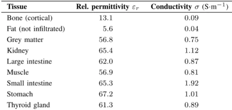
TABLE I
ELECTROMAGNETIC PROPERTIES
OF DIFFERENT TISSUES AND ORGANS AT434 MHZ[7]
Tissue Rel. permittivity εr Conductivity σ (S·m−1)
Bone (cortical) 13.1 0.09
Fat (not infiltrated) 5.6 0.04
Grey matter 56.8 0.75 Kidney 65.4 1.12 Large intestine 62.0 0.87 Muscle 56.9 0.81 Small intestine 65.3 1.92 Stomach 67.2 1.01 Thyroid gland 61.3 0.89
form based on an ultra-robust antenna that maintains stable impedance whereas operating in any mammalian tissue as well as in air. The latter makes it possible to communicate with the device prior to its ingestion or implantation. In addition, it ensures the operation in respiratory system, for instance.
The paper is organized as follows. Section II starts by theoretical considerations, then it describes the choice of materials and the ultra-robust antenna synthesis approach. Section III deals with the numerical analysis, and Section IV provides the experimental validation. Conclusions are drawn in Section V.
II. WIRELESSIN-BODYPLATFORMDESIGN
A. Theoretical Considerations
First, we defined the operating frequency according to prior theoretical studies [6], [15], [16]. The optimal frequency range (i.e. where the radiation efficiency is on its peak) depends, among others, on the depths of the antenna in a body. Generally, the closer the antenna is to the surface, the higher the optimal frequency. Considering both deep-body and subcutaneous applications, we chose to design the antenna for the 434 MHz ISM (Industrial, Scientific, and Medical) band [17]. As shown ahead in Section III-A1, an adjustment can retune the antenna to any MedRadio (Medical Device Radiocommunications Service) band as well [18].
To be ultra-robust, the antenna must be insensitive to its environment—in other words, remain matched with |S11| <
−10 dB at the operating frequency f0. The environment
con-sists of biological tissues having a wide range of EM properties that, according to Gabriel et al. [7], may vary as εr∈ [5.6..80],
σ ∈ [0..2.4] S·m−1 at 434 MHz. The operating environment may also include air for some application scenarios (e.g. in lungs or trachea). Moreover, some in-body devices usually require an activation (in air) prior to implantation or ingestion. In addition, they can be designed to operate in the respiratory system. Therefore, the range of relative permittivity extends to εr∈ [1..80].
Tissue losses significantly affect the radiation performance of in-body antennas. High-permittivity capsule shells (mostly made of low-loss perovskite-type ceramic materials) mitigate the losses in near field [19], [20]. However, high material costs limit the scope of potential applications and make the
y x z y x z Coplanar section in ground plane Microstrip feed PVC shell VIA ⌀8.9 17.7 l1 l2 ⌀7.6 ⌀100 Capsule Muscle-equivalent phantom low Z1 high Z2 (a) (d) (e) (f) (b) (c) low Z1 ground plane substrate high Z2 VIA VIA l2 l1
Fig. 2. Geometry and building blocks of the proposed capsule antenna (mm). (a) The antenna conforming to the inner surface of a 0.65-mm-thick PVC shell. (b) Theoretical representation: a quarter-wave stepped-impedance resonator. (c) Foldable microstrip feed connecting the antenna to the PCB (not shown). (d), (e) Top and bottom views, respectively, of the planar geometry of the
antenna (l1= 4.5, l2= 4.2). (f) Simulation setup in CST MWS.
mass production impossible. Using low-cost materials (usually, lower-permittivity biocompatible plastics) results in stronger antenna coupling to the adjacent lossy tissues. Sections of microstrip antennas with high characteristic impedance (high-Z) are the most affected by this due to broader fringing fields
1 2 3 4 5 6 7 8 9 10 11 12 13 14 15 16 17 18 19 20 21 22 23 24 25 26 27 28 29 30 31 32 33 34 35 36 37 38 39 40 41 42 43 44 45 46 47 48 49 50 51 52 53 54 55 56 57 58 59
that penetrate into the tissues. This coupling substantially reduces the antenna robustness. Therefore, we conjectured that realizing the high-Z section as a coplanar line in the ground plane of the antenna would move the fringing fields inside of the practically lossless capsule and away from the tissues. This helps reducing the variance of effective EM properties Var (ˆε) in the near-field zone of the antenna hence results in improved robustness.
The reader is warned that this configuration per se would backfire with reduced radiation efficiency η (compared to counterparts) due to, in particular, increased current symmetry and high wave-impedance contrast between the capsule envi-ronment and tissues. To partially mitigate these effects, we considered the following. First, as we deal with electrically small antennas (ESA) in lossy media (ka < 0.5, where k is the wavenumber and a is the antenna circumradius), enlarging the antenna size increases its theoretically achievable radiation efficiency ηmax ∝ ka/FBW [21], [22], where FBW is the
half-power fractional bandwidth. Therefore, we maximized the antenna circumradius a by spanning it along the whole length of a cylindrical section of the capsule (8.8 mm, Fig. 2). Second, filling the capsule with a low-loss material having its relative permittivity εr> 1 loads the antenna and further
in-creases its electrical size ka as k ∝√εr [14]. Third, avoiding
meandering of the high-Z section (Fig. 2b) may increase the net current on the section and improve the radiation efficiency. Finally, keeping the substrate as thick as possible improves the radiation efficiency as well [23]. The maximum thickness is restricted though by mechanical constraints, as the printed-circuit board (PCB) requires bending and folding. Fig. 2c shows the bending of the microstrip feed in order to reach the RF frontend.
B. Materials
1) Printed Circuit Board: The proposed antenna integrates on the same PCB as the capsule circuitry. In this way, the antenna is patterned in one process with the circuitry thus minimizing manufacturing costs. The copper-clad substrate is made of polyimide with εr = 3.4, tan δ = 0.002 and
can vary in its thickness from 25.4 µm to 152.4 µm with a 25.4 µm increment. After evaluating the mechanical stress due to folding, the thickness of the substrate was set to 50.8 µm. Hypothetically, one can improve this design by using a substrate with variable thickness—minimal for the circuitry (that requires folding) and maximal for the antenna (that performs better on a thicker substrate). In practice, this approach substantially increases manufacturing cost that limits the scope of applications of the antenna.
2) Encapsulation: The antenna conforms to the inner sur-face of a 0.65-mm-thick biocompatible capsule shell. The overall dimension of the shell are 17.7 mm × 8.9 mm (Fig. 2a). It is made of PVC with additives to improve mechanical properties; the dielectric properties were initially unknown. In contrast to ceramic shells, the plastic one allows for mass production through low material and process costs. This, however, comes at a price of reduced radiation efficiency.
3) Capsule filling: Filling the capsule with a solid dielectric material helps preserving its structure integrity, increases the electrical size of the antenna, and improves wave-impedance matching with the surrounding tissues. In addition, leveling permittivities of the superstrate and filling reduces the manu-facturing tolerance requirements on how tight the antenna has to conform to the superstrate. In this paper, we use a biocom-patible bi-component epoxy resin. As for the encapsulation PVC, the dielectric properties were initially unknown.
4) Characterization of materials: To determine dielectric properties of the PVC and the epoxy, we measured its com-plex permittivity in the 100-MHz-to-6-GHz band using a transmission/reflection method. The bulk materials (≥ 24h-cured epoxy) were milled into the 2-mm-thick washers (ext. 7 mm ±10 µm, int. 3.04 mm ±10 µm) and fitted within an APC-7 coaxial line that was connected to a vector network an-alyzer (VNA). After post-processing the results, the measured dielectric properties at 434 MHz are: εr= 2.6, tan δ = 0.003
for the PVC and εr= 3.1, tan δ = 0.037 for the epoxy.
The final device containing the circuitry and batteries weights about 2 g (measured) that makes it usable for a wide range of implantable and ingestible applications.
C. Antenna Synthesis
Integrating a 434-MHz antenna (λ0/2 ≈ 34 cm) within
an 8.8-mm-long cylindrical section of the capsule (Fig. 2a) requires reducing its length to about 3% of a conventional patch antenna. Surrounding tissues having high effective rel-ative permittivity εeffr load the antenna. This increases the
electrical size of the antenna and therefore reduces the neces-sary miniaturization up to a factor of pεeff
r . For further size
reduction, we shorted the antenna and intoduced an impedance discontinuity [24]. Fig. 2b outlines the theoretical structure of the antenna that consists of two transmission lines Z1 and
Z2 of lengths l1 and l2, respectively. Neglecting the fields at
discontinuities, the transmission-line-impedance equation [25, p. 59] enables straightforward modeling of the antenna. For the structure depicted on Fig. 2b, the model becomes (full derivation is given in [26]): ( −Z1+ Z2tan (β2l2) tan (β1l1) = 0 Z2tan (β1l1) + Z1tan (β2l2) 6= 0 βn= 2π c fres q εeff r,n, n = 1, 2 (1)
where Zn(n = 1, 2) are the characteristic impedances of each
section, βn are the phase constants, ln are the section lengths,
c is the speed of light in vacuum, and εeff
r,n are the effective
relative permittivities of media surrounding each section. Characteristic impedances Zn along with corresponding
εeff
r,n can be evaluated numerically [27] on 2D cross-sections
of each line taking into account the effects of both antenna conformability and dielectric loading [28]. Fig. 2d illustrates the microstrip low-Z1element patterned on the PCB top layer,
and Fig. 2e depicts the coplanar high-Z2element etched from
the bottom layer. The elements couple by means of a via. To synthesize the antenna, we began by reducing the solution space of (1) by applying the following constrains:
1 2 3 4 5 6 7 8 9 10 11 12 13 14 15 16 17 18 19 20 21 22 23 24 25 26 27 28 29 30 31 32 33 34 35 36 37 38 39 40 41 42 43 44 45 46 47 48 49 50 51 52 53 54 55 56 57 58 59
4 IEEE TRANSACTIONS ON BIOMEDICAL CIRCUITS AND SYSTEMS, VOL. PP, NO. X
1) l1+ l2 = const. as the antenna has to span all available
space within the cylindrical part of the capsule; 2) Z1is set to
its minimum value by taking all available width of the PCB extension; and 3) the width of the central conductor of Z2was
fixed to 100 µm. In this way, the antenna fine-tuning reduces to one parametric dimension—the width of the coplanar slots. A microstrip feed connects the antenna to an RF frontend (Fig. 2c). Taking into account the low characteristic impedance of Z1 and its small electrical length, we can connect the
feed to the longitudinal edge of Z1 without any noticeable
effect neither on the input impedance of the antenna nor its polarization purity. The longitudinal configuration relieves the mechanical stress on the substrate compared to the transverse feed proposed in [14].
D. Circuit Design
The antenna connects to a wireless microcontroller with sensor readout capabilities (µCU) via an RF frontend. Taking into account the operating frequency of 434 MHz, we chose to use the Si-10XX µCU family because of its small footprint (QFN36 package, 5 × 6 mm2), 13 dBm input power (up to 20 dBm), and high Rx sensitivity (−126 dBm).
The µCU requires a matching circuit to transform the antenna impedance to a single-ended Tx pin and differential Rxp/Rxnpins. As the transformation is required independently
of the antenna impedance, there is no need for the design to have 50 Ω at f0. After evaluating the antenna impedance
numerically (Section III) and validating experimentally (Sec-tion IV), we tuned a 7-element matching network with direct-tie topology. It contains an L-type matching circuit for Tx, a 3-element C1–L–C2 for Rx, and a 434-MHz LC resonator
tank. In addition to the conjugate matching, this configuration filters out higher harmonics generated by the power amplifier. The final capsule prototype contains a thermocouple sensor for intracorporal temperature telemetry [29]. The power source is four button cell batteries.
III. NUMERICALANALYSIS
After defining the initial geometry using (1), we fine-tuned and analyzed the antenna in CST Microwave Studio 2017 [30] (CST MWS). As the theoretical model takes into account the effects on resonance frequency of both tissue and curvature, we proceeded straight to the capsule-conformal antenna model (Fig. 2a) omitting the planar analysis stage. We used the frequency domain solver of CST MWS (finite element method) as more suitable for resolving the geometry of a low-profile conformal antenna. Adaptive mesh refinement used δ|S11| <
1% for two consecutive passes as a convergence criterion. To improve the mesh quality and thus the convergence, we pre-meshed top and bottom copper layers with 0.1 mm max-step width. The copper layers were modeled as thin sheets (impedance boundaries) having σ = 5.96 × 10⁷S·m−1. Other EM properties of the antenna materials were set as given in Section II-B.
The proposed antenna is designed to reliably operate from any location within a human or animal body. Therefore, analyzing it in an anatomical phantom is impractical, as one
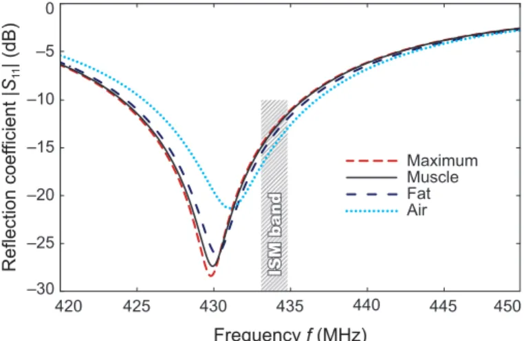
–30 –25 –20 –15 –10 –5 0 420 425 430 435 440 445 450 Reflection coef ficient | S11 | (dB) Frequency f (MHz) ISM band Maximum Muscle Fat Air
Fig. 3. Reflection coefficient |S11| of the proposed antenna computed in air
and in a 100-mm spherical phantom with various EM properties.
–30 –40 –50 –60 –70 dB(maxV/m) A/m(log) –80 0 20000 11100 5764 2565 648 Phantom Shell Epoxy Z1 (a) (b) z x y x
Fig. 4. Fields of the antenna at 434 MHz. (a) |E|-field (dBmax) distribution
on the x–z plane orthogonal to Z2 section (2 mm from Z1–Z2transition).
(b) Surface current distribution log (I) (A·m−1) for the phase ϕ = 90◦.
cannot predict all potential implantation sites. Instead, one should use a well-characterized canonical phantom that will make it possible to reproduce the results in measurements. Here, we used the isotropic canonical phantom set-up defined in [31]: the antenna is centered inside of a 100-mm spherical homogeneous phantom with various EM properties depending on the stage of analysis (Fig. 2f). The spherical symmetry conserves the intrinsic radiation pattern of the antenna inde-pendently of its orientation.
To maximize the antenna robustness both to the surrounding environment and inner circuitry, we tuned it in the environment with the highest overall EM properties of body tissues [7]. Here, the goal was to cross |S11| = −10 dB level at
434.8 MHz (upper bound of mid-ISM) such that all mid-ISM frequencies would be below |S11| < −10 dB (Fig. 3). In this
way, we establish the lowest possible fres, which would shift
upwards in all other tissues and in air (as the electrical size of an antenna is proportional to the effective permittivity of its surrounding medium).
A. Antenna Performance
and Robustness to Surrounding Media
Fig. 3 gives the impedance characteristics of the antenna (150-Ω normalization) when computed in the 100-mm spher-ical phantom with its EM properties corresponding to various media (Table I). In the muscle-equivalent phantom, fres =
430.1 MHz and BW = 11.9 MHz (or FBW = 2.8%). As the antenna is electrically small, it has an omnidirectional
1 2 3 4 5 6 7 8 9 10 11 12 13 14 15 16 17 18 19 20 21 22 23 24 25 26 27 28 29 30 31 32 33 34 35 36 37 38 39 40 41 42 43 44 45 46 47 48 49 50 51 52 53 54 55 56 57 58 59
radiation pattern (directivity D = 2.14 dBi). The realized gain is max (G) = −34 dBi. In fat (the lowest overall EM properties of body tissues, Table I), fres = 431 MHz. As
the antenna is resonant, and the EM properties (εr, σ) of
all remaining body tissues fit within the fat and the overall maximum [7], we can conclude that |S11| < −10 dB ∀fISM434
for all body tissues. In addition, the antenna stays well matched in air, which is, to the best of our knowledge, the first of its kind. The resonant frequencies for all aforementioned media are lower than ISM 434 MHz that allows one compensating for the detuning caused by inner components of the capsule.
Fig. 4a shows the near-field distribution (|E|) of the antenna around the Z2section. The electric field is enfolded around the
central conductor of Z2that helps to concentrate the near field
in the capsule shell. This helps to reduce the power dissipation in tissues and to lower the electromagnetic interference with circuitry. In such configuration, the antenna radiates primarily due to non-conserved current and charge in the region of space localized around Z2[32]. Hence, the magnitude of the current
in the central conductor of Z2 is substantially larger than
the one of the opposite current flowing in the ground plane (Fig. 4b).
1) Tuning the Operating Frequency: The wider the slots of Z2section are, the higher the characteristic impedance Z2.
Ac-cording to (1), the resonance frequency of the antenna would decrease as well. This can be used to fine-tune the antenna if the operating frequency must be adjusted within reasonable limits: for instance, to operate in one of MedRadio bands (401–406 MHz, 413–419 MHz, 426–432 MHz, 438–444 MHz, and 451–457 MHz) [18]. In addition, fres adjustment may be
required if the capsule materials or dimensions change. We varied the slot width ws to quantify its effect on the
complex antenna impedance ZA. The width of the central
conductor was fixed to 100 µm, and ws∈ [50..250] µm. Fig. 5
shows how the resonance frequency depends on ws. Within
the studied range of widths, the fres can be tuned to convert
the antenna to any MedRadio band [18]. The antenna gain is proportional to ws; max [G (ws= 250)] = −31 dBi that
is 3 dBi higher than for the default width ws = 100 µm. A
cautionary remark: as the radiation resistance of the antenna rises with the radiation efficiency [33], < (ZA) is proportional
to wsas well (Fig. 5). An adjustment of a matching circuit of
the antenna would be therefore required.
2) Robustness to Inner Components: An in-body biotelemetry capsule contains various electronic and biomedical circuits, sensors, and a power source. Up to this point, we have not considered how these inner components may affect the antenna impedance performance. The ground plane partially shields a capsule conformal antenna [14] enhancing its robustness. However, the fringing fields below Z2 may couple to the components affecting the
antenna impedance. A well-established approach to evaluate the effect of the inner components on the antenna impedance consists in introducing a perfect electric conductor (PEC) cylinder to the capsule model and vary its radius and/or position [10], [12], [14].
As the inner components can vary depending on application, we sought the worst-case scenario of an arrangement that
120 140 160 180 200 220 240 370 390 410 430 450 470 50 100 150 200 250 Impedance Re[ ZA (fres )] (Ω) Frequency fres [Im (ZA ) = 0 ] (MHz ) Slot width ws (µm) x y ws 100 µm
Fig. 5. Adjusting the operating band of the proposed antenna: effect of the
coplanar slot width wson antenna complex impedance ZA (inset shows the
geometry of the coplanar segment Z2, ws= 200 µm).
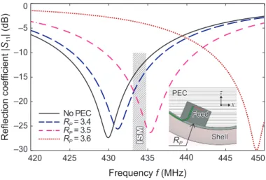
–30 –25 –20 –15 –10 –5 0 420 425 430 435 440 445 450 Reflection coef ficient | S11 | (dB) Frequency f (MHz) ISM No PEC RP = 3.4 RP = 3.5 RP = 3.6 z x PEC Feed Shell RP
Fig. 6. Effect of capsule inner components on the antenna performance:
computed reflection coefficients |S11| for various radii of a PEC cylinder
spanning the full length of the antenna. The inset shows the PEC cylinder
(RP= 3.6 mm) with a pocket to accommodate the waveguide port.
detunes the antenna by: 1) introducing a PEC cylinder of a radius RP spanning the whole length of the antenna (9 mm,
Fig. 2a) and 2) performing a parametric sweep over RP to
determine the maximum safe distance dP between the PEC
cylinder and the antenna. For RP < 3.3 mm (dP = 450 µm),
no effect on the antenna impedance was observed. As RP
increases and the PEC cylinder approaches the antenna, the resonance frequency of the antenna shifts up. Fig. 6 shows how reflection coefficient |S11| responds to the proximity of the
inner components for RP ≥ 3.4 mm. The proposed antenna
stays matched below |S11| < −10 dB until RP ≈ 3.5 mm
(dP ≈ 250 µm).
An electric conductor approaching the co-planar section of the antenna reduces its characteristic impedance Z2. Indeed,
we shall see from (1) that it results in the fres rising. One
can overcome this limitation on dP by stacking bulky
compo-nents (batteries, for instance) underneath the low-Z1 section
(Fig. 2d). Here, the ground plane fully shields the antenna mitigating the risk of impedance detuning.
1 2 3 4 5 6 7 8 9 10 11 12 13 14 15 16 17 18 19 20 21 22 23 24 25 26 27 28 29 30 31 32 33 34 35 36 37 38 39 40 41 42 43 44 45 46 47 48 49 50 51 52 53 54 55 56 57 58 59
6 IEEE TRANSACTIONS ON BIOMEDICAL CIRCUITS AND SYSTEMS, VOL. PP, NO. X
(a) (b) (c) (d)
Fig. 7. Capsule antenna prototype. (a) Planar antenna integrated with the
circuitry on the same polyimide substrate (proprietary circuitry blurred) and connected to a semi-rigid coaxial cable for measurements. (b) Final capsule mockup containing the antenna, circuitry, and filled with epoxy resin. (c) Nine prototypes were manufactured to ensure reproducibility. (d) Mockup and the final device without caps showing the alignment of circuitry.
IV. PROTOTYPING ANDMEASUREMENTS
Fig. 7 outlines the assembly process of the capsule. The antenna was integrated on the extension of a flexible 50-µm-thick polyimide PCB (flex) containing the capsule circuitry and batteries (Fig. 7a). Copper layers were patterned using photolithography. A 16-µm-thick polyimide coverlay was ap-plied to both top and bottom layers of the flex. As the relative permittivity of polyimide closely matches that of the epoxy, this configuration does not detune the antenna. Moreover, it protects the design—especially the feed and coplanar Z2
section—from accidental mechanical damage while assem-bling the capsule mockup (Fig. 7b). The flex was designed in such a manner that after folding it there remains at least 0.5-mm gap between the batteries (Fig. 7a) and the coplanar Z2section. In this way, the antenna is not detuned by the inner
components (Fig. 6).
To characterize the antenna in terms of its impedance and robustness with a VNA, we used a 100-mm-long semi-rigid coaxial cable terminated with an SMA connector. First, the antenna feed was cut out from the flex and the cable was soldered to a specially designated test pads (Fig. 7a). Second, the white part of the PVC capsule shell (Fig. 7b) was incised to pull the feed through the shell. Third, the flex was folded and inserted into the shell, and the feed was reinforced using the Araldite 2011 epoxy (Fig. 7b). Finally, the capsule was filled with a bi-component epoxy, outgassed, sealed, and cured for 24 hours. Nine prototypes were manufactured to ensure reproducibility (Fig. 7c).
The capsule antennas were characterized in three media: a muscle-equivalent liquid phantom, pure water, and air. To achieve the target EM properties of the muscle-equivalent phantom (εr = 56.9, σ = 0.81 S·m−1 at 434 MHz), we
used a water–sucrose–sodium chloride formula (see details in [14]). Sucrose (C12H22O11, Sigma-Aldrich “BioXtra Sucrose,”
S7903, ≥ 99.5%) reduced the permittivity εr of pure water,
and sodium chloride (NaCl, Sigma-Aldrich “BioXtra Sodium Chloride,” S7653, ≥ 99.5%) increased the conductivity σ. The phantom was prepared and used afterwards for the an-tenna measurements in a temperature-controlled environment (25 ± 0.5 ◦C). The weighting precision was ±0.01% (Kern EMB 2000-2). To validate the EM properties of the obtained
380 400 420 440 460 480 56 57 58 380 400 420 440 460 480 0.7 0.8 0.9 Frequency f (MHz) Relative permittivity εr Conductivity σ (S ⋅m –1) Frequency f (MHz) (a) (b) Target εr Measured εr Target σ Measured σ
Fig. 8. Measured and target EM properties (at 25 ± 0.5◦C) of the
muscle-equivalent liquid phantom used for the antenna measurements. (a) Relative
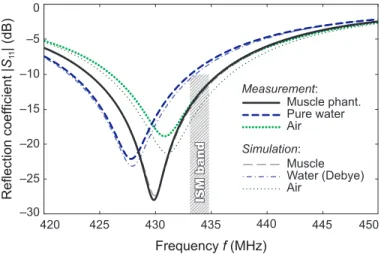
permittivity εr. (b) Conductivity σ. –30 –25 –20 –15 –10 –5 0 420 425 430 435 440 445 450 Reflection coef ficient | S11 | (dB) Frequency f (MHz) ISM band Muscle Water (Debye) Air Simulation: Muscle phant. Pure water Air Measurement:
Fig. 9. Measured and computed reflection coefficients |S11| of the proposed
antenna in three media.
phantoms, we used the SPEAG DAK kit with DAK-12 probe [34]. Fig. 8 shows the measured EM properties of the phantom compared to the target ones. Considering the ultra-robust char-acteristics of the antenna (Fig. 3), the achieved EM properties are sufficienctly accurate. The muscle-equivalent phantom and pure water were contained in a 90 mm × 90 mm cylindrical vessel. As unbalanced feeds affect strongly the measurement accuracy of ESAs [35], we used a methodology proposed by Merli et al. [10]. This approach consists in insulating the feed from a liquid phantom by a layer of air. For that, we surrounded the feeding cable by an airtight 10-mm polyamide tube. Then, we used the Agilent PNA-X VNA to characterize the reflection coefficient of the antenna in different media. As the VNA was calibrated in the reference plane of the SMA connector, the cable influence on impedance was deembedded during postprocessing in CST Design Studio. Fig. 9 shows the reflection coefficients |S11| of the
fab-ricated antenna prototype as measured in muscle-equivalent phantom, air, and pure water. The results in phantom and pure water are in excellent agreement with the simulations. A 2.5-dB difference for |S11| in air can be attributed to the fact that
the antenna couples more to the cable in this configuration (the technique that we used allows us decoupling the antenna only in high-permittivity media).
1 2 3 4 5 6 7 8 9 10 11 12 13 14 15 16 17 18 19 20 21 22 23 24 25 26 27 28 29 30 31 32 33 34 35 36 37 38 39 40 41 42 43 44 45 46 47 48 49 50 51 52 53 54 55 56 57 58 59
V. CONCLUSION
We proposed a biotelemetry capsule platform that can be used for arbitrary in-body applications independently of surrounding tissue. Ultra-robust impedance characteristics of the antenna were achieved for the first time. The antenna is integrated into the PCB of the device along with a sensor (thermocouple), a microcontroller (Si 10XX family), and a power source (button-cell batteries, Fig. 7d). The antenna and the PCB were realized within the same technological process. The radiation performance of the antenna is comparable with counterparts [36]; however, it is less efficient than the hypothetical robust antennas using ceramic materials with εr≥ 10. The proposed antenna gives a sufficient transmission
range of about 2–3 m surrounding a human body when ingested (using a commercially-available chip antenna with G = −3 dBi integrated into the off-body receiver).
Implementation of such biotelemetry capsule (e.g. BodyCap e-Celsuis [8]) can be used, for instance, as an ingestible for humans and as an implantable for a wide range of animals: from rodents to cattle. Roussey et al. [37] reported an in-tracorporal temperature telemetry using a realization of the proposed technology. The proposed design (both in planar and conformal realizations) can find its application in other fields where high robustness to environment is essential.
ACKNOWLEDGMENT
The authors thank Fabrice Verjus as well as Pierre-Alexandre Chapon and Estelle Blond from BodyCap for their support and fruitful discussions.
REFERENCES
[1] A. Kiourti and K. S. Nikita, “A review of in-body biotelemetry devices: implantables, ingestibles, and injectables,” IEEE Trans. Biomed. Eng., vol. 64, no. 7, pp. 1422–1430, Jul. 2017.
[2] A. K. RamRakhyani, S. Mirabbasi, and M. Chiao, “Design and opti-mization of resonance-based efficient wireless power delivery systems for biomedical implants,” IEEE Trans. Biomed. Circuits Syst., vol. 5, no. 1, pp. 48–63, Feb. 2011.
[3] S. Bakogianni and S. Koulouridis, “On the design of miniature MedRa-dio implantable antennas,” IEEE Trans. Antennas Propag., vol. 65, no. 7, pp. 3447–3455, Jul. 2017.
[4] A. S. Y. Poon, “Miniaturized Biomedical Implantable Devices,” in Implantable Bioelectronics, Weinheim, Germany: Wiley-VCH, 2014, pp. 45–64.
[5] L. Xu, M. Q.-H. Meng, and Y. Chan, “Effects of dielectric parameters of human body on radiation characteristics of ingestible wireless device at operating frequency of 430 MHz,” IEEE Trans. Biomed. Eng., vol. 56, no. 8, pp. 2083–2094, Aug. 2009.
[6] D. Nikolayev, M. Zhadobov, P. Karban, and R. Sauleau, “Electromag-netic radiation efficiency of body-implanted devices,” Phys. Rev. Appl., vol. 9, no. 2, pp. 024033, Feb. 2018.
[7] S. Gabriel, R. W. Lau, and C. Gabriel, “The dielectric properties of biological tissues: II. Measurements in the frequency range 10 Hz to 20 GHz,” Phys. Med. Biol., vol. 41, pp. 2251–2269, Nov. 1996. [8] BodyCap Medical. e-Celsius. Accessed: Feb. 20, 2018. [Online].
Avail-able: http://www.bodycap-medical.com
[9] J. Faerber et al., “In vivo characterization of a wireless telemetry module for a capsule endoscopy system utilizing a conformal antenna,” IEEE Trans. Biomed. Circuits Syst., vol. 12, no. 1, pp. 95–105, Feb. 2017. [10] F. Merli, L. Bolomey, J. Zurcher, G. Corradini, E. Meurville, and
A. K. Skrivervik, “Design, realization and measurements of a miniature antenna for implantable wireless communication systems,” IEEE Trans. Antennas Propag., vol. 59, no. 10, pp. 3544–3555, Oct. 2011.
[11] A. Kiourti, J. R. Costa, C. A. Fernandes, A. G. Santiago, and K. S. Nikita, “Miniature implantable antennas for biomedical telemetry: from simulation to realization,” IEEE Trans. Biomed. Eng., vol. 59, no. 11, pp. 3140–3147, Nov. 2012.
[12] Z. Bao, Y. X. Guo, and R. Mittra, “Single-layer dual-/tri-band inverted-F antennas for conformal capsule type of applications,” IEEE Trans. Antennas Propag., vol. 65, no. 12, pp. 7257–7265, Sep. 2017. [13] M. K. Magill, G. A. Conway, and W. G. Scanlon, “Tissue-independent
implantable antenna for in-body communications at 2.36–2.5 GHz,” IEEE Trans. Antennas Propag., vol. 65, no. 9, pp. 4406–4417, Sep. 2017. [14] D. Nikolayev, M. Zhadobov, L. Le Coq, P. Karban, and R. Sauleau, “Robust ultra-miniature capsule antenna for ingestible and implantable applications,” IEEE Trans. Antennas Propag., vol. 65, no. 11, pp. 6107– 6119, Nov. 2017.
[15] W. G. Scanlon, B. Burns, and N. E. Evans, “Radiowave propagation from a tissue-implanted source at 418 MHz and 916.5 MHz,” IEEE Trans. Biomed. Eng., vol. 47, no. 4, pp. 527–534, Apr. 2000. [16] L. C. Chirwa, P. A. Hammond, S. Roy, and D. R. S. Cumming,
“Electromagnetic radiation from ingested sources in the human intestine between 150 MHz and 1.2 GHz,” IEEE Trans. Biomed. Eng., vol. 50, no. 4, pp. 484–492, Apr. 2003.
[17] International Telecommunication Union. ITU Radio Regulations (article 5), footnotes 5.138, 5.150, and 5.280. Accessed: Feb. 20, 2018. [Online]. Available: https://www.itu.int/net/ITU-R/terrestrial/ faq/index.html#g013
[18] Federal Communications Commission. Medical Device
Radio-communications Service (MedRadio). Accessed: Feb. 20, 2018. [Online].
Available:
https://www.fcc.gov/medical-device-radiocommunications-service-medradio
[19] F. Merli, B. Fuchs, J. R. Mosig, and A. K. Skrivervik, “The effect of insulating layers on the performance of implanted antennas,” IEEE Trans. Antennas Propag., vol. 59, no. 1, pp. 21–31, Jan. 2011. [20] D. Nikolayev, M. Zhadobov, P. Karban, and R. Sauleau, “Increasing the
radiation efficiency and matching stability of in-body capsule antennas,”
in Proc. 10thEur. Conf. on Antennas and Propagation (EuCAP 2016),
Davos, Switzerland, 2016, pp. 1–5.
[21] C. Pfeiffer, “Fundamental efficiency limits for small metallic antennas,” IEEE Trans. Antennas Propag., vol. 65, no. 4, pp. 1642–1650, Apr. 2017. [22] A. Karlsson, “Physical limitations of antennas in a lossy medium,” IEEE Trans. Antennas Propag., vol. 52, no. 8, pp. 2027–2033, Aug. 2004. [23] R. Garg, P. Bhartia, I. Bahl, and A. Ittipiboon, Microstrip Antenna
Design Handbook. Norwood, MA: Artech House, 2001.
[24] M. Sagawa, M. Makimoto, and S. Yamashita, “Geometrical structures and fundamental characteristics of microwave stepped-impedance res-onators,” IEEE Trans. Microw. Theory Tech., vol. 45, no. 7, pp. 1078– 1085, Jul. 1997.
[25] D. M. Pozar, Microwave Engineering, 4thed. Hoboken, NJ: Wiley, 2012.
[26] Y. Mahe, A. Chousseaud, M. Brunet, and B. Froppier, “New flexible medical compact antenna: design and analysis,” Int. J. Antennas Propag., vol. 2012, May 2012, Art. no. 837230.
[27] D. Nikolayev, Z. Kubik, P. Karban, and J. Skala, “Impedance analysis of transmission line cells for EMC applications using Agros2D,” Appl. Math. Comput., vol. 289, pp. 381–387, 2016.
[28] D. Nikolayev, M. Zhadobov, P. Karban, and R. Sauleau, “434 MHz
ISM band antenna for in-body biotelemetry capsules,” in Proc. 11th
Eur. Conf. on Antennas and Propagation (EuCAP 2017), Paris, France, 2017, pp. 1035–1038.
[29] P. A. Chapon, A. Gauthier, J. Bulla, and S. Moussay, “Calibration and performance assessment of a temperature sensor prototype using a 1-point calibration procedure,” Rev. Sci. Instrum., vol. 83, no. 11, p. 114907, Nov. 2012.
[30] Computer Simulation Technology AG. CST Microwave Studio. Ac-cessed: Feb. 20, 2018. [Online]. Available: http://www.cst.com [31] D. Nikolayev, M. Zhadobov, and R. Sauleau, “Impact of tissue
elec-tromagnetic properties on radiation performance of in-body antennas,” IEEE Antenn. Wireless Propag. Lett., vol. 17, no. 8, pp. 1440–1444, Jun. 2018.
[32] D. Sinha and G. A. J. Amaratunga, “Electromagnetic radiation under ex-plicit symmetry breaking,” Phys. Rev. Lett., vol. 114, no. 14, p. 147701, Apr. 2015.
[33] C. A. Balanis, Antenna Theory: Analysis and Design, 4thed. Hoboken,
NJ: John Wiley & Sons, 2016.
[34] Schmid & Partner Engineering AG. Dielectric Assessment Kit. Ac-cessed: Feb. 20, 2018. [Online]. Available: http://www.speag.com/ products/dak/dielectric-measurements
[35] L. Huitema, C. Delaveaud, and R. D’Errico, “Impedance and radiation measurement methodology for ultra miniature antennas,” IEEE Trans. Antennas Propag., vol. 62, no. 7, pp. 3463–3473, Jul. 2014.
1 2 3 4 5 6 7 8 9 10 11 12 13 14 15 16 17 18 19 20 21 22 23 24 25 26 27 28 29 30 31 32 33 34 35 36 37 38 39 40 41 42 43 44 45 46 47 48 49 50 51 52 53 54 55 56 57 58 59
8 IEEE TRANSACTIONS ON BIOMEDICAL CIRCUITS AND SYSTEMS, VOL. PP, NO. X
[36] D. Nikolayev, M. Zhadobov, P. Karban, and R. Sauleau, “Conformal antennas for miniature in-body devices: the quest to improve radiation performance,” Radio Sci. Bull., vol. 2017, no. 363, pp. 52–64, Dec. 2017. [37] G. Roussey, M. Gruet, F. Vercruyssen, J. Louis, J.-M. Vallier, and T. Bernard, “Interactions between perceived exertion and thermal percep-tion in the heat in endurance athletes,” J. Therm. Biol., vol. 76, pp. 68–76, Aug. 2018.
Denys Nikolayev (S’14–M’17) received the B.S. (cum laude) and M.S. (cum laude) degrees in elec-tronics and telecommunications from Lviv Poly-technic National University, Lviv, Ukraine, in 2008, and the joint Ph.D. degrees in electronics from the Institute of Electronics and Telecommunication of Rennes (IETR), France and in electrical engineering from the University of West Bohemia in Pilsen, Czechia in 2017.
His research interests include antennas and prop-agation for body-centric networks, neural interfaces, bioelectromagnetics, and numerical methods in electromagnetics. He authored one book chapter, eight journal papers, 16 publications in international conference proceedings, and holds three patents.
Dr. Nikolayev is a member of the Institute of Electrical and Electronics En-gineers (IEEE), the Bioelectromagnetics Society (BEMS), and the European Bioelectromagnetics Association (EBEA). He was awarded by the Foundation of Rennes 1 for his Ph.D. and was a laureate of the Eiffel Excellence Doctoral Grant (2015/2016). He received the Best Paper Award at the URSI–France 2017 Workshop and the Poster Award at the BioEM’2015.
Maxim Zhadobov (S’05–M’07–SM’15) received the M.S. degree in electromagnetics from the Univer-sity of Nizhny Novgorod, Nizhny Novgorod, Russia, in 2003, and the Ph.D. and Habilitation `a Diriger des Recherches (HDR) degrees from the Institute of Electronics and Telecommunications of Rennes (IETR), University of Rennes 1, Rennes, France, in 2006 and 2016, respectively.
He was a Post-Doctoral Researcher with the Center for Biomedical Physics, Temple University, Philadelphia, PA, USA, until 2008, and then joined the French National Center for Scientific Research (CNRS). He is currently the principal investigator in biomedical electromagnetics with the IETR/CNRS and head of the WAVES team of the IETR. He co-authored five book chapters and over 54 research papers in peer-reviewed international journals. He has been involved in over 20 research projects at the National and European levels. His current scientific interests and research activities are in the field of innovative biomedical applications of electromagnetic fields and associated technologies.
Dr. Zhadobov was a session organizer and/or a technical committee member at several international conferences, including IEEE iWEM 2017, BodyNets 2016, MobiHealth (since 2015), IMWS-Bio 2014, and PIERS 2013. Since 2017, he has been Engineering/Physical Sciences Chair of the EBEA Council. He was awarded by the CNRS Medal in 2018, and received EBEA Award for Excellence in Bioelectromagnetics 2015 and the Brittany’s Young Scientist Award 2010. Since 2010, Ph.D. students he supervised received seven national scientific awards and four awards from the Bioelectromagnetics and the IEEE Antennas and Propagation Societies.
Ronan Sauleau (M’04–SM’06–F’18) graduated in electrical engineering and radio communications from the Institut National des Sciences Appliqu´ees, Rennes, France, in 1995. He received the Agr´egation degree from the Ecole Normale Sup´erieure de Cachan, France, in 1996, and the Doctoral degree in signal processing and telecommunications and the “Habilitation `a Diriger des Recherches” degree, both from the University of Rennes 1, France, in 1999 and 2005, respectively.
He was an Assistant Professor and Associate Pro-fessor at the University of Rennes 1, between September 2000 and November 2005, and between December 2005 and October 2009, respectively. He has been appointed as a full Professor in the same University since November 2009. His current research fields are numerical modeling (mainly FDTD), millimeter-wave printed and reconfigurable (MEMS) antennas, substrate integrated waveguide antennas, lens-based focusing devices, periodic and non-periodic structures (electromagnetic bandgap materials, metamaterials, reflectarrays, and transmitarrays) and biological effects of millimeter waves. He has been involved in more than 60 research projects at the national and European levels and has co-supervised 23 post-doctoral fellows, 44 PhD students and 50 master students.
He has received 15 patents and is the author or coauthor of more than 215 journal papers and 470 publications in international conferences and workshops. He has shared the responsibility of the research activities on antennas at IETR in 2010 and 2011. He was co-director of the research Department ‘Antenna and Microwave Devices’ at IETR and deputy director of IETR between 2012 and 2016. He is now director of IETR. Prof. Sauleau received the 2004 ISAP Conference Young Researcher Scientist Fellowship (Japan) and the first Young Researcher Prize in Brittany, France, in 2001 for his research work on gain-enhanced Fabry–Perot antennas. In September 2007, he was elevated to Junior member of the “Institut Universitaire de France”. He was awarded the Bronze medal by CNRS in 2008. He was the co-recipient of several international conference awards with some of his students (Int. Sch. of BioEM 2005, BEMS’2006, MRRS’2008, E-MRS’2011, BEMS’2011, IMS’2012, Antem’2012, BioEM’2015). He served as a guest editor for the IEEE Antennas Propogat. Special Issue on “Antennas and Propagation at mm and sub mm waves”. He served as a national delegate for COST VISTA. Since 2013 he is national delegate for EurAAP, and is a member of the board of directors of EurAAP. 1 2 3 4 5 6 7 8 9 10 11 12 13 14 15 16 17 18 19 20 21 22 23 24 25 26 27 28 29 30 31 32 33 34 35 36 37 38 39 40 41 42 43 44 45 46 47 48 49 50 51 52 53 54 55 56 57 58 59