High-coherence dual-comb interferometry with
free-running lasers
Thèse
Nicolas Bourbeau Hébert
Doctorat en génie électrique
Philosophiæ doctor (Ph. D.)
High-coherence dual-comb interferometry with
free-running lasers
Thèse
Nicolas Bourbeau Hébert
Sous la direction de:
Résumé
La spectroscopie double-peigne est une technique qui consiste à faire interférer deux peignes de fréquences laser légèrement désynchronisés ayant sondé un échantillon afin de retrouver sa signature spectrale avec une haute résolution et à grande vitesse. Cependant, elle requiert deux lasers qui sont mutuellement cohérents, une contrainte qui est habituellement satisfaite par stabilisation active au prix d’une plus grande complexité matérielle. Cette thèse aborde ce problème en présentant des solutions qui permettent l’utilisation de peignes en opération libre, simplifiant ainsi la technique du double-peigne.
On démontre d’abord une plateforme laser compacte capable de générer une paire de peignes de fréquences qui sont affectés de manière similaire par les perturbations environnementales. Elle est basée sur une puce de verre dopée à l’erbium contenant plusieurs guides d’ondes inscrits par laser et séparés de quelques centaines de microns. Deux guides adjacents sont pompés simultanément et opérés en régime de synchronisation modale à ∼ 1 GHz dans la bande de 1.5 µm pour fournir une paire de peignes corrélés. Le bruit de fréquence en opération libre de cette source est ensuite caractérisé et on estime un temps de cohérence mutuelle qui dépasse le temps de mesure requis pour obtenir un spectre à haute résolution. Ceci est rendu possible grâce à l’utilisation de lasers qui sont intrinsèquement peu bruités, à l’intégration mécanique de la source, et à l’utilisation d’une grande différence entre les cadences des peignes.
On présente aussi deux algorithmes de correction qui, lorsque combinés avec notre source double-peigne, permettent d’étendre artificiellement son temps de cohérence afin d’augmenter le temps de moyennage utile sans sacrifier la résolution spectrale. Ces algorithmes estiment et compensent la phase et le temps d’arrivée des interférogrammes mesurés, et ce sans recourir à aucune mesure externe des fluctuations des peignes. Ils sont d’abord décrits en détail puis leurs limites sont déterminées de façon quantitative à partir des paramètres des peignes et de leur bruit de fréquence relatif, où une grande différence entre les cadences apparaît comme étant la clé d’une correction réussie.
Finalement, les performances du spectromètre double-peigne assisté par la correction logi-cielle sont démontrées en mesurant le spectre de transmission de l’acétylène et du cyanure d’hydrogène avec un échantillonnage spectral de ∼1 GHz. La qualité des mesures est validée par comparaison avec des spectres simulés à partir de données connues.
Abstract
Dual-comb spectroscopy is a technique where two slightly detuned laser frequency combs are interfered together after probing a sample under study in order to retrieve its spectral signature with a high resolution and at high speed. However, it requires two lasers that are mutually coherent, a constraint that is most often satisfied by active stabilization at the cost of an increased hardware complexity. This thesis tackles this issue by presenting solutions that allow the use of free-running combs, thus simplifying the dual-comb technique.
First, we demonstrate a compact laser platform able to generate a pair of frequency combs that are similarly affected by environmental perturbations. It is based on an erbium-doped glass chip containing a number of ultrafast-laser-inscribed waveguides separated by a few hundred microns. Two adjacent waveguides are pumped simultaneously and passively mode-locked at ∼1 GHz in the 1.5 µm band to deliver a pair of correlated frequency combs. The free-running frequency noise of this source is characterized thoroughly and its mutual coherence time is found to exceed the measurement time required to retrieve a high-resolution spectrum. This is made possible by the use of intrinsically low-noise waveguide lasers, by the dual-comb source’s mechanical integration, and by the use of a large repetition rate difference between the combs. We also present two correction algorithms that, when combined with our dual-comb source, allow to artificially extend its coherence time in order to increase the useful averaging time without sacrificing the spectral resolution. These algorithms work by estimating and compen-sating the phase and timing of the measured interferograms without relying on any external measurement of the combs’ fluctuations. They are first described in detail and their limita-tions are determined quantitatively in terms of the combs’ parameters and relative frequency noise, where a large repetition rate difference appears to be the key to a successful correction. Finally, the performance of the dual-comb spectrometer assisted by a software correction is demonstrated by measuring the transmission spectrum of acetylene and hydrogen cyanide with a spectral sampling of ∼1 GHz. The quality of the measurements is validated by comparison to spectra simulated from known data.
Contents
Résumé ii
Abstract iii
Contents iv
List of Tables vi
List of Figures vii
List of Abbreviations and Acronyms x
Remerciements xi
Foreword xii
Introduction 1
1 Dual-comb laser source 13
1.1 The waveguide chip laser. . . 13
1.2 First dual-comb source . . . 16
1.3 Coupling light in and out of the waveguides using graded-index fibre . . . . 22
1.4 Improved and packaged dual-comb source . . . 28
2 Noise and coherence analysis 35 2.1 Free-running frequency noise . . . 35
2.2 Origin of the white frequency noise floor . . . 45
2.3 Implications in dual-comb spectroscopy . . . 50
3 Correction algorithms 57 3.1 Algorithm based on the cross-correlation function . . . 57
3.2 Algorithm based on the cross-ambiguity function . . . 66
3.3 Limitations imposed by the unwrapping operation . . . 72
3.4 Equivalent resolution loss in case of unwrap errors . . . 81
3.5 Validation . . . 83
4 Spectroscopy 88 4.1 Spectral line profiles . . . 88
4.3 Hydrogen cyanide. . . 94
Conclusion 100
A Linear estimators and their variances 102
A.1 Cross-correlation method . . . 102 A.2 Cross-ambiguity method . . . 103
B Covariance between the two differential phase estimators 107
B.1 Case of the cumulative sum . . . 107 B.2 Case of the trapezoidal sum . . . 108
C Common transfer functions 110
C.1 Delayed difference . . . 110 C.2 Delayed sum . . . 110 C.3 Phase to frequency conversion . . . 111
List of Tables
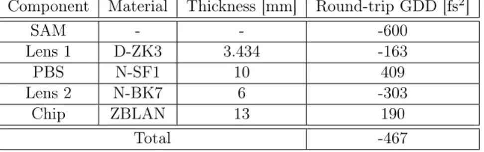
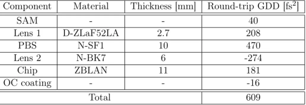
1.1 Round-trip GDD at 1555 nm induced by each component. . . 21 1.2 Round-trip GDD at 1535 nm induced by each component. . . 33 2.1 Parameters of each dual-comb system. . . 45 2.2 Estimated noise levels for comparison with the measured noise floor at 10 Hz2/Hz. 49 4.1 Fit parameters for the acetylene spectrum. . . 94 4.2 Fitted and reference Lorentzian half widths γifor the hydrogen cyanide spectrum. 98
List of Figures
1 Spectral representation of dual-comb spectroscopy. . . 4 2 Temporal representation of dual-comb spectroscopy. . . 5 3 Spectral representation of dual-comb spectroscopy in the presence of frequency
noise. . . 6 4 Different lock points used to stabilize the two degrees of freedom of an optical
frequency comb. The lock points are identified by the modes in red. . . 8 1.1 Section view of a double-ring depressed-cladding waveguide formed by ULI and
three-dimensional view of three waveguides written in a ZBLAN chip. Several overlapping rods of reduced refractive index are written along the chip’s length to form ring-shaped claddings. A microscope image of a typical waveguide is
also shown. . . 15 1.2 Energy level diagram of Er, Yb, Ce tri-doped ZBLAN. The most important
transitions are shown, including the pump absorption (blue), signal emission (red), Yb to Er energy transfers (yellow), Er to Ce energy transfers (green),
and other possible radiative and non-radiative decaying paths (grey). . . 16 1.3 a) Microscope image of two single-mode fibres held together along their length
and sandwiched between two glass slides used to simultaneously inject pump light in two waveguides. b) End view of the same two fibres. c) Pump beam
profiles after propagation through the waveguides. . . 17 1.4 Schematic of the dual-comb laser source. Two mode-locked lasers are generated
using a pair of parallel waveguides written in an Er-doped ZBLAN chip and a
common SAM. LD: laser diode, ISO: isolator. . . 18 1.5 a) Power spectrum of each mode-locked laser constituting the dual-comb source
measured with a resolution bandwidth of 0.2 nm (0.03 nm for the inset). b)
Coherently averaged IGM obtained when beating both lasers on a fast photodiode. 20 1.6 Bidirectional mode field adapter made with a short section of GIF fusion spliced
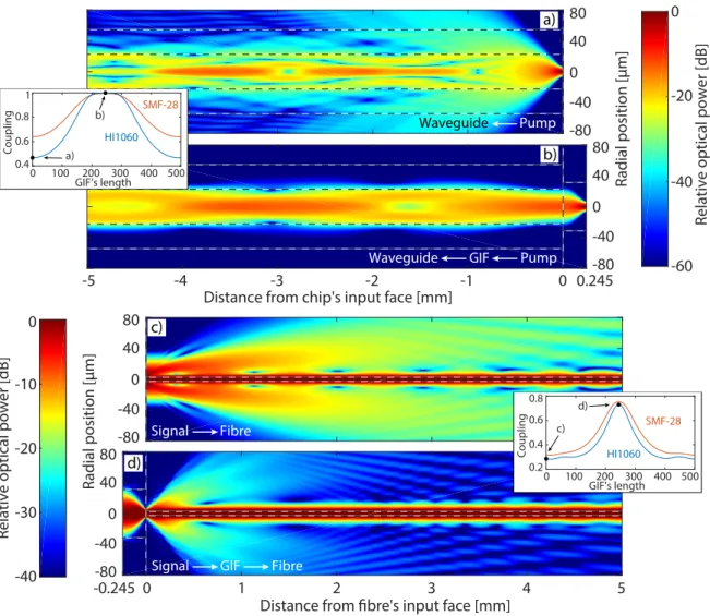
to an SMF. An OC coating can also be deposited on the fibre’s end. . . 23 1.7 a) Propagation of pump light at 976 nm (from right to left, as in Fig. 1.6)
from the output of a fibre through a depressed cladding waveguide a) without using any GIF and b) using a 245 µm section of GIF as a mode field adapter. Propagation of signal light at 1550 nm (from left to right) from the output of a waveguide through a fibre c) without using any GIF and d) using a 245 µm section of GIF as a mode field adapter. The images show the optical power distribution in a radial slice of the beam and the insets show the coupling
efficiency as a function of the GIF’s length. . . 25 1.8 a) Geometry of the non-zero cleave angle problem. b) Effect of the cleave angle
1.9 Schematic of the improved dual-comb source using GIF mode field adapters.
LD: laser diode, ISO: isolator. . . 29
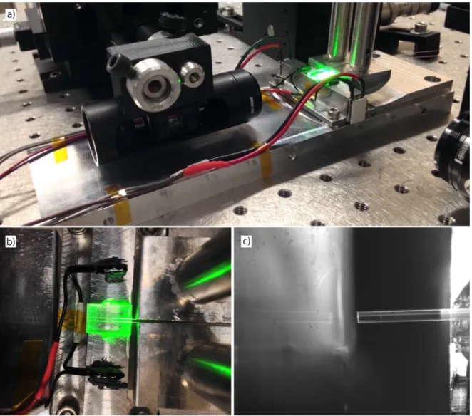
1.10 a) Dual-comb source during alignment on the custom-made aluminum mount. b) Top view of the chip with two fibres aligned to adjacent waveguides. c) Magnified view of a fibre (right) approaching toward the end face of the chip (left). . . 30
1.11 Packaged dual-comb source with components secured on an aluminum mount using glass rods and epoxy. . . 31
1.12 a) Power spectrum of each mode-locked laser constituting the second dual-comb source measured with a resolution bandwidth of 0.02 nm. b) Intensity autocorrelation of each laser c) Averaged IGM. . . 32
2.1 Measurement setup for the characterization of the combs’ relative frequency noise. PC: polarization controller, D: balanced photodetector, ADC: analog-to-digital converter. . . 36
2.2 Phase noise of a mode from each comb relative to the CW laser and relative phase noise between the two combs observed on time scales of a) 1 ms and b) 100 ms. . . 38
2.3 Frequency noise PSD of a mode from each comb relative to the CW laser (blue and yellow) and relative frequency noise PSD between the two combs (red). The CW laser’s frequency noise PSD measured against a MZI is also shown (black). The fitted curve (green) is obtained using Eq. (2.6), the dashed line is the β separation line, and the dotted line shows the measurement noise limit. . 39
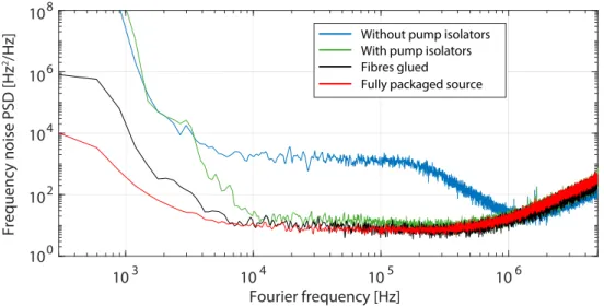
2.4 Relative frequency noise PSDs measured while assembling the source. . . 42
2.5 Relative frequency noise PSDs measured with pumps driven at 1.45 A and 1.3 A. 42 2.6 a) Absolute and relative frequency noise PSDs measured while actively perturb-ing the combs with knockperturb-ing and hand clappperturb-ing. b) CMRR of environmental perturbations estimated from the difference between the absolute and relative frequency noise PSDs. . . 43
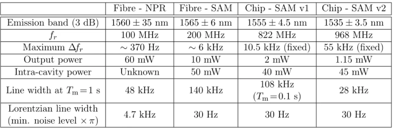
2.7 Relative frequency noise PSD of various dual-comb systems operating in free-running mode. . . 45
2.8 RIN PSD of each comb as well as of each pump diode. . . 49
2.9 Contributions of the observation window and frequency noise to the RF line width. . . 51
2.10 Dual-comb spectra generated from series of consecutive IGMs with integration times ranging between 0.1 ms and 10 s. Each spectrum is shown with a different offset for display purposes.. . . 53
2.11 a) A few coherence functions and coherence times estimated with different mea-surement times. b) Coherence time as a function of the meamea-surement time, where the duration of a single IGM is equivalent to 1/(55 kHz) = 18 µs. . . 55
3.1 Measured signal V (t) and its associated spectrum. . . 58
3.2 Demodulated signal Vd(t) and its associated spectrum. . . 59
3.3 Cross-correlation function ρ1(τ ) computed with v0(t) and v1(t). . . 60
3.4 Estimated data points (τk, φk) and (τk, 2πk) along with their interpolated phase signals ˜φ(t) and ˜φr(t). . . 61
3.5 Phase corrected signal Vp(t) and its associated spectrum.. . . 63
3.7 Flowchart of the correction algorithm based on the cross-correlation function. . 65 3.8 Demodulated signal Vd(t) with stronger phase excursions and its associated
spectrum. . . 66 3.9 Modulus of the cross-ambiguity function |χ1(τ, f )| computed with v0(t) and v1(t). 67 3.10 Modulus of the cross-ambiguity function |χ1(τ, f )| computed with v0(t) and
v1(t) modified with a linear frequency chirp of 40 Hz/s. . . 68 3.11 Estimated data (τk, fk, φk) and (τk, 2πk) along with the interpolated phase
sig-nals ˜φ(t) and ˜φr(t), where the fk values help the phase unwrapping operation
by providing the local phase slopes. . . 69 3.12 Flowchart of the correction algorithm based on the cross-ambiguity function. . 71 3.13 Frequency response of filters applied to Sf(ξ) to calculate Var[∆ ˆφk] for the case
of Gaussian-shaped IGMs with ∆f−1
r = 100T . . . 74 3.14 Frequency response of filters applied to Sf(ξ) to calculate Var[∆ ˆφk− ∆ˆΦk] for
the case of Gaussian-shaped IGMs with ∆f−1
r = 100T using a) the cumulative
sum and b) the trapezoidal sum. . . 79 3.15 a) Cosines at frequencies n∆fr, with n integer, representing the carrier of
cor-rected IGMs having n missing or extra phase cycles. b) Apodization windows obtained by assuming normally (Gaussian) distributed phase values with
dif-ferent standard deviations s.. . . 82 3.16 Measurement setup for the validation of the correction methods. PC:
polariza-tion controller, D: balanced photodetector, ADC: analog-to-digital converter. . 83 3.17 a) Estimated repetition phase ˜φr(t) without the mean phase slope 2π∆frt. b)
Estimated phase ˜φ(t) and true phase φ(t) measured through a CW laser. c)
Difference between ˜φ(t) and φ(t). . . 84 3.18 Dual-comb spectrum at different stages of the cross-correlation-based
correc-tion. Green: raw spectrum. Red: after phase correccorrec-tion. Blue: after resampling
correction. . . 84 3.19 Modulus of the cross-ambiguity function calculated with the 0thand 100thIGMs
affected by chirp. . . 86 3.20 a) Estimated repetition phase ˜φr(t) without the mean phase slope 2π∆frt. b)
Estimated phase ˜φ(t) and true phase φ(t) measured through a CW laser. c)
Difference between ˜φ(t) and φ(t). . . 87 3.21 Dual-comb spectrum at different stages of the cross-ambiguity-based correction.
Green: raw spectrum. Red: after phase correction. Blue: after resampling
correction. . . 87 4.1 Measurement setup for the spectroscopy of acetylene. PC: polarization
con-troller, D: balanced photodetector, ADC: analog-to-digital converter. . . 90 4.2 Transmission spectrum of acetylene for different measurement times. . . 91 4.3 SNR as a function of the measurement time.. . . 92 4.4 Transmission spectrum of acetylene in magnitude and phase fitted with Eq. (4.5). 94 4.5 Measurement setup for the spectroscopy of hydrogen cyanide. PC: polarization
controller, D: photodetector, ADC: analog-to-digital converter. . . 95 4.6 Transmittance spectrum of hydrogen cyanide for different measurement times. . 96 4.7 Transmittance spectrum of hydrogen cyanide fitted with Eq. (4.6). . . 98
List of Abbreviations and Acronyms
AC Alternating Current
AR Anti-Reflection
CEO Carrier-Envelope Offset
CMRR Common-Mode Rejection Ratio
CW Continuous-Wave
DC Direct Current
GDD Group Delay Dispersion
GIF Graded-Index Fibre
IGM Interferogram
MZI Mach-Zehnder Interferometer
NIST National Institute of Standards and Technology NPR Nonlinear Polarization Rotation
OC Output Coupler
PBS Polarization Beam Splitter
PSD Power Spectral Density
RBW Resolution Bandwidth
RIN Relative Intensity Noise
RF Radio Frequency
SAM Saturable Absorber Mirror
SMF Single-Mode Fibre
SNR Signal-to-Noise Ratio
ULI Ultrafast Laser Inscription WDM Wavelength-Division Multiplexer
Remerciements
Je tiens d’abord à remercier sincèrement mon directeur de recherche, Jérôme Genest, de m’avoir guidé et supporté tout au long de mes travaux. Sa rigueur, sa disponibilité et la proximité qu’il entretient avec ses étudiants font en sorte que de travailler avec lui est un réel plaisir. Je lui suis infiniment reconnaissant pour toutes les opportunités qu’il a pu m’offrir, particulièrement pour les expériences extraordinaires en Australie, qui ont eu un immense impact positif dans ma vie autant sur le plan professionnel que personnel.
I would also like to express my gratitude to David Lancaster for his valuable collaboration during this project and for providing us with chips. Without him, this project would simply not have been possible.
J’aimerais remercier mes anciens et actuels collègues Vincent, Jean-Daniel, Alex, Khaoula, Philippe, Steeve, Hugo, Connor et Carlos, pour tous les moments amusants et les discussions stimulantes qui ont rendu mon passage ici plus qu’agréable. Je tiens à dire un merci particulier à Vincent, un compagnon de travail et de voyage sur qui j’ai pu compter tout au long de mes études universitaires.
Merci à ma famille, et tout spécialement à mes parents, Élise et Sylvain, pour leur soutien et leurs encouragements continuels. Ils ont su me guider tout au long de ma vie et m’ont toujours appuyé dans ce que j’entreprenais. Je leur en suis profondément reconnaissant.
I also wish to thank my love, friend, and partner, Carly, for making my everyday life happier and for her moral support during the stressful last few months. I cannot thank her enough for being here with me during this adventure even though it meant moving to the other side of the world.
En terminant, je remercie le Conseil de recherches en sciences naturelles et en génie du Canada, le Fonds de recherche du Québec - Nature et technologies, ainsi que Boeing et Telops, pour leur soutien financier.
Foreword
The work presented in this thesis has directly led to the journal publications, conference pre-sentations, and patent applications listed below:
Journal papers
• N. B. Hébert, J. Genest, J.-D. Deschênes, H. Bergeron, G. Y. Chen, C. Khurmi, and D. G. Lancaster, "Self-corrected chip-based dual-comb spectrometer," Opt. Express, 25(7), 8168-8179 (2017).
• N. B. Hébert, D. G. Lancaster, V. Michaud-Belleau, G. Y. Chen, and J. Genest, "Highly coherent free-running dual-comb chip platform," Opt. Lett. 43(8), 1814-1817 (2018). • N. B. Hébert, V. Michaud-Belleau, J.-D. Deschênes, and J. Genest, "Self-correction limits
in dual-comb interferometry," IEEE J. Quantum Electron. 55(4), 1-11 (2019).
Conference presentations
• N. B. Hébert, J.-D. Deschênes, H. Bergeron, G. Y. Chen, C. Khurmi, D. G. Lancaster, and J. Genest, “Transform-limited dual-comb spectroscopy using free-running waveguide lasers,” in “CLEO: Science and Innovations,” (Optical Society of America, 2017), pp. SM4D–1. • N. B. Hébert, D. G. Lancaster, G. Y. Chen, and J. Genest, “Low-noise dual-comb platform
based on mode-locked lasers in a multi-waveguide chip,” in “CLEO: Science and Innovations,” (Optical Society of America, 2018), pp. SW4L–5.
Patent applications
• N. B. Hébert, J. Genest, J.-D. Deschênes, and D. Lancaster, "Methods for performing dual-comb interferometry," PCT patent application WO2018102915A1 (December 7, 2016). • D. Lancaster, N. B. Hébert, C. Khurmi, and J. Genest, "An optical plural-comb
gen-erator, a method of generating an optical plural comb, and a plurality of mode locked lasers that are mechanically coupled and optically independent," PCT patent application WO2018152594A1 (February 27, 2017).
Introduction
Frequency combs and dual-comb spectroscopy
Optical frequency combs [1,2] are light sources able to generate a large number of equidistant optical frequencies, or discrete modes, having a deterministic phase relationship. As a result of these properties, frequency combs are at the origin of many of the recent advances in the field of optical metrology. Among other things, they have been found to be invaluable tools for optical clockworks [3], distance measurements [4], time and frequency transfer [5], and for the calibration of other instruments such as astronomical spectrographs [6]. Spectroscopy is also an area that has directly benefited from these sources. Their narrow and finely spaced emission lines allow to probe the spectral signature of a sample over a large bandwidth and with an unparalleled resolution, sometimes surpassing the performance of traditional spectrometers by orders of magnitude [7–14].
In the time domain, these lasers produce a signal with a periodic envelope where the repetition period is the inverse of the frequency spacing between the modes. This envelope often takes the form of short pulses with combs based on mode-locked lasers [15], but other generation mechanisms, such as those relying on the modulation of a continuous-wave (CW) laser [16], can lead to any envelope shape. Mathematically, the electric field E(t) of an ideal frequency comb can simply be written as a sum of complex exponentials:
E(t) =X m
Amexp[j(2πνmt + θm)], (1)
where Am, νm and θm are the amplitude, frequency and phase of the mth comb mode. Ad-ditionally, the frequency of each mode can be decomposed in terms of the repetition rate fr, which sets the frequency spacing, and of the frequency of a reference mode ν0 that is not necessarily an integer multiple of the spacing such that:
νm = ν0+ mfr, (2)
where m is the mode index with m = 0 for ν0. Throughout this thesis, the mode numbering is made such that the index m = 0 refers to a comb mode that is within the emission spectrum. However, note that, in the literature, the index 0 sometimes designates the lowest-frequency
mode, even if it is actually never emitted by an optical comb (its amplitude is zero). This virtual mode bears a particular meaning as it describes the rate at which the carrier phase and the envelope of E(t) slip from each other [17], which is necessarily slower than fr. For this reason, it is often referred to as the carrier-envelope offset (CEO) and is associated with the alternative definition νm = fCEO+ m′fr with m′ = 0 for fCEO and m′ 6= m. The presence of this second degree of freedom in the comb’s frequencies is simply the consequence of unequal phase and group velocities inside the laser cavity [17].
In the context of spectroscopy, a frequency comb can effectively interrogate a sample of in-terest at each frequency obeying to Eq. (2), whose transfer function becomes encoded on the comb modes in Am and θm. The resulting spectral sampling is thus equivalent to the comb’s repetition rate fr, which typically ranges from a few tens of MHz to a few GHz for mode-locked frequency combs. The available spectral resolution is in fact much finer than the spectral sampling since the former is determined by the line width of each individual mode, which can be orders of magnitude smaller than their spacing. However, extracting the infor-mation encoded on the comb without any loss of resolution can be a challenging task given the relatively small modal spacing. For example, grating-based spectrum analyzers can barely, if not at all, resolve the modes of typical frequency combs. More advanced readout techniques making use of cascaded dispersive elements must then be employed, including Vernier cavities [10, 11] and virtually imaged phased arrays [12, 13]. Interestingly, if these instruments are able to distinguish individual modes well enough, their instrumental broadening or instru-mental line shape becomes irrelevant and the resolution remains limited by the comb’s line width. Such comb-limited resolution can also be reached when analyzing the light through an interferometer whose maximum delay is exactly matched to the inverse of fr [14]. This last technique thus requires scanning a mirror over tens of centimetres and sometimes even over a few meters, depending on the comb’s repetition rate.
Alternatively, a readout approach based on heterodyne detection can be used to map each comb mode to radio frequencies (RF). In its simplest form, this task can be accomplished by combining the comb with a CW laser in a fibre coupler or a beam splitter and by mixing their fields on a photodiode [18]. Each comb mode then creates an RF tone whose frequency is equal to the separation between the mode and the CW laser, resulting in an RF spectrum approximately as broad as the optical spectrum and that is usually limited by the detection bandwidth. To reduce the required bandwidth, we could instead imagine a "multi-heterodyne" readout scheme where a different CW laser is used to convert each comb mode down to a selectable and unique RF frequency. Implementing this exact idea with more than a few modes would be a colossal task, but it suddenly sounds much more accessible if the CW lasers are replaced by a second frequency comb. This technique, where the spectral information encoded on one comb is extracted by heterodyne detection with the aid of a second comb, is commonly referred to as dual-comb spectroscopy [19–32].
In complex representation, two combs interfering on a photodetector produce a voltage of the form: V (t) ∝ [E1(t)E2∗(t)] ∗ hd(t) ∝ " X m A1mexp[j(2πν1mt + θ1m)] X l A2lexp[−j(2πν2lt + θ2l)] # ∗ hd(t) ∝ " X m X l A1mA2lexp[j(2π(ν1m− ν2l)t + θ1m− θ2l)] # ∗ hd(t), (3)
where we neglected the terms that dot not arise from the interference. The indices 1 and 2 refer to the first and second comb, m and l are mode indices with m=l =0 referring to two adjacent modes near the spectra’s centre, hd(t) is the impulse response of the low-pass detection chain, and ∗ denotes both the complex conjugation and the convolution operations. By comparison with Eq. (1), the double sum in the last expression indicates that the interference of two optical combs produces a series of RF combs [33]. If hd(t) is chosen to isolate the lowest-frequency tones below fr/2 generated by pairs of adjacent optical modes where m = l, we obtain a single RF comb whose voltage is:
Vm=l(t) ∝ X
m
A1mA2mexp[j(2π(ν1m− ν2m)t + θ1m− θ2m)]. (4) The amplitude and phase response of a sample interrogated by the first comb at optical frequencies ν1m are encoded in A1m and θ1m, respectively, and appear at RF frequencies ν1m− ν2m. From Eq. (2), these frequencies can be written as:
fm= ν1m− ν2m = f0+ m∆fr,
(5)
where the offset f0 = ∆ν0 is the frequency difference between the two central modes and the spacing ∆fr is the repetition rate difference.
Figure 1illustrates the working principle of dual-comb spectroscopy in the frequency domain with ideal combs. A first comb (blue) with repetition rate fris used to interrogate an arbitrary sample whose transfer function is imprinted directly on its modes. The sample could be a molecular gas, as in many of the dual-comb demonstrations referenced before, or any other optical device. A second comb (red) with repetition rate fr+ ∆fr is used as a local oscillator to perform a heterodyne detection of the first comb. When mixed on a photodiode, each pair of optical modes produces an RF tone of strength proportional to the product of their amplitudes and at a frequency equal to their separation. From the figure, it is obvious that the second comb must have a repetition rate close, yet slightly different, to that of the first comb in order to produce RF tones at unique frequencies. The tones arising from pairs of adjacent optical modes form a new RF comb (green) with a frequency spacing ∆fr that also carries the sample’s full-resolution transfer function. The spectral information is thus compressed within a
Optical frequency Radio frequency Comb 1 Comb 2 fr fr + Δfr Δfr RF comb m=0l=0 m=0
Figure 1: Spectral representation of dual-comb spectroscopy.
bandwidth that is ∆fr/frtimes smaller, which is now accessible for analysis with conventional RF equipment. For the optical domain with bandwidth ∆ν to be mapped without ambiguity to the RF domain in an fr/2 bandwidth, the following condition must be satisfied [19]:
∆ν ×∆fr fr < fr 2 =⇒ ∆fr < f2 r 2∆ν. (6)
This condition basically avoids overlapping, or aliasing, between the multiple RF combs de-scribed by Eq. (3) . In Fig. 1, only one optical comb is used to interrogate the sample of interest, which results in an RF comb containing both its amplitude and phase response. However, the sample can also be interrogated by both combs at the same, resulting in an RF spectrum containing only the power response of the sample.
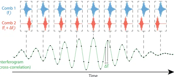
Figure 2 illustrates the working principle of dual-comb spectroscopy in the time domain in-stead. A first pulse train (blue) modified by the sample’s impulse response is mixed on a photodiode with a second pulse train (red) having a detuned repetition rate. For each pair of optical pulses, the detector outputs a signal proportional to the overlap between their elec-tric fields. With ideal combs, the delay between pairs of pulses increases linearly by steps of ∆T = 1/fr− 1/(fr+ ∆fr) ≈ ∆fr/fr2 [19], which generates a time-stretched version of the two fields’ cross-correlation (green). After low-pass filtering below fr/2, the resulting interference signal takes the form of a pulse train with a periodic envelope repeating once every 1/∆fr, which is commonly referred to as an interferogram (IGM). Taking the Fourier transform of one or many consecutive IGMs yields the spectrum of interest, as depicted in the bottom panel of Fig. 1. A spectrum with resolution limited by the optical line width is available after the measurement of one full-duration IGM, while subsequent IGMs can be used to perform aver-aging and improve the signal-to-noise ratio (SNR). Therefore, the acquisition speed is limited by the choice of ∆fr, which must in turn satisfy Eq. (6).
Time Comb 1 Comb 2 Interferogram (cross-correlation) (fr) (fr + Δfr) ΔT
Figure 2: Temporal representation of dual-comb spectroscopy.
Dual-comb spectroscopy with imperfect combs
The situation depicted before assumed the use of ideal and perfectly stable frequency combs for which the parameters fr and ν0 were independent of time. In practice, combs are affected by fluctuations of all sorts that can either be of an intrinsic nature (e.g. fundamental quantum noise) or of a technical nature (e.g. mechanical, thermal, and pump noise). In the presence of noise, the optical frequencies in Eq. (2) become:
[νm+ δνm(t)] = [ν0+ δν0(t)] + m[fr+ δfr(t)], (7) where δνm(t), δν0(t) and δfr(t) are additive frequency noise terms. For the comb modes to be properly resolved, δνm(t) should take values that are much smaller than the nominal spacing fr. Fortunately, this condition is easily fulfilled even by a free-running mode-locked laser. In dual-comb spectroscopy, the frequency noise on one optical comb is typically uncorrelated with the noise on the other comb, which also gives rise to a noisy RF comb. The RF frequencies in Eq. (5) thus become:
[fm+ δfm(t)] = [f0+ δf0(t)] + m[∆fr+ δ∆fr(t)], (8) where the noise terms here are √2 times larger than those in Eq. (7) for uncorrelated and statistically identical optical combs (2 times larger in terms of frequency noise power). This time, δfm(t) should take values that are much smaller than the nominal spacing ∆fr to allow resolving the RF comb modes. However, this condition is much more restrictive than the previous one since ∆fris typically orders of magnitude smaller than fr, whereas the amplitudes of δfm(t) and δνm(t) are comparable. Even if optical modes are well resolved, the inability to resolve the RF modes can result in an important loss of resolution since the spectroscopic information that they individually carry becomes mixed with that of their neighbours. Figure 3
Optical frequency Radio frequency Comb 1 Comb 2 fr fr + Δfr Δfr RF comb
Figure 3: Spectral representation of dual-comb spectroscopy in the presence of frequency noise.
illustrates the effect of frequency noise schematically with moderately broadened modes, which results in a distortion of the spectral feature of interest.
As a numeric example of the impact of frequency noise, consider the case of two optical combs with fr = 1 GHz, ∆fr = 1 kHz, and a line width on the order of 1 MHz. The spectral resolution available with these combs is thus 1 MHz, whereas the spectral sampling density is 1 GHz. If the frequency noises on the two combs are uncorrelated, the corresponding RF comb also has a line width on the order of 1 MHz1. However, its spacing of only ∆f
r = 1 kHz means that a single RF mode extends over approximately 1 MHz/1 kHz = 1000 adjacent modes. Once converted back in terms of optical frequencies, this translates into an effective resolution of 1000fr= 1 THz, which is far beyond the available resolution of 1 MHz. Here, the RF line width can be seen as an instrumental broadening factor intrinsic to the dual-comb readout technique that becomes important when the line width is comparable to or larger than ∆fr. We see that a highly stable RF comb is required in order to preserve the resolution made available by the optical combs. Obviously, eliminating the optical noise terms in Eq. (7) for both combs also leads to a stable and narrow line width RF comb. However, the fact that its frequencies fm are derived from the differences ν1m− ν2mmeans that a similar result can be obtained if the fluctuations are identical in both combs, which amounts to eliminating the RF noise terms in Eq. (8) only. In both cases, the optical combs are said to have a high level of mutual coherence or to be mutually coherent. In practice, the level of coherence of a dual-comb system is always finite and can be quantified through its coherence time. This quantity indicates for how long the mutual coherence can be maintained, which in turn indicates how
1
Formally, the line width is closer to 2 × 1 MHz, but the exact full width at half maximum depends on the noise statistics.
many consecutive IGMs can be averaged together without any loss of spectral resolution. Such averaging is almost always required in dual-comb spectroscopy because of the rather low SNR provided by a single IGM. Therefore, systems with long coherence times are also able to generate higher quality spectra. At minimum, the coherence time should be longer than the duration of one complete IGM in order to retrieve a full-resolution spectrum.
Traditional approaches to enforce mutual coherence
Traditionally, the mutual coherence is maintained by actively controlling the combs’ param-eters through phase locks [23–25, 31, 32]. Since a frequency comb has only two degrees of freedom, namely a frequency offset and a frequency spacing, two phase locks are sufficient to control the frequencies of all its modes. Two approaches can be considered in this case: locking both degrees of freedom on both optical combs for absolute frequency stability, or locking both degrees of freedom on the RF comb for relative frequency stability. In theory, any two frequencies describing the comb, including any νm (or fm) and fr (or ∆fr), can be stabilized against references to fully control all degrees of freedom. In practice, phase locks are not perfect because of their finite loop bandwidth and because they rely on estimated parameters that can be corrupted by measurement noise. Therefore, using two frequencies that are far from each other allows to minimize the impact of residual noise and to better define the comb’s frequency axis. Note that locking νm and fr amounts to locking νm and νm+1= νm+ fr , as shown in Fig. 4a), which goes against this principle.
One notable implementation of a fully stabilized dual-comb system is that where all four optical degrees of freedom are actively stabilized against two stable CW lasers [23,24], which yields kHz-level frequency accuracy and resolution or better (limited by the CW lasers). This allows to stabilize two modes from each comb that are far from each other, as shown in Fig. 4b). The two combs are individually mixed with the CW lasers on photodiodes, yielding four heterodyne signals for which the phase must be stabilized. These signals are sent to phase-locked loops that allow stabilizing the system either through direct feedback on comb actuators (cavity stretchers, pump power, etc.) or through feedforward control using external actuators (acousto-optic modulator, electro-optic modulator, etc.). If the absolute emission frequencies of the CW lasers are known, these can also be used to define the combs’ frequency axis. A spectral separation between the CW lasers of a few THz is typically used to perform this kind of stabilization, which is ultimately limited by the combs’ emission bandwidth. The separation between the two lock points can be extended beyond the emission bandwidth up to a few hundred THz if the CEO frequency is used as a lock point [25,32], as shown in Fig. 4c). Although this approach can lead to lesser noise on the optical comb modes, its implementation is also more complicated. As before, an optical mode from each comb is stabilized against a common CW laser. However, the CEO mode is not actually emitted and must be generated
Optical frequency νmνm+1 fr νm νm+k νm fCEO a) b) c)
Figure 4: Different lock points used to stabilize the two degrees of freedom of an optical frequency comb. The lock points are identified by the modes in red.
through more advanced techniques [17]. Typically, the comb’s emission spectrum is broadened by propagation through highly nonlinear fibre until an octave-spanning supercontinuum is obtained. This step often requires dispersion management and amplification before launching in the fibre in order to reach high peak intensities and trigger nonlinear effects. The low-frequency end of the supercontinuum is then low-frequency-doubled in a nonlinear crystal and is compared with the high-frequency end of the supercontinuum through heterodyne detection. Since the doubling operation also doubles the CEO frequency, comparison of doubled light with non-doubled light creates an RF tone at exactly one time the CEO frequency. This procedure is implemented for both combs and the generated CEO signals are either forced to a frequency of 0 or to a predetermined frequency using phase-locked loops. Compared with the previous approach using two CW lasers, this one does pose more important technical challenges and also requires more specialized components.
The techniques presented so far offered absolute frequency stability and kHz-level resolution, which are not required in most molecular spectroscopy experiments. Indeed, the absorption features of interest have widths on the order of GHz or more. Therefore, stabilizing one comb against the other while letting them drift together is usually more than sufficient. This relative stabilization approach effectively cancels the noise on two different modes of the RF comb and requires only two phase-locked loops instead of four [31]. However, as the noise’s bandwidth usually extends beyond the RF mode spacing, CW lasers are still required to isolate the frequency noise on two modes from each optical comb. These four heterodyne signals can be mixed in pairs to produce isolated replicas of the two RF modes of interest, which are then used as feedback signals.
All of these active stabilization approaches can be converted into correction approaches by monitoring the noise signals at the output of the detectors instead of feeding them to actuators. The optical combs are then left free-running and the frequency accuracy and resolution are limited by the free-running optical line width. However, it is still possible to recover the combs’ mutual coherence and produce a narrow line width RF comb by cancelling the observed relative fluctuations, which involves phase shifting the generated IGMs and sampling them on a grid where the delay increments ∆T are constant. These corrections can be done in real time with digital [27] or analog [29] electronics, as well as in post-processing if the noise signals are digitized and recorded [26]. One advantage of these approaches is the fact that they open the door to much higher correction bandwidths as they are not limited by the response time of an actuator.
Regardless of the approach adopted, several components in addition to the two comb sources are required to perform dual-comb spectroscopy. These can include photodiodes, CW lasers, control electronics, digitizers, RF amplifiers, optical amplifiers, and nonlinear fibres, which all contribute to increasing the overall complexity, cost, and volume of the instrument. More importantly, dual-comb spectrometers usually need to be operated by a highly trained person given the large number of parameters that need to be set in order to reach an adequate state of operation. These factors can in part explain why dual-comb spectrometers remain almost exclusively research laboratory tools and have not attracted much commercial interest yet.
New approaches to enforce mutual coherence
More recently, new approaches have been proposed to simplify dual-comb instruments while maintaining a satisfactory level of mutual coherence. The general idea behind these approaches is to design laser sources able to generate two frequency combs from the same platform that are similarly affected by environmental perturbations and that do not require active stabiliza-tion. The physical proximity between the comb sources is expected to allow them to reject common-mode fluctuations, thus allowing to reach a higher level of mutual coherence while free-running compared to combs generated from separate platforms. Obviously, this is only expected to provide improved performance in cases where the frequency noise is dominated by environmental perturbations.
One approach consists in generating two mode-locked combs directly from the same laser cav-ity. This idea is not new in itself as it has been exploited a long time ago in the colliding-pulse mode-locked ring laser [34], which makes use of two synchronized and counter-propagating pulses. However, the dual-comb technique requires desynchronized pulse trains (∆fr 6= 0), which can be more challenging to generate with only one cavity. Since the physical cavity length is necessarily the same for both pulses, their velocities (or round-trip times) must somehow be made different. One way to address this issue is with a bidirectional ring cavity
where the two propagation directions are not reciprocal due to an asymmetric pumping of the gain medium (a spatially asymmetric distribution of the population inversion) [35–37]. In the mode-locked regime, one pulse enters the gain medium through its high-inversion end whereas the other enters through its low-inversion end, which can suffice to produce an in-tensity mismatch between them. Combined with a nonlinear effect, this mismatch translates into different nonlinear phase shifts and different round trip times for the two propagation directions. A similar idea has also been implemented with microresonator combs [38], where two counter-propagating pulses were formed by asymmetrically pumping both directions of a ring microresonator. A second way of producing two desynchronized pulse trains is by using a birefringent element in the cavity, which introduces a velocity difference between the two orthogonal polarizations. Demonstrations have been made with polarization-maintaining fibre lasers [39,40] as well as with a solid-state laser made with a birefringent crystal [41]. Finally, desynchronized pulse trains can be generated at two different central wavelengths by taking advantage of chromatic dispersion [42,43]. In this case, the output spectra must be broadened through a nonlinear amplification step in order to reach a sufficient level of spectral overlap, as required for the heterodyne detection of the combs.
An issue that can arise with the single-cavity approach is that the two pulses can interact nonlinearly with each other as they circulate [43–45]. Indeed, a passively mode-locked laser necessarily includes a nonlinear element (a saturable absorber for example) to favour the generation of pulses, which must behave differently when two pulses hit it at the same time. In fibre lasers, such interactions are also possible throughout the fibre since the fields are usually intense enough to trigger nonlinear effects. The fact that these pulses travel with different average velocities means that they periodically meet each other at every location in the cavity. The rate at which the pulses meet in one particular location is equal to ∆fr, so the parameters of the output pulses (power, shape, etc.) are also expected to change periodically at this rate as a result of their interaction. For the IGM, this translates into distortions occurring at specific delays that depend on the cavity configuration and on the physical location of the nonlinear element relative to the laser output. In turn, these distortions introduce errors on the measured spectrum. To mitigate this effect, some authors have suggested using a common-path cavity with two uncommon short sections to separate the nonlinear elements used by each comb [45,46].
A safer approach to completely avoid this issue consists in designing a laser platform con-taining two separate and optically independent laser cavities, but that are mechanically and thermally coupled. Here, the level of immunity against environmental perturbations is some-what dependent on how close the two laser cavities can be made. However, introducing a non-zero and adjustable repetition rate difference is much easier since the two optical fields are not collinear. Most notably, dual-comb generation has been demonstrated with an optically pumped surface-emitting semiconductor laser for which two distinct regions of the same gain
chip were pumped simultaneously [47,48], as well as with two quantum cascade lasers grown on the same semiconductor wafer [49]. Additionally, microresonator combs generated from two distinct microresonators from the same photonic chip were also demonstrated [50,51]. Although they can be helpful, it is shown in this thesis that these novel passive stabilization approaches will likely never reach the level of mutual coherence offered by traditional stabiliza-tion or correcstabiliza-tion approaches. However, they might be able to reach a level that is sufficient to unlock access to new software correction methods that do not involve any extra hardware. If the remaining noises δfm(t) are small enough relative to the mode spacing ∆fr, it might be possible to estimate them directly from the measured IGMs without the need to compare the optical combs to CW lasers, as is done with traditional approaches. The mutual coherence could then be reconstructed in software by compensating the estimated noises. Such a correc-tion method has been proposed in [52], where a Kalman filter is used to track the evolution of δfm(t) for each mode of the RF comb. Computationally simpler algorithms have also been proposed in [53,54], where only two frequency trackers are required, one for δf0(t) and one for δ∆fr(t). These were demonstrated with IGMs generated with quantum-cascade combs, which have fewer modes than typical mode-locked combs as well as much larger fr and ∆fr. These conditions undoubtedly contributed to the success of these demonstrations, but it is still not clear if the same methods could be applicable to other types of combs.
Goals of this project and methodology
In light of our discussions on the mutual coherence required for dual-comb spectroscopy and on the complexity that it usually involves, we can define a set of goals for this thesis. Principally, we aim to develop a dual-comb spectrometer able to reach the full resolution potential offered by frequency combs with the lowest level of hardware complexity. For that matter, the instru-ment will need to display a high level of mutual coherence and be able to resolve individual comb modes. In order to make it considerably simpler than traditional systems, we will how-ever only allow the use of free-running sources, leaving aside the auxiliary hardware systems that are specifically dedicated to monitor or actively cancel the combs’ fluctuations. These requirements are set with the intention of coming up with a benchtop dual-comb spectrometer that is cheaper, smaller, and simpler than current solutions.
The specific application considered in this project is molecular gas spectroscopy. At atmo-spheric pressure, pressure broadening is usually the dominant factor contributing to the width of the observed absorption lines [55], which are on the order of several GHz. The use of fre-quency combs with a mode spacing fr ≈ 1 GHz thus seems appropriate for this application. Although combs with a smaller spacing would allow a denser sampling of the absorption lines (but not a higher resolution), using a larger spacing offers other advantages. First, it leads to higher spectral SNR values as this quantity is directly proportional to fr [19]. This can be
understood by the fact that, for a given emission bandwidth, the total power is distributed among fewer modes when fr is large. Second, a large fr allows the use of a large ∆fr, which increases with the square of the former according to Eq. (6). In turn, it reduces the acqui-sition time 1/∆fr for a complete IGM, which reduces the minimum duration over which the combs have to be mutually coherent. Multi-GHz-wide absorption lines also makes the use of active stabilization somewhat irrelevant as free-running combs typically have line widths much smaller than the GHz.
The methodology used in this project is outlined below and broken down into chapters. In Chapter 1, we develop a free-running dual-comb laser source that can naturally offer some mutual coherence through the rejection of environmental perturbations. We aim for a repeti-tion rate on the order of 1 GHz and a relatively high ∆fr. We focus on generating frequency combs from a common platform by making use of two mechanically coupled, but optically independent, laser cavities. This choice is motivated by the undesirable nonlinear interaction between pulses that can occur when using a single cavity. The selected platform is based on a mode-locked glass laser whose centrepiece is a doped-glass chip containing multiple adjacent waveguides that can each accommodate a laser cavity.
In Chapter2, we assess the performance of this dual-comb source in terms of noise. Using a CW laser, we quantify the relative frequency noise between the combs as observed on modes near the centre of their emission spectra and we characterize their immunity against environmental perturbations. More importantly, we evaluate the implications of the observed noise in the context of dual-comb spectroscopy, notably by quantifying the mutual coherence time. In Chapter3, we propose ways of artificially extending the mutual coherence time to arbitrarily large values using signal processing only. We describe two algorithms to estimate the relative noise between the combs using only the IGMs that they generate, that is without relying on information obtained by comparing the combs to CW lasers. We then use the estimated noise to correct the measured IGMs and recover their coherence. We show that using a dual-comb source for which the mutual coherence time already exceeds the duration of a single IGM is a critical condition for the success of these algorithms.
In Chapter 4, we demonstrate the capabilities of chip-based dual-comb sources in molecular spectroscopy when used in combination with a correction algorithm. We measure the trans-mission spectrum of acetylene and of hydrogen cyanide and show that the spectral resolution, set by the combs’ repetition rate, is maintained even when averaging thousands of IGMs to in-crease the SNR. We also analyze the measured spectra through fits and compare the retrieved parameters with reference values.
Chapter 1
Dual-comb laser source
This chapter presents two iterations of a dual-comb source developed in the scope of this project. The aim of this source is to generate two detuned optical pulse trains having an intrinsically high level of mutual coherence without relying on any active phase-locking mech-anism. Making sure that each comb output produces a low-noise signal is obviously one way to achieve this goal, but forcing fluctuations to be shared by both outputs can also be sufficient to reach the desired mutual stability. The dual-comb source introduced below is designed with the intention to allow a maximum rejection of environmental noise, including vibrations and thermal fluctuations, so that the resulting dual-comb interference signal remains somewhat immune to external perturbations. The solution adopted is based on the use of two waveguides embedded in the same piece of doped glass, or chip, enabling the operation of two lasers from a common platform. In this chapter, we introduce the geometry and the fabrication of glass chips and waveguides. We also show how we can take advantage of a multi-waveguide chip for the development of a dual-comb source. Finally, we show how to integrate such a source in a compact platform.
1.1
The waveguide chip laser
The waveguide chip laser is based on guiding channels buried under the surface of a short piece of doped glass of around 1 cm in length, which acts as a gain medium. It is a compromise between the fibre laser and the bulk solid-state laser and thus borrows some characteristics from both. Like fibres, these waveguides allow to maintain high intensities along the entire length of the gain medium by confining light to a small area, which is useful for creating a strong population inversion even when using a relatively low-power and single-transverse-mode pump. The guiding structure is also helpful to maintain a good spatial overlap between the pump and signal beams and therefore to maximize the efficiency of the gain medium. On the other hand, the chip geometry, which reminds that of the bulk laser, facilitates the assembly of short cavities and offers low dispersion by minimizing the propagation through glass.
The chips considered here are made of fluoride glass composed of a mixture of ZrF4-BaF2 -LaF3-AlF3-NaF, commonly known under the acronym ZBLAN. This glass has been proven to have a high solubility for rare-earth ions [56] and good transmission in a broad wavelength range that extends from the visible to the mid-infrared [57]. It thus consists of a versatile host medium for the development of rare-earth-doped glass lasers. As a matter of fact, CW lasing has been demonstrated at various wavelengths using such doped ZBLAN chips, including 636 nm with praseodymium [58], 1 µm with ytterbium [59], 1.5 µm with erbium [60], 1.9 µm with thulium [61], as well as 2.1 µm [62] and 2.9 µm [63] with holmium.
Waveguides can be written in ZBLAN chips by ultrafast laser inscription (ULI), a technique that uses an intense and pulsed laser beam to locally change the optical properties of the glass [64–66]. When focussed inside ZBLAN glass, the beam quickly melts a small region of the solid and, as it resolidifies, the bridging bonds between molecules are reorganized differently than in the pristine glass. The net effect is a localized expansion of the material, which also translates into a reduction of the refractive index [64]. In ZBLAN, ULI can thus not be used directly to create waveguide cores. Instead, ring-shaped claddings are written by translating the position of the focus in the material while making sure to leave an unmodified region in the centre. For the chips used in this thesis, the fabrication and the waveguide inscription was performed by Prof. David Lancaster’s group at the University of South Australia. They used a frequency-doubled 1064 nm femtosecond laser with a 5 MHz repetition rate (IMRA DE0210) able to induce a refractive index change in ZBLAN on the order of δn ≈ −0.001 [64]. The beam was focused 300 to 400 µm under the surface of the chip and a number of parallel and slightly overlapping rods of reduced refractive index were written subsequently along the length of the chip so as the form near-circular depressed-cladding waveguides. Several waveguides with core diameters ranging from 30 to 55 µm were written in the same chip, each with two concentric rings of rods to increase the extent of the cladding region. Figure 1.1 shows the geometry of a double-ring depressed-cladding waveguide and its location in the chip.
The relatively large size of these waveguides makes them capable of supporting more than one transverse mode at common near-infrared wavelengths. However, these modes are usually not all perfectly guided. The finite extent of the cladding region in depressed-cladding waveguides leads to so-called "leaky" modes [67]. Unlike guided modes, these leaky modes slowly lose their energy to the surrounding medium as they propagate through the waveguide. This is explained by the fact that, beyond the depressed cladding, the refractive index is the same as in the core. The core and this third region of the waveguide can then exchange energy through the evanescent field found in the cladding. This phenomenon is similar to the one exploited in fibre couplers. For the energy loss per unit length to be significant, the evanescent field’s amplitude has to be appreciable at the outer interface of the depressed cladding. This also means that high-order modes, which extend farther from the centre, tend to lose energy at a quicker rate than the fundamental mode. A large cladding region does reduce energy leakage,
r n
~ 1 cm
ZBLAN glass chip Depressed-cladding waveguide
30-55 μm
~ 350 μm
0.001
Figure 1.1: Section view of a double-ring depressed-cladding waveguide formed by ULI and three-dimensional view of three waveguides written in a ZBLAN chip. Several overlapping rods of reduced refractive index are written along the chip’s length to form ring-shaped claddings. A microscope image of a typical waveguide is also shown.
but using a smaller region can favour single-transverse-mode operation [68]. Although it was not done here, this parameter could be optimized through numerical simulations in order to properly balance these two effects.
The ZBLAN chips used here are doped with 0.5 mol.% of erbium (Er3+) in order to provide gain in the 1.5 µm spectral band. However, due to the short length of these chips, co-dopants are also used to increase the efficiency of the gain medium when pumped at 976 nm. Ytterbium (Yb3+), which has an absorption cross-section 4 times higher than Er at 976 nm, is also added to the glass in a concentration of 2 mol.% to enhance pump absorption without affecting ground state absorption at the signal wavelength [69]. Due to the existence of transitions of similar energies, Yb ions are able to transfer their absorbed pump energy to Er ions via non-radiative processes. Yb thus makes an excellent sensitizer for Er and, in fact, they have been used together extensively in the fabrication of silica fibre lasers and amplifiers [70–72]. Cerium (Ce3+) is also introduced as a co-dopant in a concentration of 5 mol.%1 to reduce excited state absorption. In Er, the pump wavelength does not only connect the ground level to the upper pump level, but also that latter level to another higher energy level. This has the effect of reducing the probability of Er ions to decay to the signal upper level and participate to population inversion. Fortunately, strong Ce co-doping allows a more than 5-fold increase of that probability (up to 95 %) by encouraging this decaying path through non-radiative energy transfers from Er to Ce ions [69, 73]. Figure 1.2 shows the principal transitions at stake in co-doped ZBLAN. Lifetimes and energy transfer coefficients can be found in [69,73].
1
Such strong doping can sometimes lead to the formation of a few small crystals in the glass. Writing several waveguides at different locations in the chip can thus increase the chip yield significantly.
2F 7/2 Yb3+ Er3+ Ce3+ 2F 5/2 4I 15/2 4I 11/2 4I 9/2 4I 13/2 4F 9/2 4S 3/2 4F 7/2 2F 7/2 2F 5/2 976 nm 976 nm 976 nm 1.55 μm Pump absorption Energy transfer from Yb3+ to Er3+ Signal emission Energy transfer from Er3+ to Ce3+
Figure 1.2: Energy level diagram of Er, Yb, Ce tri-doped ZBLAN. The most important transitions are shown, including the pump absorption (blue), signal emission (red), Yb to Er energy transfers (yellow), Er to Ce energy transfers (green), and other possible radiative and non-radiative decaying paths (grey).
These chips can be turned into efficient CW lasers with only two mirrors and a pump source. A resonator can be formed simply by placing a dichroic mirror on one end of the chip and a partially reflective mirror on the other end. Injecting a sufficient amount of pump light at 976 nm in the waveguide through the dichroic mirror starts the laser effect and allows light at 1.5 µm to be collected from the partially reflective mirror.
1.2
First dual-comb source
Near-infrared waveguide lasers already demonstrated their ability to operate in the mode-locked regime some time ago using a range of different configurations [74–81]. More recently, passive mode-locking was specifically demonstrated with an Er-doped ZBLAN chip used in combination with a semiconductor saturable absorber mirror (SAM) [82], reaching an emission bandwidth of 25 nm. In all cases, a single waveguide from these chips was used at a time. The purpose of the additional waveguides, when present, was typically to have backups in case of damaged or faulty waveguides, or to allow the comparison of various waveguide geometries. Yet, the presence of multiple adjacent waveguides in the same chip or gain medium opens the door to a much wider range of possibilities.
In particular, a multi-waveguide chip offers the possibility to operate two mode-locked lasers simultaneously, which makes this platform quite interesting for dual-comb interferometry. The proximity between the two beam paths certainly allows some mechanical and thermal coupling between them while the use of two separate waveguides guarantees the independence between the electric fields. Because of its anticipated ability to reject environmental noise, the multi-waveguide chip thus stands out as a good candidate for the development of a dual-comb source with high mutual coherence. Additionally, the fact that rare-earth-doped glass lasers have long
100 μm 500 μm
a) b)
c)
Figure 1.3: a) Microscope image of two single-mode fibres held together along their length and sandwiched between two glass slides used to simultaneously inject pump light in two waveguides. b) End view of the same two fibres. c) Pump beam profiles after propagation through the waveguides.
proven their ability to produce low-noise frequency combs [83–85] reinforces the choice of Er-doped ZBLAN for the gain medium. As a bonus, the already small-footprint chip permits further space and cost savings by merging both comb sources onto the same platform.
1.2.1 Design
In light of these promising capabilities, a dual-comb laser source is built using a multi-waveguide Er-doped ZBLAN chip of 13 mm in length. It contains several parallel waveg-uides written at the same depth in the glass with a centre-to-centre separation of 300 µm and with diameters ranging from 30 to 55 µm. A pair of 976 nm laser diodes (Thorlabs BL976-PAG900) each capable of delivering up to 900 mW in single-mode fibre is used to pump two separate waveguides simultaneously. Given the proximity between the waveguides, a special fibre holder is fabricated to allow coupling the light from both pumps in the waveguides. Two pieces of fibre (Corning HI1060) are stripped, cleaved straight, and brought in contact along their length. This arrangement is secured between two glass slides with glue in order to hold the fibres parallel to each other with a distance of 125 µm between their cores, as shown in the microscope images of Fig 1.3a) and b). The end facets are lying in the same plane and are only sticking out of the glass slides by a few millimetres. These fibres are connected to the diode lasers through in-line optical isolators (Lightcomm HPMIIT-976-0-622-C-1) in order to prevent feedback to the diodes, especially from the cleaved fibre ends.
Figure 1.4shows a schematic of the dual-comb laser source. The plane containing both fibre ends is imaged onto the chip’s input facet using a single pair of anti-reflection (AR) coated lenses aligned to the meeting edge between the fibres. Since the centre-to-centre distance between the fibres and the waveguides is 125 µm and 300 µm, respectively, a magnification of Mp = k×300/125 is required to simultaneously couple light into two kth-neighbour waveguides.
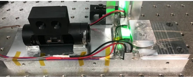
1550 nm 976 nm L1 L2 PBS SAM Chip OC L3 L4 WDM/ ISO LD ISO Outputs
Figure 1.4: Schematic of the dual-comb laser source. Two mode-locked lasers are generated using a pair of parallel waveguides written in an Er-doped ZBLAN chip and a common SAM. LD: laser diode, ISO: isolator.
A magnification of Mp= 4.8 with k = 2 is chosen as it better matches the core diameter ratio between the fibres and the available waveguides. The pump beams are both collimated through a common lens (L4) with a focal length of 13.86 mm (Thorlabs C560TME-B) and are then refocused on the chip with another lens (L3) with a focal length of 60 mm (Thorlabs AC254-060-B), thus providing a nominal magnification of M = 60/13.86 = 4.33. The position of each lens is then slightly adjusted so as to obtain the desired magnification (M = Mp) to allow the injection of pump light into two second-neighbour waveguides separated by 600 µm. The selected waveguides have diameters of 45 µm and 50 µm and are chosen based on their laser efficiency. Figure 1.3c) shows the transmitted pump beams as seen by a beam profiling camera placed at the other end of the chip.
Since each fibre core is positioned 62.5 µm away from the lenses’ principal axis, the collimated beams are leaving L4 with a small angle relative to the axis, as can be seen schematically in Fig. 1.4. The location where each collimated beam hits L3 is therefore dependent on the distance between the lenses, which in turn determines the mean angle of each converging beam after L3. Separating the lenses by a distance equivalent to the sum of the focal lengths allows the central axis of each beam focused on the chip to be collinear with their respective waveguide. This afocal configuration then allows a maximum number of rays converging toward the chip to be within the waveguides’ acceptance angle. Note, however, that the transverse location of each focal point is independent of the lenses’ separation and depends only on the beams’ angle in the collimated space.
A broadband output coupler (OC) mirror (CLaser Photonics) is abutted to the right side of the chip in order to provide a 95 % reflection in the 1.5-1.6 µm signal band. The backside of the OC is AR-coated for the signal wavelength while both sides are AR-coated for 976 nm,
letting more than 95 % of the pump through. The chip itself is AR-coated on both ends for the pump and signal wavelengths (Rocky Mountain Instrument Co.). On the left side of the chip, a pair of AR-coated lenses with focal lengths of 8 mm (L1) (Thorlabs C240TMD-C) and 50 mm (L2) (Asphericon ALL25-50-S-C) are used to image the waveguides onto a SAM with a modulation depth of ∆R = 8 %, a saturation fluence of Fsat = 70 µJ/cm2, a non-saturable loss of 7 %, and a relaxation time of 12 ps (Batop SAM-1550-15-12ps). These lenses provide a magnification of Mc= 0.16 and are also arranged in a near-afocal configuration for the same reasons as for the pump beams. The size reduction allows to increase the fluence on the SAM, and thus its saturation, in order to reach mode-locking. The SAM was chosen empirically by comparing performance with other SAMs from the same manufacturer. Together, the SAM and the OC form a linear cavity with a round-trip time of 1.2 ns and allow both mode-locked lasers to self-start and produce pulse trains with a repetition rate of fr = 822.4 MHz. An AR-coated polarization beam splitter (PBS) (Thorlabs PBS104) is also placed between the lenses to introduce losses in one polarization axis and force operation on the other axis. Polarized fields are preferred in dual-comb interferometry to produce amplitude-stable IGMs.
1.2.2 Characterization
Each laser can generate up to 2 mW of power around 1555 nm. The output beams are directed back toward the fibres through the same set of lenses as the one used for the pump light. They are separated from the counter-propagating pumps using wavelength-division multiplexers (WDM) (Lightcomm HYB-B-S-9815-0-001), which also include a stage of isolation at the signal’s wavelength. Although the output beams could have been left in free space, having two fibre-coupled laser outputs is convenient to easily redirect the light toward other experiments. However, only 10 % of the light is able to make it to the other side of the WDMs in this configuration, mostly because the free-space alignment is optimized for the injection of the pump beams in the waveguides. The 10 % coupling efficiency is estimated by replacing the SAM with another output coupler of equal reflectance and by taking the ratio between the fibre-coupled and free-space powers collected on each end. Nevertheless, 200 µW per output is more than sufficient to perform laboratory-based experiments such as spectroscopy.
Figure 1.5a) shows the power spectrum of each mode-locked laser, or comb source, as mea-sured with an optical spectrum analyzer (Anritsu MS9470A). The 3 dB bandwidth (∆λ3dB) is approximately 9 nm around 1555 nm (1.1 THz) and an excellent overlap between the emission spectra can be observed. The inset reveals the presence of spectral modulation with two main components arising from parasitic etalons: one formed by the parallel faces of the OC and the other formed by the parallel faces of the chip. Even if these surfaces are AR coated, the slight-est reflections are still able to coherently add up at each round-trip in the cavity, resulting in output pulses surrounded by satellites of non-negligible strength. The pulses’ duration has not been measured directly, but a similar mode-locked laser (only one waveguide in operation)