Simulation and Modeling of a Five -Level (NPC)
Inverter Fed by a Photovoltaic Generator and
Integrated in a Hybrid Wind-PV Power System
M. Rezki
Department of Electrical Engineering Faculty of Sciences and Applied Sciences
University of Bouira Bouira, Algeria mohamedrezki197@yahoo.fr
I. Griche
Department of Electrical Engineering Faculty of Sciences and Applied Sciences
University of Bouira Bouira, Algeria griche_issam@yahoo.fr
Abstract—A distributed hybrid coordinated wind photovoltaic
(PV) power system was proposed in this paper. As oil and coal reserves are being depleted whilst at the same time the energy demand is growing, it is important to consider alternative energy generating techniques. Today, the five-level (NPC) inverter represents a good alternative for several industrial applications. To take advantage of the five-level inverter topology and the benefits of renewable energy represented by a photovoltaic generator, a new scheme of these controllers is proposed in this work. This paper outlines the design of a hybrid power system consisting of a solar photovoltaic (PV) and a wind power system. The system is modeled in Matlab Simulink and tested for various conditions. The model and results are discussed in this paper.
Keywords-five-level inverter; solar pv; wind energy; hybrid power system
I. INTRODUCTION
The limited reserves of fossil fuel and environmental pollution have significantly increased the interest in renewable energy sources. Hybrid Wind-PV power systems as a distributed generation network structure have received considerable attention. Such a system has the merit of supplying the difference in time and zone between wind power system and PV system. Hybrid wind-PV systems have become a promising power generation form, as they can improve power reliability in certain remote areas such as deserts, plateaus etc. The hybrid wind-PV generation systems can achieve optimal performance by designing the rational system structure and choosing the coordinated optimization algorithm [1, 2]. Active Power Filter (APF) is the modern solution used to eliminate the undesired current components by injection compensation currents in opposition to them [3]. The universal power converter topology used is the “two level voltage source inverter” [4-6]. Due to power handling capabilities of power semiconductors, these converters are limited to low power applications.
Principally, the design of any APF system pass through three essentials criteria: power inverter topology, current controller and strategy control. Multi level inverters are successfully used in medium and high power applications [7,
8]. Instantaneous power theory [9] and synchronous reference frame detection method [10] have also been widely used. These techniques provide good results under different voltage source conditions but present some drawbacks such as a large calculations number, complex mathematical transformation and difficult practical implementation. The synchronous current detection method is another interesting method. It is concise and requires less computational calculations compared to the two other methods. In this work, the synchronous current detection technique is adopted using a five-level (NPC) inverter after some necessary modifications.
II. THE HYBRID PHOTOVOLTAIC-WIND SYSTEM A schematic presentation of the proposed hybrid energy conversion system is given in Figure 1. The system consists of the following elements: a doubly fed induction generator (DFIG), a wind turbine, a PV generator and an inverter of five-level NPC VSI. The wind turbine converts the wind kinetic energy into mechanical energy, which is transformed in electrical by the DFIG and transmitted to the network. The DFIG rotor is connected to the inverter. The purpose of the multilevel converter is to synthesize a sinusoidal form of the voltage with less harmonic distortion. However, it presents a fluctuating potential of mid-point inducing instability of its input voltages, and then instability of its output voltages. Different PWM algorithms for the five-level NPC VSI are available with the vector modulation strategy with four bipolar carriers [3, 4] to be considered one of the best.
III. HYBRID SYSTEM MODELING
A. Modeling of the Aeroturbine
The wind model used has been developed at RISØ National Laboratory based on the Kaimal spectra [11]. The wind speed is calculated as an average value of the fixed-point wind speed over the whole rotor, and it takes the tower shadow and the rotational turbulences into account. A main component in this model is the normally distributed white noise. Therefore, in order to obtain the same wind time series in all considered simulation tools used in the simulation platform, some investigations have been done. It has been found that the built-in white noise generator from different simulation tools uses a different algorithm and thus a different wind time series is obtained. In order to validate the new white noise generator model, some comparisons have been done. A wind time series for 3600 sec with 0.05 sec sample time is shown in Figure 2.
0 500 1000 1500 2000 2500 3000 3500 6 7 8 9 10 11 12 13 14 time (s) spee d (m /s ) Wind profile
Fig. 2. The wind profile.
The aerodynamic model of the wind turbine (WT) rotor is based on the torque coefficient C or the power coefficientQ C . P The torque coefficient CQ is used to determine the aerodynamic torque directly by using:
3
0.5
wt Q
T R V C (1)
ςhereis the air density, R is the blade radius ,V is the
wind speed,C is the torque coefficient. Alternatively, the Q aerodynamic torque can be determined using the power coefficient C based on: P
2 3
0.5
wt P
T R V C (2)
It is important to underline that both coefficients C and P
Q
C can be function of the tip speed ratio for passive-stall wind turbines or function of tip speed ratio and pitch angle
for active stall and variable pitch/speed wind turbines. The parameters for this model are: blade radius, air density, cut-in and cut-out wind speeds, as shown in appendix. Using a reduced look-up table in respect with the variation of the torque coefficient/power coefficient with the pitch angle ( 10 , the model for the active-stall wind 10 ) turbine is obtained. Imposing a zero value for the pitch angle
the model for passive stall wind turbine can be obtained.
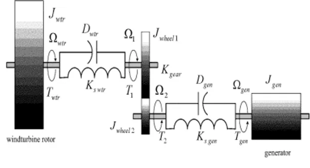
The equivalent model of a wind turbine drive train is presented in Figure 3. The masses correspond to a large mass of the wind turbine rotor, masses for the gearbox wheels and a mass for generator respectively. [12]
Fig. 3. Model of a wind turbine drive train
Taking into account the stiffness and the damping factors for both shafts, the dynamic equations can be written as follows:
1
wtr wtr wtr wtr wtr swtr wtr d T J D K dt (3)
1 1 1 wtr 1 swtr 1 wtr d T J D K dt (4)
2 22 2 gen sgen 2 gen
d d T J D K dt dt (5)
2
gengen gen gen gen sgen gen
d T J D K dt (6) 2 1 1 gear T T K (7) Such as: wtr wtr d dt , gen gen d dt ; i ; 1, 2 i d i dt ; 2 Kgear 1 , (8) Where: Twtris the wind turbine torque, T1 is torque that
goes in the gearbox, T is the torque out from the gearbox, 2 wtr
J is the WT moment of inertia, is the WT mechanical wtr speed, Kswtr is the spring constant indicating the torsion stiffness of the shaft on wind turbine part, Tgen is the generator torque, Jgenis the generator moment of inertia, gen is the generator mechanical speed, Ksgen is the spring constant indicating the torsion stiffness of the shaft on generator part.
B. Modeling of the DFIG
Some of the machine inductances are functions of the rotor speed, whereupon the coefficients of the state-space equations (voltage equations), which describe the behavior of the induction machine, are time varying (except when the rotor is at stand-still). A change of variables is often used to reduce the complexity of these state-space equations. There are several
changes of variables, which are used but there is just one general transformation [8]. This general transformation refers the machine variable to a frame of reference, which rotates at an arbitrary angular velocityg. In this reference frame, the machine windings are replaced with some equivalent windings as shown in Figure 4.
Fig. 4. Induction machine windings in the dq0- reference frame The basic equation of the machine is:
V R I d dt
(9) Based on (9) and using the general transformation, the voltage equations in the arbitrary reference frame can be written as:
V R I d
dt
(10)
The relation between the linkage fluxes and currents is given by:
L I (11) The electromagnetic torque can be obtained starting from eq. (11) and multiplying it from the left with the transpose of the currents vector:
t t t d
t I V I R I I I dt (12) Where:
t iP I V is the instantaneous power. Pcopper
I t R I are the copper losses in the machine blades. mag
td
P I
dt
is the magnetic power stored in machine (due to the variation in time of the magnetic energy) and Pm
I t is the mechanical power.The electromagnetic torque is then:
3 2 m m e sd sq sq sd r r P P T p p i i (13)With p is the number of pole pairs and is the mechanical r speed of the rotor.
C. Flux oriented control of the DFIG
The principle of the vector control requires the knowledge of the exact position of the stream to orient at all times and make it coincide with the direct axis "d" at the same
synchronous rotating speed. To achieve this, two approaches are possible to know the direct control and indirect control [13, 14].
In this work, the indirect control is used. • Choice of reference
By choosing two axes d-q repository related to rotating stator field and aligning the stator flux s illustration with axis d, we can write: 0 ds s qs (14) Therefore, the torque electromagnetic of DFIG is given by:
em sd rq s M C p i i L (15) And the currents in the stator and rotor are:
s ds dr s s dr qr s M i i L L M i i L (16) The active and reactive powers are given by:
s qr s s s s dr s s M P V i L V V M Q i L L (17) In steady state, the terms involving the derivatives of the two-phase rotor currents disappear. We can therefore write:
2 2 ( ) ( ) dr r dr s r qr s s dq r dq s r qd s s s s M V R i g L i L MV M V R i g L i g L L (18)
• Indirect vector control
The indirect method is to replicate reverse the block diagram of the system to be controlled. This builds a block diagram for expressing the rotor voltages functions and powers. The proportional-integral (PI) controller is used to control the DFIG.
Figure 5 shows a closed loop system corrected by a PI controller given in the equation:
( ) i p K R s K S (19)
where Kp: is the proportional gain controller and Ki : is the integral controller gain.
Fig. 6. Block diagram of the current control
D. Modeling of the PV module
Among the modeling methods of PV module, the two-diode model is known to be an accurate model as depicted in Figure 7 [15]. The output current of the module can be described as:
1 s PV d p V IR I I I R (20) Where: 1 01 1 1 exp s 1 d T V IR I I aV (21) And: 2 02 2 2 exp s 1 d T V IR I I a V (22)
Where IPV is the generated current by the incidence of light; I and 01 I are the reserve saturation currents of diode 1 02
and diode 2, respectively. The term I02 is introduced to
compensate for the recombination loss in the depletion region as described in [9]. Other variables are defined as follows:
1 T
V and VT2(both equal toN kT q ) are the thermal voltages s / of the PV module having Nscells connected in series, q is the electron charge (1.60217646 10 C 19 ), k is the Boltzmann
constant (1.3806503 10 23J K/ ) and T is the temperature of
the p n junction in Kelvin. The variables a1and a2represent
the diode ideality constants; a and 1 a represent the diffusion 2
and recombination current component, respectively.
Fig. 7. Two-diode model of PV cell
Although greater accuracy can be achieved using this model than the single diode model [16], it requires the computation of seven parameters, namelyIPV ,I01,I02,R ,p Rs,
1
aanda2.
Recently, a fast and simple two-diode model is proposed in [17]. The simplified current equation is given as:
0 2 s PV p p V IR I I I I R (23) Where: exp exp ( 1) s s p T T V IR V IR I V p V (24) And 2 1 p (25) aIV. FIVE -LEVEL INVERTER
Multilevel inverters are being investigated and recently used for active filter topologies. Five-level inverters are becoming very popular today for most inverter applications, such as machine drives and power factor compensators. These advantages are the reduction of the harmonic content generated by the active filter and the decrease the voltage or current ratings of the semiconductors. Figure 8 shows the circuit topology of a diode-clamped five-level inverter based on the six main switches (T11, T21, T31, T14, T24, T34) of the traditional
two-level inverter, adding two auxiliary switches (T12, T13, T22,
T23, T32, T33) and two neutral clamped diodes on each bridge
arm respectively. The diodes are used to make the connection with the point of reference to obtain midpoint voltages. Such structure allows the switches to endure larger dc voltage input on the premise of not raising the level of their withstand voltage. Moreover, take phase-A as example, three kinds of voltage level Udc/2, 0 and−Udc/2.
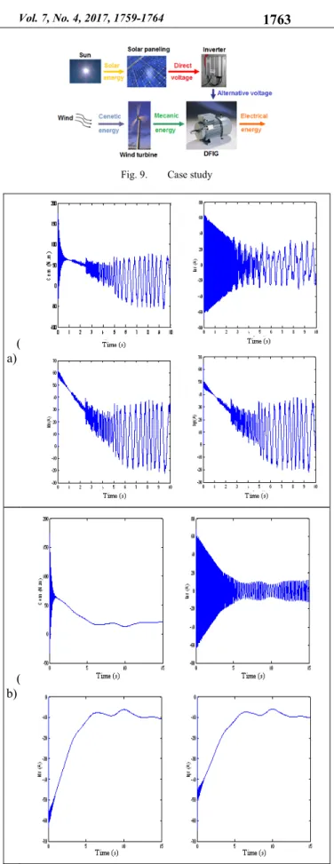
V. CASE STUDY –RESULTS AND DISCUSSION Figure 9 illustrates a schematic representation in its most simple form of hybrid energy conversion chain. This chain is made up of elements, which are:
• A doubly fed induction generator (DFIG).
• A wind turbine converts energy of wind into mechanical energy injected directly to the rotor of DFIG.
• Four photovoltaic solar panels that provide a DC voltage from solar energy. Each panel consists of 36 cells connected in series.
• A three-phase voltage inverter with five levels in NPC structure whose role is to convert the DC voltage of the photovoltaic panels into an alternating voltage supplied to the stator of DFIG.
The schematic model of hybrid system is implemented in Matlab / Simulink.
Figure 10 shows the performance of the vector control and reactive power in the stator applied to a doubly fed induction machine. Note that the active and reactive and current (ird, irq) are identified with their references powers. Proportionality appears between the rotor current quadrature Iqr and active power, and between direct current Idr and reactive power. The quadrature component of flux is almost zero in steady state, which confirms the hypothesis of the vector control. Note the effect of coupling between the two powers P and Q, because that Pref pass (0 to -800) to (t = 1s) there is a small oscillation in the graph of the reactive power Q. It can be noted that the electromagnetic torque reacts spontaneously when there is a demand for active power, reactive power independent. In addition, the voltage response time issued by the panel is big. The voltage Va is a consequence of the input voltage of the PV panel. We see an appearance of ripples levels of the stator flux, the rotor current and the electromagnetic torque. This is due to the nature of the voltage of the solar panel.
Figure 10 shows the performance of the vector control and reactive power in the stator applied to a doubly fed induction machine. Note that the active and reactive and current (ird, irq) are identified with their references powers. Proportionality appears between the rotor current quadrature Iqr and active power, and between direct current Idr and reactive power. The quadrature component of flux is almost zero in steady state, which confirms the hypothesis of the vector control. Note the effect of coupling between the two powers P and Q, because that Pref pass (0 to -800) to (t = 1s) there is a small oscillation in the graph of the reactive power Q. It can be noted that the electromagnetic torque reacts spontaneously when there is a demand for active power, reactive power independent. In addition, the voltage response time issued by the panel is big. The voltage Va is a consequence of the input voltage of the PV panel. We see an appearance of ripples levels of the stator flux, the rotor current and the electromagnetic torque. This is due to the nature of the voltage of the solar panel.
Fig. 9. Case study
( a)
( b)
Fig. 10. Simulation results without MPPT and a) without and b) with vector control)
VI. CONCLUSIONS
A distributed coordinated hybrid wind-PV system structure based on DFIG representing an isolated renewable energy site is investigated in this paper. Five-level (NPC) inverter neutral-point diode clamped topology with the integration of a PV generator is proposed to provide a great improvement in the quality of the output voltages. The doubly-fed induction machine for the five level inverter is flux oriented controlled in order to improve the inverter’s performance. For future work, it is recommended to examine the performance of the proposed methodology by using other techniques such as fuzzy logic and sliding mode controller.
REFERENCES
[1] O. Vodyakho, T. Kim, S. Kwak, “Comparaison of the space vector current controls for shunt active power filters”, IET Power Electronics, Vol. 2,No. 6, pp. 653–664, 2009
[2] U. Khruathep, S. Premrudeepreechacharn, Y. Kumsuwan, “Implementation of shunt active power filter using source voltage and source current detection”, ICIEA 2008, 3rd IEEE Conference on Industrial Electronics and Applications, Singapore, 3-5 June 2008 [3] E. E. El-Kholy, A. El-Hefnawy, H. M. Mahrous, “Three-phase active
power based on current controlled voltage source inverter”, Electric Power and Energy Systems, Vol. 28, pp. 537-547, 2006
[4] N. G. Apte, V. N. Bapat, A. N. Jog, “A shunt active filter for reactive power compensation and harmonic mitigation”, IEEE 7th International
Conference on Power Electronics, pp. 672-676, 2008
[5] S. Bhattacharya, T. M Frank, D. M Divan, B. Banerjee, “Active filter system implementation”, IEEE Transactions on Industry Applications, Vol. 4, No. 5, pp. 47-63, 1998
[6] M. Routimo, M. Salo, H. Tuusa, “Comparaison of voltage source and current source shunt active power filter”, IEEE Transactions on Power Electronics, Vol. 22, No. 2, pp. 636-643, 2007
[7] O. Vodyakho, C. C. Mi, “Three-level inverter-based shunt active power filter in three-phase three-wire and four-wire systems”, IEEE Transactions on Power Electronics, Vol. 24, No. 5, pp. 1350-1363, 2009
[8] O. Vodyakho, D. Hackstein, A. Steimel, T. Kim, “Novel direct current-space vector control for shunt active power filters based on three-level inverters”, IEEE Transactions on Power Electronics, Vol. 23, No. 4, pp. 1868-1873, 2008
[9] R. H. Herrera, P. Salemeron, H. Kim, “Instantaneous reactive power theory applied to active power filter compensation: different approaches, assessment, and experimental results”, IEEE Transactions on Industrial Electronics, Vol. 55, No. 1, pp. 184-196, 2008
[10] S. Bhattachrya, D. Divan, “Synchronous frame based controller implementation for a hybrid series active filter systems”, IEEE Thirtieth IAS Annual Meeting Industry Applications Conference IAS '95, Vol. 3, pp. 2531-2540, 1995
[11] A. Shaltout, “Analysis of torsional torques in starting of large squirrel cage induction motors”, IEEE Transactions on Energy Conversion, Vol. 9, No. 1, pp. 135-141, 1994
[12] A. S. Neris, N. A. Vovos, G. B. Giannakopoulos, “A variable speed wind energy conversion scheme for connection to weak AC systems”, IEEE Transactions on Energy Conversion, Vol. 14, No. 1, pp. 122-127, 1999
[13] T. Petru, T. Thiringer, “Modeling of wind turbines for power system studies”, IEEE Transactions on Power Systems, Vol. 17, No. 4, pp. 1132–1139, 2002
[14] S. Seman, S. Kanerva, J. Niiranen, A. Arkkio, “Transient analysis of wind power doubly fed induction generator using coupled field circuit model”, 16th International Conference on Electrical Machines ICEM 2004, Cracow, Poland, September 5-8, 2004
[15] D. S. H. Chan, J. C. H. Phang, “Analytical methods for the extraction of solar-cell single- and double-diode model parameters from I-V characteristics”, IEEE Transactions on Electron Devices, Vol. 34, No. 2, pp. 286-293, 1987
[16] K. Ishaque, Z. Salam, H. Taheri, “Simple, fast and accurate twodiode model for photovoltaic modules,” Solar Energy Materials and Solar Cells, Vol. 95, No. 2, pp. 586-594, 2011
[17] KC200GT High Efficiency Multicrystal Photovoltaic Module datasheetKyocera, available at http://www.kyocera.com.sg/products/ solar/ pdf/kc200gt.pdf