OATAO is an open access repository that collects the work of Toulouse
researchers and makes it freely available over the web where possible
Any correspondence concerning this service should be sent
to the repository administrator:
[email protected]
This is a Publisher’s version published in:
http://oatao.univ-toulouse.fr/27485
To cite this version:
Korb, Matias de Angelis and Tarragó, Diego Pereira and Krischer, Cesar
Augusto and Duluard, Sandrine Nathalie
and Ansart, Florence
and
Malfatti, Célia de Fraga Effect of High-Temperature Exposure on Degradation
of La0.6Sr0.4CoO3 Coated Metallic Interconnects for ITSOFC and SOEC.
(2020) Materials Research, 23 (3). 1-7. ISSN 1516-1439
Effect of High-Temperature Exposure on Degradation of La
0.6Sr
0.4CoO
3Coated Metallic
Interconnects for ITSOFC and SOEC
Matias de Angelis Korba,b*, Diego Pereira Tarragóa, Cesar Augusto Krischera, Sandrine Duluardc, Florence Ansartc, Célia de Fraga Malfattia
aUniversidade Federal do Rio Grande do Sul, Programa de Pós-Graduação em Engenharia de Minas,
Metalúrgica e de Materiais, 91501-970, Porto Alegre, RS, Brasil
bInstituto Federal de Educação, Ciência e Tecnologia Sul - rio - grandense - Câmpus Charqueadas,
cCIRIMAT, Université de Toulouse, CNRS, Université Toulouse 3 Paul-Sabatier, 118 route de Narbonne,
F-31062, Toulouse cedex 9, France
Received: February 27, 2020; Revised: June 7, 2020; Accepted: June 10, 2020
Previous studies showed the formation of new phases affecting the electrical properties of LSC thin films deposited on stainless steel substrates, which are commonly tested for ITSOFC and SOEC interconnects. A 4.3 μm thick La0.6Sr0.4CoO3 coating was deposited on AISI430 steel by spray pyrolysis, followed by heat treatment (800°C/2h) and an oxidation in air (800°C/96h). The La0.6Sr0.4CoO3 phase interacted with the metallic substrate and formed SrCrO4, causing degradation of the perovskite into La0.9Sr0.1CoO3. An EDS mapping showed Sr and Cr enrichment in the coating/substrate interface. TG analysis indicated a lower mass gain for the coated substrate. The total ASR at 800°C of the interconnect before and after oxidation was 3.23 Ω.cm2 and 3.98 Ω.cm2, respectively. The Ea underwent very small variation, remaining around 0.24 eV (T≤300°C) and 0.65 eV (T≥400°C). The reaction of Cr from the substrate and Sr from LSC seems to have impaired the performance of the interconnect.
Keywords: steel intreconnect, coating, lanthanum cobaltite, impedance spectroscopy.
1. Introduction
Metallic interconnects have been used in intermediate temperature solid oxide fuel cells (ITSOFC) and solid oxide electrolysis cells (SOECs) with operating temperatures between 600°C and 800°C. The maximum total area specific resistance (ASR) for the application is 0.1 Ω.cm2 in the whole temperature range. In comparison to ceramic materials, metallic materials present a higher electrical conductivity, higher mechanical resistance, easier manufacturing, and lower cost1-4. Many heat resistant alloys, such as chromium, nickel or cobalt-based alloys, have been studied for this application. Ferritic stainless steels were selected due to their good oxidation resistance, thermal expansion coefficient (TEC, 10–14x10-6 K-1), compatibility with the other components, and low cost compared to other alloys5,6. However, under operating conditions, in oxidizing and reducing atmospheres, these metallic alloys present a oxidation rate that follows the growth of a chromium oxide layer with high electrical resistance, and chromium vaporization impairing the ITSOFC and SOEC performance7-12.
One alternative to protect the ferritic stainless steel from high-temperature oxidation is applying a protective oxide coating to its surface13-15. These coatings must act as a barrier to avoid chromium diffusion from the metallic substrate and oxygen diffusion to the metallic alloy, maintaining thermomechanical and chemical stability during fuel cell operation16. The obtained coatings have the advantages of easy deposition and a cost lower than heat resistant metallic
alloys that need to have specific compositions and to be free of undesirable impurities17.
The main types of coatings include rare earth oxides18-20, perovskites21 and spinels22-26. Among these materials, the perovskite oxides, such as the ones based on lanthanum chromite (LCr; LaCrO3)27, strontium-doped lanthanum manganite (LSM; La1-xSrxMnO3)28, strontium-doped lanthanum cobaltite (LSC; La1-xSrxCoO3)29, and strontium-doped lanthanum ferrite (LSF; La1-xSrxFeO3)17, are currently of great interest due to the possibility combining different elements to obtain an electrical conductivity compatible with the specifications of the ITSOFC5. The main methods used for coating applications are: dip coating30, chemical vapor deposition31, pulsed laser deposition32, plasma spraying33,34, screen printing, slurry coating35, sputtering36,37, electrodeposition38, and spray pyrolysis29,39,40.
Perovskite cobaltite coatings interact with the stainless steel and a new phase is formed, SrCrO429,41. However, the electrical behavior of these phases needs further investigation given that some authors42 showed a beneficial effect whereas others43 showed that this phase is non-conductive and that SrCrO4 formation leads to lower conductivity.
As a continuation of our previous investigation29, the purpose of this study was to investigate the effect of oxidation on AISI 430 ferritic stainless steel coated with La0.6Sr0.4CoO3 (LSC), obtained by spray pyrolysis. The electrical conductivity at high temperatures was evaluated in an inert atmosphere using electrochemical impedance spectroscopy (EIS). Additionally, the phase formation and stability of LSC during an air oxidation process were analyzed.
*e-mail: [email protected]
Korb et al.
2 Materials Research
2. Experimental
2.1 Substrate preparation
In this work, 1 mm thick with 1 cm2 AISI 430 ferritic stainless steel was used as a substrate for the coating. The chemical composition of the AISI 430 is 16.44 Cr, 0.06 C, 0.43 Mn, 0.036 Mo, 0.40 Ni, 0.02 Co, 0.002 Al, and 0.02 Nb (wt %), with the balance Fe. The samples were cut into 10 x 10 mm pieces. SiC paper (120–600 – grid) was used to sand these pieces.
2.2 Coating deposition
(La,Sr)CoO3 films were deposited using a homemade spray pyrolysis apparatus on ferritic stainless steel samples. The precursor solution was prepared from lanthanum nitrate hexahydrate (La(NO3).6H2O) (≥ 99%, Vetec Química Fina, Brazil), strontium nitrate (Sr(NO3)2) (≥ 99%, Vetec Química Fina, Brazil) and cobalt nitrate hexahydrate (Co(NO3)2.6H2O) (≥ 99%, Vetec Química Fina, Brazil) to obtain the desired stoichiometry (La0.6Sr0.4CoO3). This solution was placed in a reservoir connected to an atomizer nozzle. The precursor solution was sprayed onto the ferritic stainless steel samples, which were placed on a heated metal plate at the desired temperature. The metallic substrate was placed under the spray nozzle to obtain a more homogeneous film deposition. The deposition parameters were shown in our previous paper29.
The coatings obtained by this method were amorphous. To obtain a crystalline phase composed of La0.6Sr0.4CoO3 (LSC), the films were heated to 800°C in air for 2 hours, using a 10 °C min-1 heating rate.
2.3 Coating characterization
The coating surface morphologies and cross-sections were examined by scanning electron microscopy (SEM) (JEOL - JSM 6060). The chemical composition of the films
was analyzed by energy dispersive spectroscopy (EDS) (JSM 5800). The structural characteristics of the coatings before and after the oxidation test were analyzed by XRD (Philips X-Ray Analytical Equipment X’Pert-MPD System). The scans were collected in the 2Ɵ range (20-75°) with a 0.02° variation.
The oxidation behavior was observed by thermogravimetric analysis (TG) and by a furnace test on both the coated and uncoated samples. The TG analysis was performed for 24 hours at 800°C in air to measure the thermal history, whereas the furnace test was 96 hours at 800°C in air. The test was conducted with a 10 °C min-1 heating rate.
Impedance spectroscopy analyses were performed for coated samples before and after oxidation at 800°C for 96 hours. A gold sputtered cover was deposited on both sides of coated substrates to act as a contact electrode, avoiding double layer effects. The electrical measurements were carried out in an argon atmosphere, to prevent further oxidation, and the samples were stabilized for 1 hour at each temperature, in the range of 100°C to 800°C. An impedance analyzer (7260 Impedance Analyser from Materials Mates) was used in the 1 Hz to 10 MHz frequency range, at OCP with a +/- 20 mV AC amplitude using a two-probe set.
3. Results and Discussion
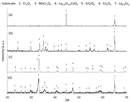
The XRD patterns obtained in this study are exhibited in Figure 1. Comparing the uncoated substrate before and after oxidation for 96 hours at 800°C (Figure 1a and Figure 1b), significant amounts of two main oxides were formed during the oxidation process. Intense peaks of Cr2O3 (PDF nº 00-038-1479) were detected with equally intense peaks of MnCr2O4 (PDF nº 01-075-1614), in agreement with the oxidation products of AISI 430 found by Rufner et al.44.
After spray pyrolysis at 550°C for 30 min, the deposited coating has no distinct XRD reflections and the coating was
amorphous at the XRD analysis scale (not shown). However, after heat treatment at 800°C for 2 hours in air (Figure 1c), it was possible to observe the formation of the desired phase, La0.6Sr0.4CoO3 (LSC) perovskite (PDF nº 01-089-5719), as expected from the precursor solution preparation fractions. Moreover, the substrate phase could be distinguished (PDF nº 01-087-0722) among the perovskite peaks. Also, very low-intensity peaks were observed and can be attributed to a very low concentration of SrCrO4 (PDF nº 00-015-0356), which appears to start forming even with a time as low as 2 hours at 800°C (heat treatment). The formation of SrCrO4 may occur due to the hexavalent chromium ion, which diffuses through the coating45. Residual Co
3O4 (PDF nº 03-065-3103) that was not fully incorporated into the perovskite lattice was observed.
Considering the result of the LSC coated sample, it is noted that the oxidation at 800°C for 96 hours (Figure 1d) caused some modifications in the phases present in the film. First, the dissolution and incorporation of Co3O4, which was no longer detected in the pattern. Also, the more intense peaks of SrCrO4 may indicate the formation of higher amounts of this compound, followed by a loss of strontium in the LSC perovskite, resulting in the La0.9Sr0.1CoO3 composition (PDF nº 00-028-1229). The presence of Sr in the LSC coating was determinant in the evolution of phases in the surface of the AISI 430 steel due to the reactivity of strontium oxide (SrO). The SrO rapidly reacted with Cr2O3, forming SrCrO4, which seemed to have suppressed the formation of the MnCr2O4 phase. According to Chen et al.46, the formation of SrCrO4 at the interface is thermodynamically favorable. However, as described above, it cost the perovskite a severe Sr impoverishment.
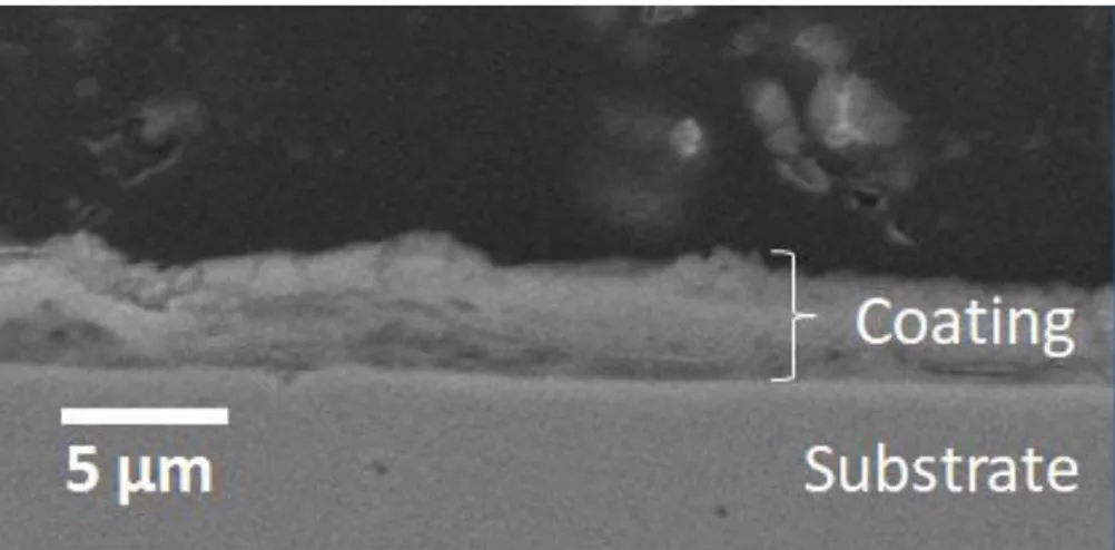
Figure 2 shows a cross-section of the AISI 430 coated with LSC after heat treatment for 2 hours at 800°C. The film thickness is heterogeneous, the average thickness was 4.3 ± 0.9 μm. The irregular shapes of formed films are related to the spray pyrolysis process. The small droplets land on the substrate surface to undergo a pyrolytic reaction. Therefore, isolated agglomerates with irregular shapes are formed47.
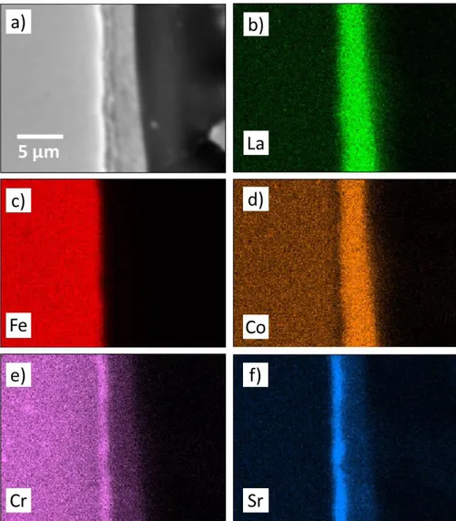
Figure 3 shows images obtained by elemental distribution using EDS for cross-sections of the LSC coated substrate after heat treatment for 2 hours at 800°C. The elemental
distribution demonstrates the presence of the coating on top of the substrate surface (Figure 3b, 3d, 3e, and 3f). In Figure 3e and 3f, it is possible to observe Sr and Cr enrichment in the substrate/coating interface. This possibly indicates the location of the SrCrO4, detected in the XRD analysis (Figure 1c), which starts with the reaction between the Sr from perovskite and the Cr from the metallic substrate48. Liu and Konysheva49 indicated through impedance analysis, that SrCrO4 precipitation occurs by growing a layer between the Sr rich and Cr rich interfaces. In previous work29, a computational simulation was performed, that showed the stability of the SrCrO4 oxide when a system containing Sr and variable amounts of Cr was exposed to an environment rich in O2 at 800°C, causing perovskite degradation from the La0.6Sr0.4CoO3 phase to the La0.9Sr0.1CoO3 phase, in agreement with the observed degradation of the perovskite in the XRD results. Furthermore, Yokokawa et al.43 showed that SrCrO
4 formation is thermodynamically favored for perovskites containing less stable tetravalent ions (Fe4+ or Co4+). Additionally, the presence of Cr was verified in the coating region (Figure 3e), suggesting that some amount of Cr ions diffuse from the substrate through the coating.
The TG analysis (Figure 4) shows that the coated substrate presented a lower mass gain than the uncoated substrate after 24 hours at 800°C, which may be associated with an increase in the oxidation resistance of the surface coated with La0.6Sr0.4CoO3. The uncoated substrate had a mass gain of 1.745 mg cm-2, while the coated substrate had a mass gain of 0.215 mg cm-2. The initial oxidation (from t=0 to t= 88 minutes) is larger for the uncoated sample, which may be due to free oxidation of the substrate, probably associated with the formation of phases that can be observed in Figure 1b. The initial oxidation (from t=0 to t= 147 minutes) for the coated substrate may be due to oxidation of the uncoated side because the coating was deposited on one side of the metallic substrate and the SrCrO4 formation, that can be observed in Figure 1c, which according to Chen et al.46, occurs through the reaction of oxides (Cr and Sr) with O2 (g). Both substrates, uncoated from t=197 to t=855 minutes and coated from t=147 to t=951 minutes, showed a mass loss, which is associated with chromium vaporization from the metallic substrate50-52. Quadakkers et al.48 observed that chromium
Korb et al.
4 Materials Research
transport happens due to volatile species, such as CrO3, and Cr2(OH)2 in chromium-based alloys at 950°C. According to Kurokawa et al.53, the density of ceramic coatings deposited on stainless steel substrates dominates the suppression of chromium release rate. In this sense, it may be inferred that the coating obtained in this work was not effective to promote a barrier to chromium vaporization, because the chromium release rate observed in the TGA (between t~150 min and t~900 min) is similar to the coated and uncoated substrates.
If the barrier was effective, it would be expected a smaller chromium release rate in the coated substrate, even with only one side protected. Starting at 865 minutes, the uncoated substrate showed a mass gain associated with the growth of Cr2O3 and/or Fe2O354. The distinction, by XRD, between Fe2O3 and Cr2O3 is not easy because of the similarities of the cell parameters51,55. The coated substrate, starting at 1082 minutes, showed a mass gain, which is associated with continued SrCrO4 growth.
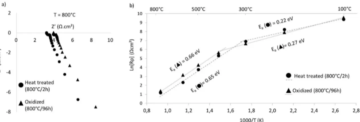
The impedance spectroscopy results of coated samples before and after oxidation at 800°C for 96 hours presented a resistance, as illustrated in the Nyquist diagram obtained at 800°C, shown in Figure 5a. From the resistance measured at different temperatures the Arrhenius diagram was obtained and can be seen in Figure 5b. For the coated heat-treated substrate (800 °C/2h) before oxidation, a decrease in the area specific resistance (ASR) was observed, with a rise in the temperature, from 11531 Ωcm2 at 100°C to 3.23 Ωcm2 at 800 °C. After oxidation at 800°C for 96 hours in air, the electrical resistance values at 100°C and 800°C were 14324 Ωcm2 and 3.98 Ωcm2, respectively. Both results indicate that the LSC coated AISI 430 steels present semiconductor
Figure 3. Elemental distribution of the cross-section of LSC coated substrate: (a) SEM-SE image (b) La (c) Fe (d) Co (e) Cr (f) Sr.
Figure 4. TGA curves of the coated heat-treated substrate and uncoated substrate at 800°C for 24 h in air.
behavior after the heat treatment (800 °C/2h) and after oxidation (800 °C/96h). Wu et al.56 determined, using a DC four-wire method, that strontium-doped lanthanum cobaltites (La1-xSrxCoO3) deposited on a samarium-doped ceria (SDC) electrolyte present a metallic-like conduction behavior, decreasing conductivity with rising temperature. De Souza and Kilner57 tested the oxygen diffusion of La
1-xSrxCoO3 pellets, considering a band model where electrons occupy a wide and partially filled band. This seems to agree with the metallic-like behavior because large number of carriers may be available. Instead, the additional SrCrO4 phase detected in the XRD and other secondary phases usually has typical semiconductor behavior and is less conductive than LSC, causing deleterious effects on the coating conductivity when present43,49. Liu and Konisheva49 analyzed the influence of SrCrO4 in the deterioration of lanthanum cobaltite cathodes in half cells and reported the semiconductor like behavior of SrCrO4. They also measured its total conductivity as 0.182 mS cm-1 at 800°C, which is 6 orders of magnitude lower than the lanthanum cobaltite cathode. In this study, considering the average thickness of 4.3 μm, the total conductivities of the samples at 800°C were 0.124 mS cm-1 after heat treatment (800 °C/2h) and 0.100 mS cm-1 after oxidation (800 °C/96h), which are values close to those cited above. This suggests that the small amount of SrCrO4, detected by very low intensity peaks in XRD analysis before the oxidation (Figure 1c), is already enough to cause severe deterioration on the total ASR. In turn, it can be related to the formation of a SrCrO4 continuous layer in the perovskite/steel interface, as observed in the EDS mapping before oxidation (Figure 3e and 3f), instead of a random phase distribution. After the oxidation at 800°C for 96h, this SrCrO4 layer is not greatly increased, due to the depletion of Sr in the perovskite, but still resulted in a slight increase in the total ASR.
The presence of SrCrO4 seems to drastically deteriorate the performance of the LSC coating with respect to the electrical conductivity. The obtained values of ASR are too high. For a demanding role such as an ITSOFC interconnect, the total interconnect ASR must remain below 0.1 Ωcm2 for proper performance31. However, compared to insulating phases such as Cr2O3 and MnCr2O4, some authors may consider the formation of SrCrO4 somewhat favorable to the overall performance of the interconnect42,58 because the service life may be considered.
The activation energy (Ea) values, indicated in Figure 5b, are virtually the same for samples before and after oxidation. In both samples, a variation in the Ea values occurred between 300°C and 400°C.At low temperatures (T≤300°C) the Ea before oxidation was 0.22 eV and varied very slightly to 0.27 eV after oxidation. At higher temperatures (T≥400°C) the Ea increased to 0.65 eV and 0.66 eV, respectively. Wu et al.56 observed a change in the slope, provoked by the shift in Ea, and attributed it to a crystal transformation of LSC from a rhombohedral to a cubic structure. The Ea shift, however, occurred at higher temperatures than what was determined in this work (300°C to 400°C) and a much lower Ea was also attributed to LSC, on the order of 10-2 eV. An Ea of 0.35 eV, obtained by Song et al.59 at lower temperatures, was attributed to the formation of Cr2O3. Higher Ea values (>1.0 eV) attributed to LSC were also reported when the oxygen reduction is considered. Yet, this work assumed that only electronic conduction occurred in the sample since the measurements were carried out in an argon flow.
4. Conclusions
LSC coatings were successfully deposited on an AISI 430 steel surface by spray pyrolysis, with an average thickness of 4.3 ± 0.9 μm. Heat treatment at 800°C for 2 hours in air led to the formation of the desired La0.6Sr0.4CoO3 phase. However, it also initiated a reaction between the Sr in the coating and the Cr in the substrate, forming insulating SrCrO4, which grows larger during the oxidation process (800°C for 96 hours). This resulted in a Sr deficient LSC and decreased electrical properties in the coating. The ASR at 800°C after heat treatment was 3.23 Ω.cm2 and showed only a small rise to 3.98 Ω.cm2 after the oxidation process at 800°C for 96h. The high-temperature reaction of Cr from the substrate and Sr from the LSC, forming SrCrO4, seriously impaired the interconnect performance, preventing the joint use of these materials in ITSOFC and SOEC devices.
5. Acknowledgments
This work was supported by the CAPES (the Brazilian Government agency for the development of human resources); CAPES PROEX [Number 23038.000341/2019-71]; and CNPq (the Brazilian National Council for Scientific and Technological Development).
Korb et al.
6 Materials Research
6. References
1. Qu W, Li J, Ivey DG. Sol–gel coatings to reduce oxide growth in interconnects used for solid oxide fuel cells. J Power Sources. 2004;138(1-2):162-73. http://dx.doi.org/10.1016/j. jpowsour.2004.06.063.
2. Geng SJ, Zhu JH, Lu ZG. Evaluation of several alloys for solid oxide fuel cell interconnect application. Scr Mater. 2006;55(3):239-42. http://dx.doi.org/10.1016/j.scriptamat.2006.04.008. 3. Zhu WZ, Deevi SC. Opportunity of metallic interconnects for
solid oxide fuel cells: a status on contact resistance. Mater Res Bull. 2003;38(6):957-72. http://dx.doi.org/10.1016/S0025-5408(03)00076-X.
4. Ni M, Leung MKH, Leung DYC. Energy and exergy analysis of hydrogen production by solid oxide steam electrolyzer plant. Int J Hydrogen Energy. 2007;32(18):4648-60. http://dx.doi. org/10.1016/j.ijhydene.2007.08.005.
5. Shaigan N, Qu W, Ivey DG, Chen W. A review of recent progress in coatings, surface modifications and alloy developments for solid oxide fuel cell ferritic stainless steel interconnects. J Power Sources. 2010;195(6):1529-42. http://dx.doi.org/10.1016/j. jpowsour.2009.09.069.
6. Fergus JW. Metallic interconnects for solid oxide fuel cells. Mater Sci Eng A. 2005;397(1-2):271-83. http://dx.doi.org/10.1016/j. msea.2005.02.047.
7. Liu Y. Performance evaluation of several commercial alloys in a reducing environment. J Power Sources. 2008;179(1):286-91. http://dx.doi.org/10.1016/j.jpowsour.2007.12.067.
8. Meulenberg WA, Uhlenbruck S, Wessel E, Buchkremer HP, Stöver D. Oxidation behaviour of ferrous alloys used as interconnecting material in solid oxide fuel cells. J Mater Sci. 2003;38(3):507-13. http://dx.doi.org/10.1023/A:1021879800937. 9. Horita T, Yamaji K, Yokokawa H, Toji A, Uehara T, Ogasawara
K, et al. Effects of Si and Al concentrations in Fe–Cr alloy on the formation of oxide scales in H2–H2O. Int J Hydrogen Energy. 2008;33(21):6308-15. http://dx.doi.org/10.1016/j. ijhydene.2008.07.118.
10. Hua B, Kong Y, Zhang W, Pu J, Chi B, Jian L. The effect of Mn on the oxidation behavior and electrical conductivity of Fe–17Cr alloys in solid oxide fuel cell cathode atmosphere. J Power Sources. 2011;196(18):7627-38. http://dx.doi.org/10.1016/j. jpowsour.2011.05.007.
11. Chatterjee D, Biswas S. Development of chromium barrier coatings for solid oxide fuel cells. Int J Hydrogen Energy. 2011;36(7):4530-9. http://dx.doi.org/10.1016/j.ijhydene.2010.04.114. 12. Chen K, Bo W, Hyodo J, Ishihara T, Jiang SP. Chromium
deposition and poisoning of LSCF and LSM oxygen electrodes of solid oxide electrolysis cells. ECS Trans. 2015;68(1):793-9. http://dx.doi.org/10.1149/06801.0793ecst.
13. Larring Y, Norby T. Spinel and perovskite functional layers between plansee metallic interconnect (Cr‐5 wt % Fe‐1 wt % Y 2 O 3) and ceramic (La0.85Sr0.15) 0.91MnO3 cathode materials for solid oxide fuel cells. J Electrochem Soc. 2000;147:3251-6. http://dx.doi.org/10.1149/1.1393891.
14. Stanislowski M, Froitzheim J, Niewolak L, Quadakkers WJ, Hilpert K, Markus T, et al. Reduction of chromium vaporization from SOFC interconnectors by highly effective coatings. J Power Sources. 2007;164(2):578-89. http://dx.doi.org/10.1016/j. jpowsour.2006.08.013.
15. Piccardo P, Gannon P, Chevalier S, Viviani M, Barbucci A, Caboche G, et al. ASR evaluation of different kinds of coatings on a ferritic stainless steel as SOFC interconnects. Surf Coat Tech. 2007;202(4-7):1221-5. http://dx.doi.org/10.1016/j. surfcoat.2007.07.096.
16. Yang Z, Xia G-G, Maupin GD, Stevenson JW. Conductive protection layers on oxidation resistant alloys for SOFC interconnect applications. Surf Coat Tech. 2006;201(7):4476-83. http://dx.doi.org/10.1016/j.surfcoat.2006.08.082.
17. Palcut M, Mikkelsen L, Neufeld K, Chen M, Knibbe R, Hendriksen PV. Efficient dual layer interconnect coating for high temperature electrochemical devices. Int J Hydrogen Energy. 2012;37(19):14501-10. http://dx.doi.org/10.1016/j. ijhydene.2012.07.038.
18. Ramanathan LV, Pillis MF, Fernandes SMC. Role of rare earth oxide coatings on oxidation resistance of chromia-forming alloys. J Mater Sci. 2008;43(2):530-5. http://dx.doi.org/10.1007/ s10853-007-1855-8.
19. Huang K, Hou PY, Goodenough JB. Reduced area specific resistance for iron-based metallic interconnects by surface oxide coatings. Mater Res Bull. 2001;36(1-2):81-95. http:// dx.doi.org/10.1016/S0025-5408(01)00506-2.
20. Fernandes SMC, Ramanathan LV. Rare earth oxide coatings to decrease high temperature degradation of chromia forming alloys. Mater Res. 2004;7(1):135-9. http://dx.doi.org/10.1590/ S1516-14392004000100018.
21. Jan D-J, Lin C-T, Ai C-F. Structural characterization of La0.67Sr0.33MnO3 protective coatings for solid oxide fuel cell interconnect deposited by pulsed magnetron sputtering. Thin Solid Films. 2008;516(18):6300-4. http://dx.doi.org/10.1016/j. tsf.2007.12.129.
22. Masi A, Bellusci M, McPhail SJ, Padella F, Reale P, Hong J-E, et al. The effect of chemical composition on high temperature behaviour of Fe and Cu doped Mn-Co spinels. Ceram Int. 2017;43(2):2829-35. http://dx.doi.org/10.1016/j. ceramint.2016.11.135.
23. Mah JCW, Muchtar A, Somalu MR, Ghazali MJ, Raharjo J. Formation of sol–gel derived (Cu,Mn,Co)3O4 spinel and its electrical properties. Ceram Int. 2017;43(10):7641-6. http:// dx.doi.org/10.1016/j.ceramint.2017.03.060.
24. Ludwig GA, Korb MA, Lima DAS, Macías MA, Gauthier GH, Malfatti CF. Protective coatings for AISI 430 stainless steel at high temperatures using perovskite oxides La0.6Sr0.4CoO3 on spinel type oxide NiFe2O4. Ceram Int. 2015;41(10):14561-73. http://dx.doi.org/10.1016/j.ceramint.2015.07.173.
25. Zhu JH, Lewis MJ, Du SW, Li YT. CeO2-doped (Co,Mn)3O4 coatings for protecting solid oxide fuel cell interconnect alloys. Thin Solid Films. 2015;596:179-84. http://dx.doi.org/10.1016/j. tsf.2015.07.085.
26. Akanda SR, Walter ME, Kidner NJ, Seabaugh MM. Lifetime prediction for manganese cobalt spinel oxide coatings on metallic interconnects. Thin Solid Films. 2014;565:237-48. http://dx.doi.org/10.1016/j.tsf.2014.06.021.
27. Brylewski T, Dabek J, Przybylski K, Morgiel J, Rekas M. Screen-printed (La,Sr)CrO3 coatings on ferritic stainless steel interconnects for solid oxide fuel cells using nanopowders prepared by means of ultrasonic spray pyrolysis. J Power Sources. 2012;208:86-95. http://dx.doi.org/10.1016/j.jpowsour.2012.02.015. 28. Conceição L, Souza MMVM. Synthesis of La0.7Sr0.3MnO3
thin films supported on Fe–Cr alloy by sol–gel/dip-coating process: evaluation of deposition parameters. Thin Solid Films. 2013;534:218-25. http://dx.doi.org/10.1016/j.tsf.2013.02.124. 29. de Angelis Korb M, Savaris ID, Feistauer EE, Barreto LS, Heck
NC, Müller IL, et al. Modification of the La0.6Sr0.4CoO3 coating deposited on ferritic stainless steel by spray pyrolysis after oxidation in air at high temperature. Int J Hydrogen Energy. 2013;38(11):4760-6. http://dx.doi.org/10.1016/j. ijhydene.2013.02.019.
30. Xu Y, Wen Z, Wang S, Wen T. Cu doped Mn–Co spinel protective coating on ferritic stainless steels for SOFC interconnect applications. Solid State Ion. 2011;192(1):561-4. http://dx.doi. org/10.1016/j.ssi.2010.05.052.
31. Fontana S, Amendola R, Chevalier S, Piccardo P, Caboche G, Viviani M, et al. Metallic interconnects for SOFC: characterisation of corrosion resistance and conductivity evaluation at operating temperature of differently coated
alloys. J Power Sources. 2007;171(2):652-62. http://dx.doi. org/10.1016/j.jpowsour.2007.06.255.
32. Kruk A, Adamczyk A, Gil A, Kąc S, Dąbek J, Ziąbka M, et al. Effect of Co deposition on oxidation behavior and electrical properties of ferritic steel for solid oxide fuel cell interconnects. Thin Solid Films. 2015;590:184-92. http://dx.doi.org/10.1016/j. tsf.2015.07.023.
33. Waluyo NS, Park S-S, Song R-H, Lee S-B, Lim T-H, Hong J-E, et al. Protective coating based on manganese–copper oxide for solid oxide fuel cell interconnects: plasma spray coating and performance evaluation. Ceram Int. 2018;44(10):11576-81. http://dx.doi.org/10.1016/j.ceramint.2018.03.220.
34. Yang Y-J, Wen T-L, Tu H, Wang D-Q, Yang J. Characteristics of lanthanum strontium chromite prepared by glycine nitrate process. Solid State Ion. 2000;135(1-4):475-9. http://dx.doi. org/10.1016/S0167-2738(00)00402-1.
35. Kim J-H, Song R-H, Hyun S-H. Effect of slurry-coated LaSrMnO3 on the electrical property of Fe–Cr alloy for metallic interconnect of SOFC. Solid State Ion. 2004;174(1-4):185-91. http://dx.doi.org/10.1016/j.ssi.2004.07.032.
36. Johnson C, Gemmen R, Poston JA Jr, Schaeffer C, Orlovskaya N, Fegely L, et al. Perovskite based protective coatings for solid oxide fuel cell metallic interconnects. ECS Proc. 2005;1842-50. 37. Lee C, Bae J. Oxidation-resistant thin film coating on ferritic
stainless steel by sputtering for solid oxide fuel cells. Thin Solid Films. 2008;516(18):6432-7. http://dx.doi.org/10.1016/j. tsf.2008.02.045.
38. Geng S, Qi S, Zhao Q, Zhu S, Wang F. Electroplated Ni–Fe2O3 composite coating for solid oxide fuel cell interconnect application. Int J Hydrogen Energy. 2012;37(14):10850-6. http://dx.doi. org/10.1016/j.ijhydene.2012.04.043.
39. Perednis D, Gauckler LJ. Thin film deposition using spray pyrolysis. J Electroceram. 2005;14(2):103-11. http://dx.doi. org/10.1007/s10832-005-0870-x.
40. Muecke UP, Luechinger N, Schlagenhauf L, Gauckler LJ. Initial stages of deposition and film formation during spray pyrolysis: nickel oxide, cerium gadolinium oxide and mixtures thereof. Thin Solid Films. 2009;517(5):1522-9. http://dx.doi. org/10.1016/j.tsf.2008.08.115.
41. Przybylski K, Brylewski T, Durda E, Gawel R, Kruk A. Oxidation properties of the Crofer 22 APU steel coated with La0.6Sr0.4Co0.2Fe0.8O3 for IT-SOFC interconnect applications. J Therm Anal Calorim. 2014;116(2):825-34. http://dx.doi. org/10.1007/s10973-013-3594-1.
42. Przybylski K, Brylewski T. Interface reactions between conductive ceramic layers and Fe-Cr steel substrates in SOFC operating conditions. Mater Trans. 2011;52(3):345-51. http:// dx.doi.org/10.2320/matertrans.MB201013.
43. Yokokawa H, Horita T, Sakai N, Yamaji K, Brito M, Xiong Y, et al. Thermodynamic considerations on Cr poisoning in SOFC cathodes. Solid State Ion. 2006;177(35-36):3193-8. http://dx.doi.org/10.1016/j.ssi.2006.07.055.
44. Rufner J, Gannon P, White P, Deibert M, Teintze S, Smith R, et al. Oxidation behavior of stainless steel 430 and 441 at 800°C in single (air/air) and dual atmosphere (air/hydrogen) exposures. Int J Hydrogen Energy. 2008;33(4):1392-8. http:// dx.doi.org/10.1016/j.ijhydene.2007.12.067.
45. Miguel-Pérez V, Martínez-Amesti A, Nó ML, Larrañaga A, Arriortua MI. The effect of doping (Mn,B)3O4 materials as protective layers in different metallic interconnects for Solid Oxide Fuel Cells. J Power Sources. 2013;243:419-30. http:// dx.doi.org/10.1016/j.jpowsour.2013.05.109.
46. Chen L, Magdefrau N, Sun E, Yamanis J, Frame D, Burila C. Strontium transport and conductivity of Mn1.5Co1.5O4 coated Haynes 230 and Crofer 22 APU under simulated solid oxide fuel cell condition. Solid State Ion. 2011;204–205:111-9. http:// dx.doi.org/10.1016/j.ssi.2011.10.004.
47. Castro-Robles JD, Soltani N, Chávez-Carvayar JÁ. Structural, morphological and transport properties of nanostructured La1-xSrxCo0.2Fe0.8O3-δ thin films, deposited by ultrasonic spray pyrolysis. Mater Chem Phys. 2019;225:50-4. http://dx.doi. org/10.1016/j.matchemphys.2018.12.053.
48. Quadakkers WJ, Greiner H, Hänsel M, Pattanaik A, Khanna AS, Malléner W. Compatibility of perovskite contact layers between cathode and metallic interconnector plates of SOFCs. Solid State Ion. 1996;91(1-2):55-67. http://dx.doi.org/10.1016/ S0167-2738(96)00425-0.
49. Liu W, Konysheva EY. Conductivity of SrCrO4 and its influence on deterioration of electrochemical performance of cathodes in solid oxide fuel cells. ECS Trans. 2014;59(1):327-32. http:// dx.doi.org/10.1149/05901.0327ecst.
50. Falk-Windisch H, Svensson JE, Froitzheim J. The effect of temperature on chromium vaporization and oxide scale growth on interconnect steels for solid oxide fuel cells. J Power Sources. 2015;287:25-35. http://dx.doi.org/10.1016/j. jpowsour.2015.04.040.
51. Cheng F, Cui J, Wang L, Li S, Sun J. Performance of CoNiO spinel oxide coating on AISI 430 stainless steel as interconnect for intermediate temperature solid oxide fuel cell. Int J Hydrogen Energy. 2017;42(17):12477-84. http://dx.doi.org/10.1016/j. ijhydene.2017.03.217.
52. Konysheva E, Penkalla H, Wessel E, Mertens J, Seeling U, Singheiser L, et al. Chromium poisoning of perovskite cathodes by the ODS alloy Cr5Fe1Y2O3 and the high chromium ferritic steel Crofer22APU. J Electrochem Soc. 2006;153(4):A765-73. http://dx.doi.org/10.1149/1.2172563.
53. Kurokawa H, Jacobson CP, DeJonghe LC, Visco S. Chromium vaporization of bare and of coated iron–chromium alloys at 1073 K. Solid State Ion. 2007;178(3-4):287-96. http://dx.doi. org/10.1016/j.ssi.2006.12.010.
54. Yang Z, Walker MS, Singh P, Stevenson JW, Norby T. Oxidation behavior of ferritic stainless steels under SOFC interconnect exposure conditions. J Electrochem Soc. 2004;151(12):B669-78. http://dx.doi.org/10.1149/1.1810393.
55. Carvalho CER, Costa GM, Cota AB, Rossi EH. High temperature oxidation behavior of AISI 304 and AISI 430 stainless steels. Mater Res. 2006;9(4):393-7. http://dx.doi.org/10.1590/S1516-14392006000400009.
56. Wu Y-C, Huang P-Y, Xu G. Properties and microstructural analysis of La1−xSrxCoO3−δ (x=0–0.6) cathode materials. Ceram Int. 2017;43(2):2460-70. http://dx.doi.org/10.1016/j. ceramint.2016.11.041.
57. De Souza RA, Kilner JA. Oxygen transport in La1−xSrxMn1− yCoyO3±δ perovskites: part I. Oxygen tracer diffusion. Solid State Ion. 1998;106(3-4):175-87. http://dx.doi.org/10.1016/ S0167-2738(97)00499-2.
58. Maruyama T, Inoue T, Nagata K. Electrical conductivity of SrCrO4 and Sr3Cr2O8 at elevated temperatures in relation to the highly conductive chromia scale formed on an alloy separator in SOFC. ECS Proc. 1995;889-94.
59. Song S-H, Xiao P. An impedance spectroscopy study of oxide films formed during high temperature oxidation of an austenitic stainless steel. J Mater Sci. 2003;38(3):499-506. http://dx.doi. org/10.1023/A:1021827816867.