HAL Id: hal-02948491
https://hal-univ-rennes1.archives-ouvertes.fr/hal-02948491
Submitted on 25 Sep 2020
HAL is a multi-disciplinary open access
archive for the deposit and dissemination of
sci-entific research documents, whether they are
pub-lished or not. The documents may come from
teaching and research institutions in France or
abroad, or from public or private research centers.
L’archive ouverte pluridisciplinaire HAL, est
destinée au dépôt et à la diffusion de documents
scientifiques de niveau recherche, publiés ou non,
émanant des établissements d’enseignement et de
recherche français ou étrangers, des laboratoires
publics ou privés.
Kien T. Pham, Antonio Clemente, Darwin Blanco, Ronan Sauleau
To cite this version:
Kien T. Pham, Antonio Clemente, Darwin Blanco, Ronan Sauleau.
Dual-Circularly-Polarized
High-Gain Transmitarray Antennas at Ka-Band.
IEEE Transactions on Antennas and
Propagation, Institute of Electrical and Electronics Engineers, 2020, 68 (10), pp.7223-7227.
�10.1109/TAP.2020.2996680�. �hal-02948491�
ACCEPTED MANUSCRIPT
Dual-Circularly-Polarized High-Gain Transmitarray Antennas at Ka-Band
Kien T. Pham, Antonio Clemente, Senior Member, IEEE, Darwin Blanco, and Ronan Sauleau, Fellow, IEEE
Abstract— This paper describes the performance of dual circularly-polarized transmitarray antennas at Ka-band with independent radiation characteristics. The proposed antenna architecture consists of a dual linearly polarized (dual LP) TA panel based on the interleaving technique combined to an add-on broadband polarizer, in order to generate independent RHCP and LHCP beams. This offers both dual-LP and dual-CP operation depending on the topology of the polarizer. The LP unit-cell are designed to achieve a 3-bit phase resolution, and the dual-LP TA panel is made of two interleaved single dual-LP sub-arrays with 52-by-52 and 53-by-53 elements operating in 45° and 135° single linear polarization, respectively. The polarizer transforms the dual-LP into dual-CP while keeping radiation independence of each polarization across Ka-band. The experimental results obtained with three different prototypes pointing up to 50° validate the proposed concepts.
Index Terms— Transmitarray antenna, dual-polarization, polarization independence, Ka-band, Satcom.
I. INTRODUCTION
Transmitarray antennas (TAs) are an attractive solution for high-gain antenna architectures. In particular, they do not suffer from i) significant loss in their feeding network, thanks to their spatially-fed configuration, as compared to phased arrays, and ii) feeding blockage, in contrast to reflector antennas or reflectarrays. Various types of passive and active prototypes have been proposed over the years in terms of polarization, bandwidth, and multi-band operation.
At Ka-band, dual-polarized antenna arrays are very valuable in satellite communications (Satcom) with polarization color reuse for multiple beam coverage [1]. For such applications, phased-array antennas (PAAs) and reflectarray antennas (RAs) have widely studied to achieve dual-linear or dual-circular polarization simultaneously. For the dual-linear polarization (dual-LP) case, orthogonally symmetric RA unit-cells can be used to control the reflection phase in both polarizations independently. They can be implemented using various techniques, like cross-dipoles [2], cross-loops [3], double dipoles in cavity [4], double cross-loop radiating elements to operate in two bands [5]. In circular polarization (CP), more advanced techniques are implemented, such as using two stacked sub-reflectarrays [6] operating in two different polarizations, or utilizing a lego-type configuration in which each unit-cell can be rearranged manually and is embedded in cavity to reduce mutual coupling [7].
Studies on TAs also follow this trend, with a significant number of promising demonstrations in linear polarization. Various dual-LP and -CP TA prototypes with polarization switching capability (by activating solid-state components assigned for each polarization) have been introduced in C-band [8], X-band [9] or Ka-band [10]. At
K. T. Pham was with Univ. Rennes, CNRS, IETR – UMR 6164, F-35000 Rennes, France. He is now with International University, Vietnam National University, 700000 Ho Chi Minh City, Vietnam (e-mail: [email protected]).
R. Sauleau is with Univ Rennes, CNRS, IETR (Institut d’Électronique et de Télécommunications de Rennes), UMR 6164, F-35000 Rennes, France (e-mail: [email protected], [email protected]).
A. Clemente is with CEA-LETI, Minatec Campus, F-38054, Grenoble, France (e-mail: [email protected]).
D. Blanco is with the THz Sensing Group, Technical University of Delft, Deft 2628 CD, The Netherlands (e-mail: [email protected]). He was at IETR when involved in this study.
high frequencies such designs may suffer from integration issues due to the limited space to route the DC bias network of solid-state components. Therefore, there are more experimental demonstrations on dual-LP passive prototypes, for example in X-band [11], Ku-band [12], and K-band [13]. These exhibit operation in LP only, and conversion LP to CP is necessary. An interesting configuration of dual-CP TA operating in Satcom Ka-band up- and down-links has been proposed in [14]: it consists in placing an intermediate polarizer between dual-LP dual-band feeding source and a dual-band CP-TA. The experiments are implemented by using two distinct single-LP horns in up- and down-link alternatively for concept validation. An alternative approach consisting in combining a dual-LP TA with a polarizer is convenient because each building block (feeding source, TA and polarizer) can be designed and optimized individually.
The main challenge to deploy dual-CP TAs is to provide independence between right-handed CP (RHCP) and left-handed CP (LHCP). The TA proposed here combines two sub-systems: (1) a dual-LP TA based on the interleaving technique described in [15], and (2) the add-on broadband polarizer we reported in [16]; this configuration allows generating independent RHCP and LHCP beams. The corresponding TA is illuminated by a dual-LP feed horn, as illustrated in Fig. 1a. In contrast to our previous work [17] where the unit-cell ensures both phase-shift control and LP-to-CP conversion for a single polarization by using a U-slotted patch on the transmission side, this method is used to generate conveniently both polarizations RHCP and LHCP with a single radiating panel thanks to the use of the interleaved narrow patches.
This paper is organized as follows. The geometry and main characteristics of the unit-cell are presented in Section II at Ka-band. The numerical and experimental results are provided in Section III. Finally, conclusions are drawn in Section IV.
Fig. 1. Architecture of the proposed Ka-band transmitarray operating in dual-CP by combining a dual-LP transmitarray with a polarizer. (a) The 3D building block, (b) LP unit-cell, and (c) the transmitarray/receiving layer. The polarizer unit-cell is not detailed here since it has been fully described in [16].
ACCEPTED MANUSCRIPT
II. UNIT-CELLS:GEOMETRY AND CHARACTERISTICS
The proposed unit-cell is depicted in Fig. 1b. Although it seems similar to the design presented in [15], the transmitting patch is rotated by 45° to guarantee a suitable illumination of the polarizer and has been re-optimized since the dielectric substrates have been changed as explained below. This new unit-cell consists of two identical narrow patches printed on two 0.508 mm-thick dielectric substrates (Rogers RO4003C, εr = 3.55, tanδ = 0.0027) bonded by a 38-µm dielectric film
(CuClad 6700, εf = 2.35, tanδf = 0.0035). Both patches are connected
by a plated through hole with 0.2-mm-diameter and separated from ground by a circular aperture whose diameter is 0.8 mm. The performance of the unit-cell under plane wave illumination has been computed using Ansys HFSS v.16 with periodic boundary conditions and Floquet ports.
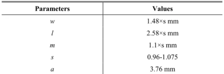
The detailed geometrical parameters associated with Fig. 1c are provided in Table I. The unit-cell periodicity equals 0.36λ0 (3.76 mm),
where λ0 is the wavelength in the free-space at 29 GHz. As shown in
Fig. 2, the polarizations between the receiving and transmitting layers are orthogonal, with the main direction of the E-field vector lying in the =135°- and =45°-direction in the xOy plane, respectively. A 1-bit phase resolution (i.e. 2 phase states with 180° of relative phase-shift) is obtained by rotating by 180° either the receiving layer or the transmitting one with respect to their original orientation. Moreover, to further enhance the phase resolution – or equivalently to increase the TA gain and efficiency for a given lattice size and number of unit-cells –, the patch dimensions are scaled by a factor s, as indicated in Table I. Therefore, by combining a set of N given values of s together with the 180° rotation technique, it is possible to reach a set of unit-cells with 2N different phase states.
The frequency responses computed for four values (N = 4) of s (0.96, 1, 1.04 and 1.075) are represented in Figs. 2a and 2b in phase and amplitude, respectively, for the Ka-band Satcom civil and military frequencies (27.5 to 31 GHz). These values have been selected to obtain a total phase variation of 315° with a phase step of 45° between two consecutive phase states. Note that the phase curves plotted in Fig. 2a are almost parallels. The unit-cell with s = 1.0 exhibits insertion loss lower than 0.5 dB at 29 GHz and a -1-dB transmission bandwidth of 3 GHz (27.7-30.7 GHz), equivalent to 10.3% around 29 GHz for phase states 0° and 180°. Scaling the patch dimensions by varying the value of s allows tuning the center frequency of the unit-cell, as clearly demonstrated by the unit-cell bandpass responses represented in Fig. 2b. Although the total useful bandwidth of the unit-cells is reduced due to the increased transmission loss away from the central frequency, this phenomenon is not critical at the TA level for two main reasons: first, the use of 3-bit unit-cells allows to reduce the phase quantization loss around 3 dB (as compared to 1-bit unit-cells); second, the total power radiated by the TA can be maximized by the proper choice of the unit-cell type located at the TA center.
TABLEI
UNIT-CELL GEOMETRICAL PARAMETERS
Parameters Values w 1.48×s mm l 2.58×s mm m 1.1×s mm s 0.96-1.075 a 3.76 mm
III. DUAL-CIRCULARLY-POLARIZED TRANSMITARRAYS
The unit-cell described in Section II is used to design several transmitarray prototypes. To achieve dual-CP, each dual-LP TA panel is covered by the same polarizer so as to operate in dual-CP, and is made of two interleaved TA sub-arrays linearly polarized at =45° and =135°. These polarizations are denoted by D1 and D2 respectively, where D stands for diagonal polarization. The corresponding interleaving technique has been described in [15], and the polarizer performance is available in [16].
(a)
(b)
Fig. 2. Transmission coefficients computed at Ka-band for the single-polarized unit-cells (Fig. 1b): (a) phase response, (b) magnitude response. The dotted lines are obtained by applying the 180°-rotation technique to the four unit-cells with their associated scaling parameter (s) in different colors.
A. Transmitarray Design and Prototypes
Square transmitarrays based on the proposed unit-cell have been designed, fabricated, and characterized. The sub-transmitarrays contain 52-by-52 and 53-by-53 unit-cells operating in 45°- and 135°-linear polarization, respectively; the aperture length side is 19.26×λ0
(i.e. 199.2 cm). They are interleaved to create dual-LP transmitarray, as illustrated in Fig. 3. Each transmitarray layout has been designed at 29 GHz. It is illuminated by a linearly-polarized standard gain horn (ATM 34-440-6) placed at a distance of 134 mm from the TA panel (this corresponds to F/D = 0.66 and an edge taper illumination of
27.5 28 28.5 29 29.5 30 30.5 31 -180 -135 -90 -45 0 45 90 135 180 Frequency (GHz) T ra ns m is si on P ha se (°) s = 0.96 s = 1.0 s = 1.04 s = 1.075 27.5 28 28.5 29 29.5 30 30.5 31 -12 -9 -6 -3 -2 -1 0 Frequency (GHz) T ra ns m is si on Ma gn itu de ( dB ) s = 0.96 s = 1.0 s = 1.04 s = 1.075
ACCEPTED MANUSCRIPT
about 9 dB). The same value of F/D has been used for all prototypes. The focal distance and the phase distribution have been optimized using our analytical tool previously validated up to 60 GHz [15], [17]-[19].
Fig. 3. Top view of radiation side of a dual-LP transmitarray made of two interleaved 52-by-52 (in solid color pattern) and 53-by-53 sub-arrays (in non-filled pattern) in D1 and D2 polarization, respectively.
(a) Prototype I: D1 to RHCP (b) Prototype I: D2 to LHCP
(c) Prototype II: D1 to RHCP (d) Prototype II: D2 to LHCP
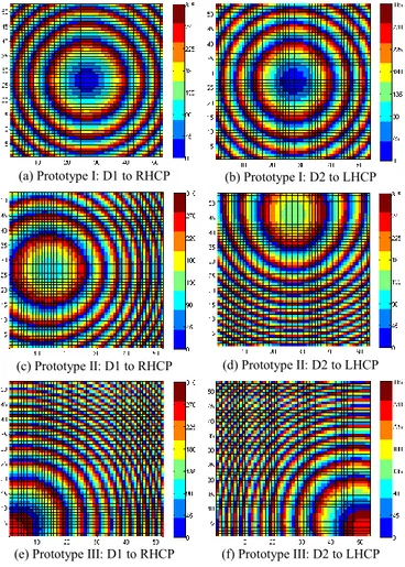
(e) Prototype III: D1 to RHCP (f) Prototype III: D2 to LHCP Fig. 4. Phase distribution across transmitarray aperture for D1 and D2 arrays. (a-b) Prototype I. (c-d) Prototype II. (e-f). Prototype III. D1 and D2 stand for 45°- and 135°-polarizations, respectively.
Three TA prototypes have been fabricated. They are listed in Table II. The first one (Prototype I) points at boresight for both polarizations (either linear or circular ones), whereas, for the second one (Prototype II), the beams associated to both polarizations point in two different directions (-20° or +30°). Finally, the third one (Prototype III) radiates
two offset extreme beams (±50°); this configuration allows testing the antenna performance limitations far away from boresight.
The phase distributions across the radiating aperture are represented in Fig. 4 for each prototype, whereas, Fig. 5 shows Prototype I with its mechanical support. The transmitarray size is 220 mm×220 mm×1.2 mm (including 10-mm-width of -edges for fixture) while polarizer is much larger (403 mm×250 mm×12 mm, [16]) as shown in Fig. 5b.
TABLEII
PROTOTYPES AND THEIR BEAM DIRECTIONS
Prototype Beam direction (Φ, θ), scanning plane
D1 to RHCP D2 to LHCP
Prototype I (0°,0°), Broadside (0°,0°), Broadside
Prototype II (0°,-20°) (90°,30°)
Prototype III (45°,-50°) (-45°,50°)
(a)
(b)
Fig. 5. Transmitarray antenna (Prototype I) mounted in IETR anechoic chamber (a) without and (b) with polarizer close to the surface.
ACCEPTED MANUSCRIPT
Due to their very large size, the performance of the TA prototypes cannot be computed using full-wave simulations. Instead we use here our in-house code [11], [17]-[19] to determine their radiation performance (efficiency and gain). Table III compares the main features of the 1-bit (s = 1.0) and 3-bit (s = 0.96, 1, 1.04 and 1.075) TAs operating in polarization D1, for prototype I in RHCP. In both cases, the TAs are illuminated with a 11.5-dBi horn; this leads to a 1.1-dB spillover loss for F/D = 0.66. As expected the aperture efficiency and gain of the 3-bit TA are improved by increasing the phase resolution, but its BW is slightly reduced as compared to 1-bit one due to the bandpass response of the unit-cells (see Fig. 2b).
TABLEIII
EFFICIENCY AND BANDWIDTH OF 1-BIT AND 3-BIT LINEARLY-POLARIZED
TRANSMITARRAY ANTENNAS AT 29GHZ
Phase resolution 1-bit 3-bit
Insertion loss (dB) 0.3 0.8 TA gain (dBi) 30.1 31.8 Aperture efficiency 23 % 34 % 1-dB bandwidth 28.3-31.2 GHz (10%) 28.4-30.5 GHz (7.0 %) 3-dB bandwidth 27.7-31.8 GHz (14.1 %) 27.8-31.6 GHz (13.1%) B. Experimental Results
In these experiments, a single-LP horn is used in each polarization and is rotated by 90° to generate the orthogonal polarization. The conversion from LP to CP will generate either RHCP or LHCP for each horn polarization. The co- and cross-polarizations for all prototypes are defined in Table IV.
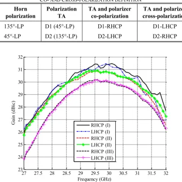
TABLEIV
CO- AND CROSS-POLARIZATION DEFINITION
Horn polarization Polarization TA TA and polarizer co-polarization TA and polarizer cross-polarization 135°-LP D1 (45°-LP) D1-RHCP D1-LHCP 45°-LP D2 (135°-LP) D2-LHCP D2-RHCP
Fig. 6. Measured maximum co-polarized gains of the three prototypes with respect to frequency at Ka-band.
The radiation properties of the three prototypes have been measured in the millimeter-wave anechoic chamber of IETR, in the far field zone, both in linear and circular polarizations (Fig. 5). As explained above, a polarizer is added in front of the transmitarray
(radiation side) to convert the outgoing dual-LP wave into dual-CP one. Prototype I with the polarizer is shown in Fig. 5b. The polarizer, previously reported in [16], has an axial ratio (AR) lower than 1 dB from 26.5 GHz to 28.5 GHz, but exhibits a slightly higher AR (2.3 dB) at 29 GHz. When the polarizer is present, polarizations D1 and D2 are converted into RHCP and LHCP, respectively.
The distance between the dual-LP transmitarray and the polarizer has been selected to minimize the AR value (0.8 dB) at 29 GHz.
Fig. 7. Measured co-polarization radiation patterns normalized to the peak gain of each prototype at 29 GHz.
The gain frequency response is plotted in Fig. 6 for all prototypes. The measured 1-dB gain bandwidth (BW) is larger than 2.2 GHz (or equivalently 7.6 %) around 29 GHz, while the calculated and measured 3-dB gain BW covers the whole Satcom Ka-band for all prototypes and for each polarization. The maximum gains of prototype I equal 31.4 dBi with aperture efficiencies higher 36.6 % at 29.5 and 29.9 GHz respectively in both CPs (see Fig. 6). The gain curves between RHCP and LHCP are almost superimposed for all prototypes, especially for beams offset 50° (prototype III); this demonstrates the independence of both CP polarizations.
The normalized radiation patterns measured at 29 GHz are plotted in Fig. 7. The main beam quality is good, with side lobe levels lower than -20dB below the maximum. The measured cross-polarization discrimination (XPD), not shown for brevity purposes, remains below -14.5 dB for beams at boresight and at -20° (AR < 2.9 dB) while the XPD level for beams pointing at ± 50° is lower than -22.5 dB (AR < 1.5 dB). The AR ratio is also lower than 3 dB from 27 GHz to 30 GHz, for prototypes I and II, and from 27.7 GHz to 29.8 GHz for prototype III, respectively. Its value exceeds 3 dB above 29.8 GHz since the center frequency of the polarizer (27.2 GHz, [16]) is slightly different from the design frequency of the TAs (29 GHz). The scanning loss of the main beam pointing at extreme angles (± 50°, Prototype III) is about 1 dB (see Fig. 6 and 7) as compared to the maximum gain at boresight (Prototype I). Table V summarizes the main properties of the proposed TA in comparison with others in terms of radiation characteristics in CP at Ka-band.
TABLEV
PASSIVE TRANSMITARRAY PROTOTYPES IN DUAL-CP AT KA-BAND.
Ref., type Freq.
(GHz) -3-dB BW (GHz) XPD (dB) AR (dB) This work 29 2.2 (7.6 %) -14.5 2.9 [14], TA 20 - < -11 - [14], TA 30 - < -7.5 - 27 27.5 28 28.5 29 29.5 30 30.5 31 31.5 32 23 24 25 26 27 28 29 30 31 32 Frequency (GHz) G ai n (d Bi c) RHCP (I) LHCP (I) RHCP (II) LHCP (II) RHCP (III) LHCP (III) -80 -70 -60 -50 -40 -30 -20 -10 0 10 20 30 40 50 60 70 80 -50 -40 -30 -20 -10 0 theta (°) N orm al iz ed Ra di at io n Pa tte rn (d B) D1-RHCP (I) D2-LHCP (I) D1-RHCP (II) D2-LHCP (II) D1-RHCP (III) D2-LHCP (III)
ACCEPTED MANUSCRIPT
[7], RA 8.37 790 (9.4 %) < 12 3.5
IV. CONCLUSION
Dual-CP transmitarray antennas with independent radiation performance in each polarization have been reported here at Ka-band. The TA architecture is based on a dual-LP interleaved transmitarray combined with an add-on polarization converter. Various experimental results have been presented using large-size TAs (5513 unit-cells in total).
Very good agreement has been obtained between calculation and measurement in linear polarization across the whole frequency band from 27 GHz to 32 GHz. Although higher axial ratio values are recorded beyond 29 GHz due to the limited polarizer bandwidth in the band of interest, excellent polarization quality has been demonstrated below 29.5 GHz, even for main beam direction pointing up to 50°.
ACKNOWLEDGMENT
This work has been partly supported by the European Union through the European Regional Development Fund (ERDF), and also by Ministry of Higher Education and Research, Brittany and Rennes Métropole, through the CPER Project SOPHIE/STIC & Ondes.
REFERENCES
[1] R. Pearson, “Next generation mobile SATCOM terminal antennas for a transformed world,” 5th European Conf. Antennas and Propagation,
Rome, Italy, Mar. 11-15, 2011.
[2] R. Florencio, J. A. Encinar, R. R. Boix, and G. Perez-Palomino, “Dual-polarisation reflectarray made of cells with two orthogonal sets of parallel dipoles for bandwidth and cross-polarisation improvement,” IET Microw., Antennas Propag. , vol. 8, no. 15, pp. 1389–1397, 2014. [3] Q. Wang, Z. Shao, P. Li, L. Li, and Y. Cheng, “A dual polarization,
broad-band, millimeter-wave reflectarray using modified cross loop element,” Microw. Opt. Technol. Lett., vol. 56, no. 2, pp. 287–293, 2014. [4] R. Pereira, R. Gillard, R. Sauleau, P. Potier, T. Dousset, and X. Delestre, “Four-state dual polarisation unit-cells for reflectarray applications,” Electron. Lett. , vol. 46, no. 11, pp. 742–743, May 2010.
[5] M. R. Chaharmir, J. Shaker, N. Gagnon, and D. Lee, “Design of broadband, single layer dual-band large reflectarray using multi open loop elements,” IEEE Trans. Antennas Propag., vol. 58, no. 9, pp. 2875– 2883, Sep. 2010.
[6] M. A. Joyal, R. E. Hani, M. Riel, Y. Demers, and J. J. Laurin, “A reflectarray-based dual-surface reflector working in circular polarization,” IEEE Trans. Antennas Propag., vol. 63, no. 4, pp. 1306– 1313, Apr. 2015.
[7] S. Mener, R. Gillard, R. Sauleau, A. Bellion, and P. Potier, “Dual circularly polarized reflectarray with independent control of polarizations,” IEEE Trans. Antennas Propag., vol. 63, no. 4, pp. 1877– 1881, Apr. 2015.
[8] C. Huang, W. Pan, X. Ma, B. Zhao, J. Cui and X. Luo, “Using reconfigurable transmitarray to achieve beam-steering and polarization manipulation applications,” IEEE Trans. Antennas Propag., vol. 63, no. 11, pp. 4801–4810, Nov. 2015.
[9] W. Pan, C. Huang, X. Ma, B. Jiang, and X. Luo, “A dual linearly polarized transmitarray element with 1-bit phase resolution in X-band,” IEEE Antennas Wireless Propag. Lett., vol. 14, pp. 167–170, 2015. [10] L. Di Palma, A. Clemente, L. Dussopt, R. Sauleau, P. Potier, and P.
Pouliguen, “Circularly-polarized reconfigurable transmitarray in Ka-band with beam scanning and polarization switching capabilities," IEEE Trans. Antennas Propag., vol. 65, no. 2, pp. 529–540, Feb. 2017. [11] K. Pham, N. T. Nguyen, A. Clemente, L. Di Palma, L. Le Coq, L.
Dussopt, and R. Sauleau, “Design of wideband dual linearly-polarized transmitarray antennas,” IEEE Trans. Antennas Propag., vol. 64, no. 5, pp. 2022–2026, May 2016.
[12] M. O. Bagheri, H. R. Hassani, and B. Rahmati, “Dual-band, dual-polarised metallic slot transmitarray antenna,” IET Microw., Antennas Propag., vol. 11, no. 3, pp. 402–409, Apr. 2017.
[13] L. Chen, Y. Ge and T. S. Bird, “Ultrathin flat microwave transmitarray antenna for dual-polarised operations,” Electron. Lett., vol. 52, no. 20, pp. 1653-1654, 29 9 2016.
[14] P. Naseri, S. A. Matos, J. R. Costa, C. A. Fernandes, and N J. G. Fonseca, “Dual-band dual linear to circular polarization converter in transmission mode-application to K/Ka-band satellite communications,” IEEE Trans. Antennas Propag., vol. 66, no. 12, pp. 7128-7137, Dec 2018.
[15] K. Pham, R. Sauleau, E. Fourn, F. Diaby, A. Clemente, and L. Dussopt, “Dual-band transmitarrays with dual-linear polarization at Ka-band,” IEEE Trans. Antennas Propag., vol. 65, no. 12, pp. 7009–7018, Dec. 2017.
[16] D. Blanco and R. Sauleau, “Broadband and broad-angle multilayer polarizer based on hybrid optimization algorithm for low-cost Ka-band applications,” IEEE Trans. Antennas Propag., vol. 66, no. 4, pp. 1874– 1881, Apr. 2018.
[17] F. Diaby, A. Clemente, K. Pham, R. Sauleau, and L. Dussopt, “Circularly-polarized transmitarray antennas at Ka-band,” IEEE Antennas Wireless Propag. Lett., vol. 17, no. 7, pp. 1204-1208, Jul. 2018. [18] K. T. Pham, A. Clemente, E. Fourn, F. Diaby, L. Dussopt, and R. Sauleau, “Low-cost metal-only transmitarray antennas at Ka-Band,” IEEE Antennas Wireless Propag. Lett., vol. 18, no. 6, pp. 1243-1247, Jun. 2019.
[19] L. Dussopt A. Moknache, J. Sailly, A. Lamminen, M. Kaunisto, J. Aurinsalo, T. Bateman, and J. Francey, “A V-band switched-beam linearly polarized transmit-array antenna for wireless backhaul applications,” IEEE Trans. Antennas Propag., vol. 65, no. 12, pp. 6788-6793, Dec. 2017.