HAL Id: hal-01714873
https://hal.archives-ouvertes.fr/hal-01714873
Submitted on 23 Feb 2018HAL is a multi-disciplinary open access archive for the deposit and dissemination of sci-entific research documents, whether they are pub-lished or not. The documents may come from teaching and research institutions in France or abroad, or from public or private research centers.
L’archive ouverte pluridisciplinaire HAL, est destinée au dépôt et à la diffusion de documents scientifiques de niveau recherche, publiés ou non, émanant des établissements d’enseignement et de recherche français ou étrangers, des laboratoires publics ou privés.
Toward an hybrid control architecture for a mobile
multi-robot systems
Ahmed Benzerrouk, Lounis Adouane, Philippe Martinet, Nicolas Andreff
To cite this version:
Ahmed Benzerrouk, Lounis Adouane, Philippe Martinet, Nicolas Andreff. Toward an hybrid control architecture for a mobile multi-robot systems. 3rd National Conference on Control Architectures of Robots (CAR08), May 2008, Bourges, France. �hal-01714873�
T
OWARD AN HYBRID CONTROL ARCHITECTURE FOR A MOBILE MULTI-
ROBOT SYSTEMSAhmed Benzerrouk, Lounis Adouane, Philippe Martinet, Nicolas Andreff
ahmed.benzerrouk@lasmea.univ-bpclermont.fr LASMEA – UMR CNRS 6602
24, avenue des landais 63177 Aubière, France.
Abstract
Hybrid architecture for autonomous navigation robots is presented in this paper. The principal future aim of this architecture is to achieve multi-robot convoy which must navigate in urban background, where autonomous vehicles have to track the desired trajectory while avoiding possible obstacles (walkers, other robots, etc.). Currently, we consider only the case of fixed obstacles. We propose to coordinate two continuous controllers (trajectory tracking and obstacle avoidance) by discrete events. However, hard switch from obstacle avoidance to trajectory following controller, may cause collision or undesired effects due to nonholonomic constraint or switching effects. Therefore, we introduce a third controller to overcome these drawbacks.
Keywords
Mobile robots control, Hybrid architecture, Lyapunov stability.
1
Introduction
Controlling a nonholonomic mobile robot to follow a desired trajectory is treated since a long time (see [12], [5] for instance) and is still current as the case of trajectory tracking with sliding [11]. If controllers [4] were developed to solve it, the environment of robots navigation is subject to a lot of variations. Indeed, it’s obvious that these controllers become easily useless and lead to collision when an obstacle appears on the robot’s way since they were only designed to track trajectory.
However, the obstacle avoidance is not a problem anymore since it is widely investigated in the literature: Khatib [9] used the potential fields to give a real time method adapted to the obstacle avoidance problem. He assumes that the robot moves in a potential field considering the objective to reach as an attractive point whereas the obstacle surfaces are repulsive fields. Since the robot’s action is accomplished by the sum of individual gradients at the robot’s location, this method suffers from the local minima problem when for instance, this sum is null. To overcome this undesirable situation, circular potential fields were used in the direction of avoidance [14], [7]. However, Kim and al [10] say that these fields type cannot adjust how far the robot avoids the obstacle and propose the limit cycle navigation as a new method. Zapata and al [16] use a virtual deformable zone (DVZ) surrounding the robot thanks to proximity sensors: if an obstacle is detected, it will deform the DVZ and the approach is to minimize this deformation by modifying the control vector.
The unknown nature of the robot’s environment in the most of cases, leads up to develop control architectures which guarantee a desired and mostly a safe navigation for the
3 National Conference on “Control Architectures of Robots” Bourges, May 29-30, 2008 robot. In fact, the intuitive idea to make a mobile robot able to avoid obstacles while tracking the desired trajectory is to have two simple controllers and to switch from one to another according to the robot’s relative position to the obstacle (figure 1). It forms what we call hybrid systems where discrete events allow switching between continuous behaviours.
However, Branicky, in [2], shows that random switches between two stable systems lead easily to instability of the control. He consequently imposes restrictions on switching to guarantee a global stability which has been proven via multiple Lyapunov functions [2]. Moreover, hard switches may lead to the Zeno phenomenon [8] that exhibits an infinite number of discrete transitions between controllers in finite time. In robotics, it potentially appears when the robot is on the boundary where the discrete event becomes true causing switch between nodes which represent individual controllers. Chattering effects caused by this phenomenon were shown by Egerstedt [6]. Adouane in [1], proposes to avoid this hard chattering between controllers’ commands while introducing a specific adaptation of each controller law. In [6] Egerstedt regularizes its automaton by adding a node to overcome these undesirable effects: this node contains the sliding dynamics that is defined on the boundary between the two controllers.
In the proposed paper, we apply an hybrid architecture for autonomous mobile robot using mainly two classical behaviours for an autonomous mobile robot: trajectory tracking and obstacle avoidance. We propose to guarantee restrictions on switching via multiple Lyapunov functions by introducing an other controller which leads the robot on its trajectory after the obstacle avoidance step. Simulation shows that our proposition insures global stability for the robot control.
The rest of this paper is organized as follows. In section 2, we give the proposed control architecture and give some details on the multiple Lyapunov function. Stability of individual controllers is studied in section 3. Simulation results are presented in section 4. We conclude and give some prospects in section 5.
2
Architecture of control
The proposed hybrid architecture is supposed to be applied to a mobile robot using basic perceptual and decisional capabilities. Therefore, according to the robot’s sensors information, decision to apply the convenient controller is made.
P E R C E P T I O N S Obstacle avoidance Trajectory tracking
FIG. 1 - Hybrid control architecture for trajectory tracking with obstacle avoidance
Command
Selection mechanism
However, as we saw in section 1, hard switches lead to instability or cause chattering effects even if each controller is individually stable. Therefore, more restrictions are needed to control these switches.
Multiple Lyapunov function method [2] gives sufficient conditions to guarantee stability of the overall system. Based on this method, the following theorem which has been demonstrated in [2] will be used.
Theorem
Given N dynamical systems, Σ1, …, ΣN, each with equilibrium point at the origin, and
N candidate Lyapunov functions, V1, …, VN.
If {Vi decreases when Σi is active} and
{Vi (at the time when Σi switched in) ≤ Vi (at the last time when Σi switched in)}
Then the hybrid system is Lyapunov stable (figure 2).
In our case, it is possible to use this theorem to guarantee stability of the robot during all its navigation. Since we use controllers that stability is proven by the simple Lyapunov theorem, we have only the second condition of the above method to satisfy. Moreover, we have to satisfy this condition for the trajectory tracking only. Indeed, obstacles that the robot meets are independents, and the obstacle avoidance controller is normally activated only one time for each obstacle. Therefore, our idea is to use a specific “go-to-goal” controller (cf. subsection 3.4). This one is stable and is activated once the obstacle is avoided. Its role is to lead the robot toward the reference trajectory until the Lyapunov function of the trajectory tracking controller becomes less than the last time this one is switched in. The proposed control architecture is given in figure 3.
Time V
FIG.2 – Variation of the Lyapunov function for the “i” controller. Solid lines indicate that i is active, dashed inactive.
Vt0
t0 t1
3 National Conference on “Control Architectures of Robots” Bourges, May 29-30, 2008
2.1 The proposed control structure
Figure 4 shows the possible undesired robot behaviours according to the robot position. This is due to inappropriate switches between obstacle avoidance controller and the trajectory tracking one. This is what motivate us to search for a regularized automaton that insures safety and stable navigation to the robot.
On the left, switching occurs soon enough. Therefore, converging to the trajectory lead the robot to the obstacle zone which activates the obstacle avoidance controller again and so forth. On the right, the undesired effects are due to the nonholonomic constraint. Indeed, switching to trajectory tracking occurs only when the robot is on (or too close) to the reference trajectory.
Figure 5 shows an automaton where switch transitions are only guided by geometric conditions overlooking other constraints. Note that Drobot-obstacle is the Euclidian distance
between the obstacle center and the axle center of the robot and Rv is the obstacle radius plus a
safety distance δ considering the robot dimension and a safety margin. P E R C E P T I O N S Obstacle avoidance Go-to-goal Trajectory tracking
FIG. 3 – The proposed hybrid architecture of control
Mobile robot Selection mechanism Command Y Y X vr X Reference trajectory Obstacle detection area
FIG.4 - Possible consequences of hard switches from obstacle avoidance to trajectory tracking. Dash lines show the undesired resulted robot behaviour.
δ
+ = − + − = − obstacle v obstacle robot obstacle robot obstacle robot R R y y x x D ( )² ( )²To avoid this, we introduce the “go-to-goal” controller to regularize hard switches due to the only distance criterion (figure 6). This controller leads the robot to a virtual target that we define on the reference trajectory which keep it away from the risk of oscillation zone (cf. figure 7). Drobot-obstacle > Rv Drobot-obstacle ≤ Rv Trajectory tracking Obstacle avoidance
FIG. 5 - Hard switches automaton.
no detected obstacle Obstacle passed Virtual target reached Trajectory tracking Go-to-goal Obstacle avoidance Drobot-obstacle ≤ Rv
FIG. 6 – The proposed automaton with an extra node corresponding to the go-to-goal controller
The obstacle is not passed virtual target is not reached no detected obstacle An other obstacle is detected the obstacle is not passed
3 National Conference on “Control Architectures of Robots” Bourges, May 29-30, 2008
The virtual target point “Pt” corresponds to the intersection of a circle of radius (Rv + ε)
where ε> 0. We define also Pe(xend, yend) as the end point where the obstacle is considered as
already avoided. It is also the intersection of the tangent of the detection zone (circle of radius Rv) passing by the virtual target.
The position Pe in the case where the robot avoids the obstacle clockwise can be
calculated by ) sin( ) cos( ) arctan( ) ² )² ( arctan( 2 1 2 1 arg arg 2 1
θ
θ
θ
θ
θ
ε
θ
+ + = + + = − − = − + = − − v obst end v obst end obst et t virtual obst et t virtual v v v R y y R x x x x y y R R RNote: The choice of the way of avoidance (clockwise or counter-clockwise) is indicated in subsection 3.3.
The second condition of the multiple Lyapunov function is then satisfied for trajectory tracking controller by leading the robot on the virtual target once the obstacle is avoided. Indeed, the chosen Lyapunov function (subsection 3.2) depends on the lateral and angular errors. Since we can correct the robot position and heading by go-to-goal controller once the obstacle is avoided and the virtual target is reached. Therefore, we minimize this Lyapunov function (figure 8) before switching in trajectory tracking controller again.
Y Reference trajectory Obstacle detection zone
y
virtual-targety
obst O Rv+ε Rv Xx
obstx
virtual-targetFIG 7 - Virtual target to reach before reactivating trajectory tracking controller. The obstacle is avoided here clockwise.
θ2 θ1 Virtual target
x
endy
end Pt Pe3
Mobile robot control
3.1
Robot model
Consider the unicycle mobile robot (figure 9). Let x, y and θ be the state variables where x ∈ IR and y ∈ IR are the Cartesian coordinates, θ ∈ ]-π, π] is the robot’s orientation with respect to the X-axis. We note respectively v and u the linear and the angular velocity of the robot. The kinematics model of the robot can be described by
u v y v x = = =
θ
θ
θ
& & & ) sin( . ) cos( .3.2 Trajectory tracking controller
Considering the lateral and the angular errors of the robot (figure 10):
c c traj c traj x y y x e
θ
θ
θ
θ
θ
− = − − − = ~ cos ). ( sin ). ( Time VFIG.8 – Evolution of the Lyapunov function of trajectory tracking when go-to-goal controller is active. Continuous line means that trajectory tracking is active.
Go to goal Controller active y x Y X θ v
3 National Conference on “Control Architectures of Robots” Bourges, May 29-30, 2008 Where (xtraj,ytraj) are the coordinates of the set points of the reference trajectory, and
θ
cis the corresponding desired orientation. Tracking a reference trajectory means that e andθ
~ must tend towards 0. If we take v = constant, the time-variation of these states are given byu v e = =
θ
θ
& & ~ sin .The following controller based on the Lyapunov stability is developed in [3] and is given by
θ
θ
θ
~
.
.
)
~
~
sin
.(
.
.
2 1v
e
k
v
k
u
K
v
−
−
=
=
Where K, k1, k2 are constants.
To prove the stability of this controller, we take V=
2 ² ~ 2 ² . 1
θ
+ e k as a candidate Lyapunov function. Its time derivative is V =−k2.v.θ
~²& ≤ 0. Then, we can conclude that the controller is stable.
3.3 Obstacle avoidance controller
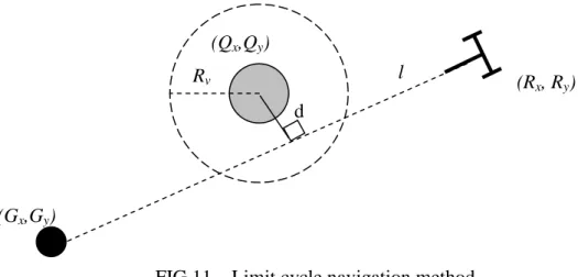
We saw in section 1, that the limit cycle navigation method seems overcome the drawbacks of the other obstacle avoidance methods. Moreover, it allows deciding in which direction and how far the robot avoids the obstacle. We reintroduce briefly the limit cycle navigation algorithm proposed in [10] that we use in the avoidance obstacle controller. Consider a mobile robot which must reach the target whose global coordinates are (Gx, Gy)
while avoiding the circular obstacle of global coordinates (Qx, Qy) and a radius Rv
(corresponding to the real radius of the obstacle plus a distance including the robot size and a safe margin) (figure 11).
θ
~ θ y ytraj e x xtraj Y X θc vThe steps of the limit-cycle method are as follows:
The line l has a.x+b.y+c = 0 as equation.
1) The distance d from the center of the obstacle to the line l is calculated as
² ² . . b a c Q b Q a d x y + + + = .
2) The desired direction of the robot is calculated at each position by
²) ² ² ( ²) ² ² ( y x R y x d d y y x R x y d d x v v − − + − = − − + = & &
Where x and y are relative values of the robot position according to the obstacle. In these equations, if d is positive, the robot avoids the obstacle clockwise. Otherwise, it is avoided in a counter-clockwise direction.
To prove stability along the trajectory, the Lyapunov function candidate is given by V = x²+ y² y
y x x
V& =2 &+2 & = 2V(x)(rv²-V(x))
Which is negative for V(x)>rv². Therefore, we can adjust the radius and consequently control
the distance that the robot keeps with respect to the obstacle.
3.4 Go-to-goal controller
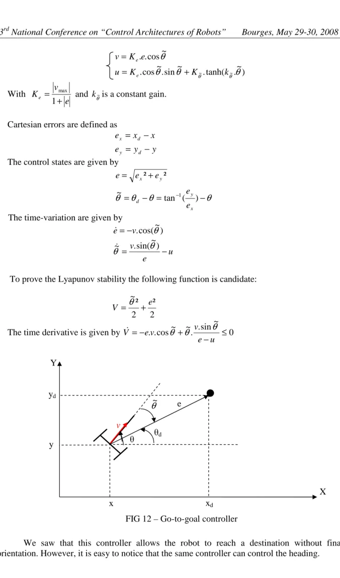
The task to accomplish by the robot is simply to reach a desired position(xd,yd). It means that (e,
θ
~) must tends to (0, 0) (figure 12).Developed in [13], the following controller allows the robot to reach a desired position without guaranteeing the orientation:
(Gx,Gy) (Rx, Ry) (Qx,Qy) l Rv d
3 National Conference on “Control Architectures of Robots” Bourges, May 29-30, 2008 ) ~ . tanh( . ~ sin . ~ cos . ~ cos . . ~ ~
θ
θ
θ
θ
θ θ k K K u e K v e e + = = With e v Ke + = 1 maxand k is a constant gain. θ~
Cartesian errors are defined as y y e x x e d y d x − = − = The control states are given by
θ
θ
θ
θ
= − = − + = − ) ( tan ~ ² ² 1 x y d y x e e e e eThe time-variation are given by u e v v e − = − = ) ~ sin( . ~ ) ~ cos( .
θ
θ
θ
& &To prove the Lyapunov stability the following function is candidate:
2 ² 2 ² ~ e V =
θ
+The time derivative is given by 0
~ sin . . ~ ~ cos . . ≤ − + − = u e v v e V&
θ
θ
θ
We saw that this controller allows the robot to reach a destination without final orientation. However, it is easy to notice that the same controller can control the heading.
y x yd xd e θd Y X θ v
θ
~Indeed, when v = 0, the controller is still stable and only u controls the desired heading. Stability when switching to v = 0 in order to control final heading is immediate since the same Lyapunov function is kept. Detailed proof is available in [15].
4
Simulation
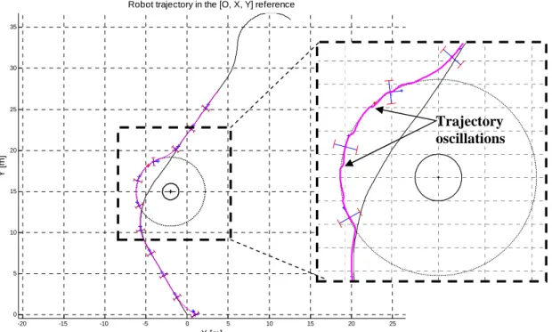
To estimate the relevance of the proposed hybrid architecture, we compare it with results given by hard switches between the two controllers: trajectory tracking and obstacle avoidance. Indeed, we use MATLAB to simulate a mobile robot tracking a given trajectory while avoiding an obstacle. The real path the robot follows with hard switches is given in figure 13.
We can see that when detecting the obstacle, the robot switches effectively to obstacle avoidance controller. However, the distance separating the robot from the obstacle is the only condition of switching. Therefore, oscillation in the robot’s path is observed. It is due to switching to trajectory tracking as soon as Drobot-obstacle is higher than Rv which is the detection
zone radius. While the obstacle is not passed, the robot (which is now controlled by trajectory tracking command) falls in the detection zone again and tries to avoid it again (switch to obstacle avoidance controller).
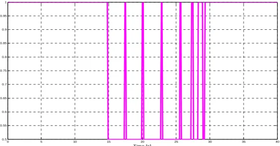
Switch moments are illustrated in figure 14 which shows clearly undesirable switching to trajectory controllers whereas the obstacle is not passed yet.
Moreover, figure 15 shows the Lyapunov function variation for the different controllers. In spite of decreasing when the controller is active, the second condition of the Multiple Lyapunov function theorem is not satisfied, and switching in the trajectory tracking occurs with a higher Luyapunov function value than the last switch in.
FIG 13 – Real robot’s path controlled by hard switches.
-20 -15 -10 -5 0 5 10 15 20 25 0 5 10 15 20 25 30 35
Robot trajectory in the [O, X, Y] reference
X [m] Y [ m ] Trajectory oscillations
3 National Conference on “Control Architectures of Robots” Bourges, May 29-30, 2008
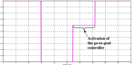
At the contrary, our architecture of control given in section 2 allows avoiding these useless switches since our automaton is regularized by the go-to-goal controller (figure 6). This latter prevents hard switches occurring before that the obstacle is passed. The real path followed by the robot is shown in figure 16 where no oscillation is observed.
Figure 16 shows clearly that our method prevents any undesired switch between controllers. Thereby, the robot does not switch to trajectory tracking before avoiding completely the obstacle. This is confirmed by switch moments (figure 17).
FIG 14 – Switching moments (high state corresponds to trajectory tracking controller whereas low state is for obstacle avoidance one).
0 5 10 15 20 25 30 35 40 0.5 0.55 0.6 0.65 0.7 0.75 0.8 0.85 0.9 0.95 1
Linear speed control (v)
Time [s]
FIG. 15 – Lyapunov variation functions with hard switches.
0 5 10 15 20 25 30 35 40 0 1 2 3 4 5 6 7 8 9 10 Time [s] V
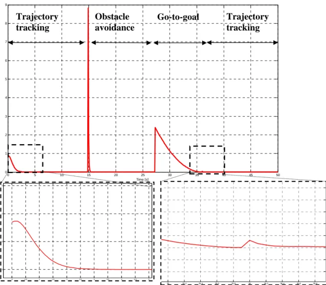
Figure 18 shows also that our method allows to satisfy the second condition of the Lyapunov variation function (cf. section 2). Indeed, when trajectory tracking is reactivated, its Lyapunov function value is less than the last time it switches in.
FIG 16 – Real robot path when controlled with the proposed control architecture -20 -15 -10 -5 0 5 10 15 20 25 0 5 10 15 20 25 30 35
Robot trajectory in the [O, X, Y] reference
X [m] Y [ m ] -6 -5 -4 -3 -2 -1 0 1 2
FIG 17 – Switch moments. High state corresponds to trajectory tracking controller. Low state is when the obstacle avoidance is active.
0 5 10 15 20 25 30 35 40 45 50 0.5 0.55 0.6 0.65 0.7 0.75 0.8 0.85 0.9 0.95 1
Linear speed control (v)
Time [s]
Activation of the go-to-goal controller
3 National Conference on “Control Architectures of Robots” Bourges, May 29-30, 2008 0 5 10 15 20 25 30 35 40 45 50 0 1 2 3 4 5 6 7 8 9 Time [s] 0 0.5 1 1.5 2 2.5 3 3.5 4 4.5 5 0 0.5 1 1.5 35 35.2 35.4 35.6 35.8 36 36.2 36.4 36.6 36.8
5
Conclusion and future works
We applied hybrid control architecture on a mobile robot to obtain a stable trajectory tracking while avoiding obstacles. Indeed, the robot is controlled by elementary continuous controllers according to the sub-tasks to accomplish (trajectory tracking, obstacle avoidance) and switching from a controller to an other is done referring to discrete events. We saw that hard switches cause chattering and are not efficient to insure a safe navigation. Therefore, we propose to use the multiple Lyapunov function for hybrid systems to design a stable hybrid control architecture. In addition to elementary stable controllers for the two main sub-tasks, we introduce a third controller which insures the second sufficient condition of multiple Lyapunov function (cf. section 2). Simulations show that our architecture prevents useless switches, guaranteeing thus a safe navigation for the robot. Applying this stable control architecture to a dynamic environment (e.g., moving obstacles), will be the subject of future works. Application to multi-robot systems navigating in formation seems also to be interesting. The objective is to make each robot able to avoid an obstacle before regaining the convoy.
FIG 18 - Lyapunov variation functions of the proposed control architecture. Trajectory tracking Obstacle avoidance Go-to-goal Trajectory tracking
References
[1] L. Adouane, “Adaptive Multi-Controller Architecture for the Navigation of Mobile Robot”, The 10th International Conference on Intelligent Autonomous Systems, Jul. 2008. [2] M. Branicky, “Multiple Lyapunov functions and other analysis tools for switched and hybrid systems”, IEEE Transactions on Automatic Control, vol. 43, pp 475-482, apr. 1998. [3] C. Canudas de Wit, B. Siciliano and G. Bastin, “Theory of Robot Control”, Springer Verlag Edition, ISBN 3540760547,pp 341-343, 1996.
[4] B. D’Andrea-Novel, G. Campion and G. Bastin, “Control of nonholonomic wheeled mobile robots by state feedback linearization”, International Journal of Robotics Research, pp. 543–559, Jun. 1995.
[5] A.W. Divelbiss, J.T. Wen, “Trajectory tracking control of a car-trailer system”, IEEE Transactions on Control Systems Technology, vol. 5, pp 269 – 278, May 1997.
[6] M. Egerstedt, X. Hu, “ A hybrid control approach to action coordination for mobile robots”, Automatica, vol. 38, pp 125-130, 2002.
[7] E. Gat, “Navigation templates: enhancements, extensions and experiments”, Proceedings of the IEEE International Conference on Robotics and Automation, pp. 541–547, 1993. [8] K. Johansson, M. Egerstedt, J. Lygeros and S. Sastry, “On the regularization of Zeno
hybrid automata”, Systems & Control Letters, Vol. 38, pp 141-150, Oct. 1999.
[9] O. Khatib, “Real-time obstacle avoidance for manipulators and mobile robots”, The International Journal of Robotics Research 5, pp. 90-99, 1986.
[10] D. Kim and J. Kim, “A real-time limit-cycle navigation method for fast mobile robots and its application to robot soccer”, Robotics and Autonomous Systems, vol. 42, pp. 17-30, Jan.2003.
[11] R. Lenain, B. Thuilot, C. Cariou, P. Martinet, “High accuracy path tracking for vehicles in presence of sliding: Application to farm vehicle automatic guidance for agricultural tasks”, Autonomous Robots, Kluwer Academic Publishers, vol. 21, pp. 79-97, Aug. 2006. [12] C. Samson, “Control of chained systems : application to path following and time-varying
point-stabilization” , IEEE Transactions on Automatic Control, vol. 40, pp 64–77, 1995.
[13] H. Secchi, R. Carelli and B. Mut, “Design of stable algorithms for mobile robots control with obstacle avoidance”, 14th IFAC World Congress, pp 185-190, 1999.
[14] M.G. Slack, “Navigation template: mediating qualitative guidance and quantitative control in mobile robots”, IEEE Transactions on Systems, Man and Cybernetics 23 , pp 452–466, 1993.
[15] J.M Toibero, R Carelli and B. Kuchen, “Switching control of mobile robots for autonomous navigation in unknown environments”, Robotics and Automation, IEEE International Conference on Robotics and Automation, pp 1974-1979, Apr. 2007.
[16] R. Zapata, P. Lepinay, “Reactive behaviors of fast mobile robots”, Journal of Robotics Systems, vol. 11, pp 13-20, 1994.


