HAL Id: hal-00908842
https://hal.inria.fr/hal-00908842
Preprint submitted on 18 May 2016
HAL is a multi-disciplinary open access
archive for the deposit and dissemination of
sci-entific research documents, whether they are
pub-lished or not. The documents may come from
teaching and research institutions in France or
abroad, or from public or private research centers.
L’archive ouverte pluridisciplinaire HAL, est
destinée au dépôt et à la diffusion de documents
scientifiques de niveau recherche, publiés ou non,
émanant des établissements d’enseignement et de
recherche français ou étrangers, des laboratoires
publics ou privés.
Seamless Coarse Grained Parallelism Integration in
Intensive Bioinformatics Workflows
Francois Moreews, Dominique Lavenier
To cite this version:
Francois Moreews, Dominique Lavenier. Seamless Coarse Grained Parallelism Integration in Intensive
Bioinformatics Workflows. 2016. �hal-00908842�
Seamless coarse grained parallelism integration in
intensive bioinformatics workflows
Francois Moreews
GENSCALE IRISA/INRA Rennes, France[email protected]
Dominique Lavenier
GENSCALE IRISA/INRIA Rennes, France[email protected]
ABSTRACT
To be easily constructed, shared and maintained, complex in silico bioinformatics analysis are structured as workflows. Furthermore, the growth of computational power and stor-age demand from this domain, requires workflows to be ef-ficiently executed. However, workflow performances usually rely on the ability of the designer to extract potential paral-lelism. But atomic bioinformatics tasks do not often exhibit direct parallelism which may appears later in the workflow design process.
In this paper, we propose a Model-Driven Architecture ap-proach for capturing the complete design process of bioinfor-matics workflows. More precisely, two workflow models are specified: the first one, called design model, graphically cap-tures a low throughput prototype. The second one, called execution model, specifies multiple levels of coarse grained parallelism. The execution model is automatically gener-ated from the design model using annotation derived from the EDAM ontology. These annotations describe the data types connecting differents elementary tasks. The execution model can then be interpreted by a workflow engine and executed on hardware having intensive computation facility.
1.
INTRODUCTION
Bioinformatics applications challenge today’s computation resources by raising the amount of data to process and com-putation requirement to a new level. As an illustration, many algorithms used for Next Generation Sequencing (NGS) data processing, like genome assembly or polymorphism dis-covery, are computationally intensive and have to deal with a huge amount of data.
The common answer to such challenge is to use large stor-age facilities associated with classical computer clusters that combine the processing power of multiples machines. A job scheduler is then in charge of dispatching the processing de-mand onto the available processing resources. Such architec-ture takes advantage of coarse grain parallelism to speed-up computation. This parallelism can either be used by
run-2013 Draft version. .
ning multiple applications in parallel or by designing the application in such way that it can be divided into smaller grain tasks. Even if more and more tools like mpiBlast [5] use distributed computational resources like cluster-nodes or CPU-cores, the data parallelism pattern often need to be manually coded. For this purpose, APIs that eases the im-plementation of coarse grain data parallelism patterns have been developped [4].
Bioinformatics analysis usually consists in writing a script calling heterogeneous specialized softwares provided by the research community. Such “pipelines” are usually described as a sequence of operations represented as a dataflow. In that case, applications are modeled as a network of opera-tions connected through their data dependencies. Such rep-resentations exploit the available parallelism by analyzing data dependencies between operations.
Workflow management systems (WMS) used in bioinfor-matics were often limited to educational or low throughput usage. With the development of middlewares designed to integrate the power of intensive computation infrastructure in client softwares, the orchestration of bioinformatics ser-vices deployed on a computation intensive production en-vironment became realistic [15]. Among these middlewares, the DRMAA API [2] standardizes the access to job shedulers and the Opal toolkit [11] wraps command lines and manages job posting through web services. Thus, nowadays, WMS that enable cluster or cloud job submissions have emerged as an interesting solution to face the high throughput se-quencing challenge.
Taverna [18] is a service oriented graphical workflow au-thoring and execution tool, able to orchestrate remote web services or local components. Associated with appropriate OPAL or PBS middleware clients embedded in actors, Tav-erna, but also Kepler [17], can be run on clusters. But many actors must be laboriously defined by the designer for a sin-gle intensive computation job execution (upload , submis-sion, wait, get result, download). The resulting graph rep-resentation contains many technical actor nodes that do not clearly display the main analysis steps.
In contrast, Galaxy [8] has been successfully adopted by the scientific community as a bioinformatics production en-vironment. Galaxy can integrate intensive computation tools and support a large collection of predefined bioinformatics components. It is used more as a tools repository where each task is independently manually launched than for its orches-tration capabilities. Galaxy has proved to be a solution for workflow prototyping using, for example, a conversion of the user activities as a “pipeline”. Galaxy workflow module, like
many dataflow based scientific WMS, proposes to ease the workflow specifications through a graph editing GUI and can schedule and run workflows, addressing clusters through job scheduler.
All these tools authorize the creation of atomic tasks, that internally manage parallelism. Thus, when available, coarse grain data parallelism is based on the implementation of each components. But these environments do not propose a way to integrate coarse grain data parallelism without hard coding or complex manipulations. They do not offer a gen-eral mechanism for data parallelism extraction.
In contrast, some generic grid computing oriented environ-ments like P-GRADE [7] offer a unified access to multiple complementary middlewares, each one dedicted to a level of parallelism extraction. The configuration of these tools is user-defined. Building highly intensive bioinformatics work-flow still relies on the technical ability of the designer to take advantage of the available data parallelism.
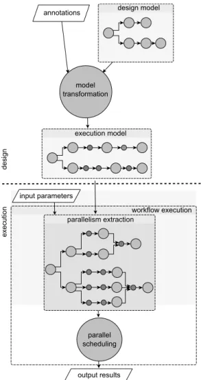
The purpose of this work is to greatly simplify the design process of bioinformatics workflows. Integrating a general mechanism of data parallelism extraction from a captured workflow prototype remains challenging. The goal is to hide to the designers (bioanalyst people) time consumming and error prone tasks dedicated to technical aspect of parallel implementation. This seamless parallelism integration could not only speed up the treatments but also facilitate the de-sign process and disseminate the usage of parallel workflows. To achieve this objective, we propose an approach based on a Model-Driven Architecture allowing the designer to eas-ily capture bioinformatics workflows using a high level model from which a parallel execution model is semi automatically derived. design model annotations model transformation output results workflow execution input parameters parallelism extraction execution model parallel scheduling de sig n exe cutio n
Figure 1: Overview of the workflow design and par-allel execution steps
Figure 1 illustrates the approach: the user first specifies a workflow using a graphical interface. He connects bioinfor-matics tools as a dataflow graph. The user is asked to inte-grate annotations for specifying data types flowing between nodes (bioinformatics tasks) of the graph. From this graph, and using a model transformation, an execution graph is generated from which parallelism can be automatically ex-tracted.
The rest of the paper is organized as follows: section 2 and 3 respectively present the workflow design model and the way the model is transformed. Section 4 describes the execution model. Section 5 discusses the integration of this Model-Driven approach in a new WMS dedicated to bioin-formatics intensive data treatment and gives directions for future works.
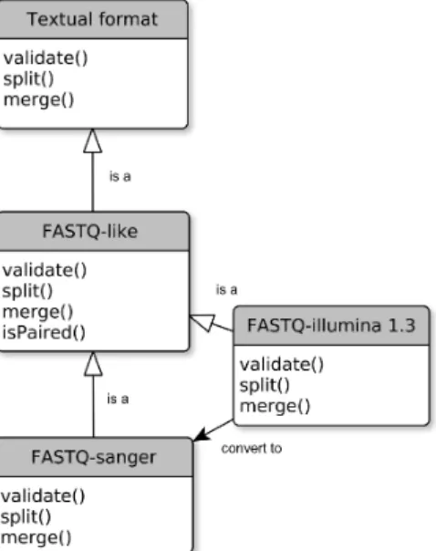
Figure 2: We use a data format hierarchy derived from EDAM ontology. Split and merge methods are implemented for each relevant data format.
2.
THE DESIGN MODEL
To initiate the design process, we defined a “design model” that eases the capture of a worfklow, omitting technical tasks such as paralellization.
The workflow design model is a simple dataflow graph where processes are the nodes and the data dependencies the edges of a direct acyclic graph (DAG). Each node in the DAG is named actor. We use 3 majors classes of actors: input, execution, output. An execution actor wraps a script or a command line tool, that, without any additional seman-tic, will be seen as a black box, called here a user-defined function (UDF). Each edge represents a data dependency. An edge links a source actor output port to a target actor input port and represents a channel of data tokens. Actors can have multiple input and output ports. The scheduling aspects are implicit.
2.1
Prototype capture
During the prototype capture, only major processing steps are represented as UDF actors. Utilitary tools which per-form operations related to data validation, transper-formation and conversion methods and which do not aggregate or gen-erate additional knowledge are called here Data Format Func-tion (DFF). DFF actors must be omitted during the proto-type capture. Pre-existing tools and scripts that fit theses conditions are embedded within UDF actors following a tem-plate syntax.
2.2
Annotations
The input and output ports of the UDF actors need to be partially or fully annotated by the designer using a data for-mat hierarchy provided by the framework (Figure 2). This additional semantic defines a strong data typing that enables the integration of DFF actors.
Predefined DFF actors are proposed to the designer as pre-processing and post-processing methods applied to the
FASTQ-sanger FASTQ-like (text) FASTQ-like Textual Format (typed) Sequence trace Sequence record Format FASTQ-illumina is a is a is a is a is a is a is a is a is a
Figure 3: Example of the FASTQ-sanger data for-mat hierarchy in EDAM (EMBRACE Data And Methods), an ontology of bioinformatics operations, types of data and formats.
ports of an actor node. It is similar to a sequence of meth-ods applied on the edges of the dataflow DAG. The resulting separation of workflow tasks between UDF and DFF permits to display a clear workflow “design” view (Figure 4). This “analysis” or “design” view represents only the input, output and UDF actors, related to the domain tasks (here bioin-formatics methods...). DFF actors (validation, conversion and other utilities) remains masked. This results in a bet-ter overview and semantic analysis of the workflow. It is also a way to limit the proliferation of visible technical ac-tors or data adapac-tors, sometimes called the “shim problem” [16]. We obtain a complete semi concrete workflow model that will subsequently be transformed in a fully executable model. We have generated the domain-specific data format hierarchy, derived from the EDAM ontology [9]. EDAM (EMBRACE Data And Methods) is an ontology of bioin-formatics operations, types of data and formats (Figure 3). The vocabulary of terms and relations provided have already been used to classify tools and also for workflow composition purpose [13].
3.
MODEL TRANSFORMATION
Model transformation is used in Model-Driven Architec-ture for code generation including automatic parallelisation [12]. It is commonly used in graphical capture of processes and has already been applied to workflow formats conversion [6]. We are not aware of any previous use of this method for a concrete coarse grain parallelisation of workflows.
Basically our approach depends on the prior definition of a library of efficient split and merge methods, related to most common data format types used in the application domain. To efficiently organise this set of utilities, the format hier-archy previously introduced is used (Figure 2). This set of utilities is manually created and associated to related for-mats within the format hierarchy.
For each format and its variants, a custom set of func-tions is defined including the implementafunc-tions of the split and merge methods, with appropriated parameters. Split and merge methods are DFF. For an actor port tagged with a data format, all methods related to the data format and their predecessors in the hierarchy can then be used to se-mantically annotate the related edges of the design model (Figure 4-A). This annotation process is user-defined.
A
B
UDF UDF DFF OUT OUT snp calling snp snp calling snp bam:validate;split bam:split bam:validate vcf:merge vcf:merge DFF DFF UDF IN mapping reads genome IN UDF IN mapping reads genome INFigure 4: The definition of UDF and DFF actors enables the creation of two different dataflow views dedicated to design (A) or execution and monitoring (B).
A graph transformation mecanism, based on graph pat-terns, converts the annotated design model to an execution model, after checking the constraints. To each model cor-responds a view, the “design view” (Figure 4-A) and the “execution view” (Figure 4-B). The “execution view” is a technical view where all actors are represented. UDF and DFF actors are all represented as nodes. This view is closer to the implementation and useful for monitoring execution. Because all DFF are generated as new actors in the exe-cution model, the split and merge actors methods become represented as actors. This means that when input and out-put port data formats have been specified by user-defined annotations, a map reduce pattern is consequently applied using split and merge methods related to each data format (Figure 2).
Finally, the execution of the resulting model by a dedi-cated engine corresponds to the execution of a parallelised implementation of the captured workflow.
4.
THE EXECUTION MODEL
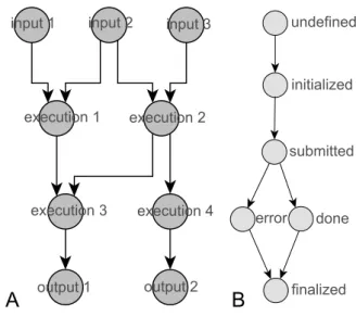
The execution model enables the parallelism extraction and a high level of task scheduling. The execution model is also a dataflow with input, execution, and output ac-tors (Figure 5-A), but each actor has 6 different states (un-defined, initialized, submitted, done, error, finalized) (Fig-ure 5-B). The states are defined to support asynchronous remote calls, a required pattern for long running job submis-sions. At the transition between states, a specific method is
launched. The transition between the state “submitted” and the state “done” corresponds to the UDF, here a bioinformat-ics tool. Each edge represents a data dependency. An edge links an output port of a source actor to an input port of a target actor and represents a channel of data tokens. Actors can have multiple input and output ports. Each workflow input is represented as a list of tokens. Conditional state-ments like “if else” structures can be represented using the propagation of a null token.
A dataflow model consumes and emits data tokens [14]. Two data token classes have been defined, a simple string for short values and a dataset Uniform Resource Identifier (URI). A dataset URI is an identifier that abstracts a file or a group of related files, like all files generated by an execution. This unified data container can seamlessly be used by the orchestration layer that manipulates abstract data tokens or by the services called internally by actors for data movement and the generation of data subsets.
An actor can emit one job output URI per invocation. In other words, each execution of an actor returns one URI for one command execution result set. At the scheduler level, this means that the number of tokens is predictable, allowing static scheduling and compliance with the Synchronous Data Flow model (SDF) [14].
input 1 input 2 input 3
execution 1 execution 2 execution 3 execution 4 output 1 output 2 undefined initialized submitted done error finalized
A
B
Figure 5: The execution model corresponds to a dataflow DAG (A) where execution actors wrap user-defined functions (UDF). Each actor has differ-ent states (B) to enable the control of asynchronous remote calls, directly during the orchestration.
4.1
Parallelism extraction
We focused on coarse grained parallelism. Defining im-plementation specific parallelism is out of the scope of this work but existing ones can be wrapped as UDF actors. For example, MPI or GPU implementation can be called using a particular job scheduler queue defined by an actor property. We now explains how the execution model specifically tar-gets different complementary levels of parallelism using:
(i) iterations (ii) data dependencies (iii) map-reduce
4.1.1
Iterations
All elements of a list of input tokens can be submitted in parallel. When an actor depends on multiple parameters (ports), each one linked to a list of input tokens, we can com-pute all parameter sets corresponding to all independent job submissions. As an example, it is similar to multiple parallel workflow instances execution with different parameter sets. The sequence of all parameter sets U of an actor is ob-tained by computing a cartesian product of all lists of input tokens connected to its input ports (Figure 6). In the case of an UDF actor F1 with two input ports, respectively pop-ulated with the lists of input tokens R and S , it corresponds to the generation of all possible pairs formed from the two lists, U = R× S. The resulting jobs are F1 (U ). Each el-ement of U is a set of parameters which can be applied to the function F1 in parallel.
u1←F1(r0,s1); u3←F1(r1,s1); u0←F1(r0,s0); u2←F1(r1,s0); R←{r0,r1} S←{s0,s1} T←{t0,t1} input R input S input T UDF F1(U) UDF F2(V) v1←F2(u1,t0) v3←F2(u3,t0) v0←F2(u0,t0) ; v2←F2(u2,t0) ; v5←F2(u1,t1) v7←F2(u3,t1) v4←F2(u0,t1) ; v6←F2(u2,t1);
Figure 6: Static computation of UDF actors job pa-rameter sets.
4.1.2
Data dependencies
Parallel executions among workflow actors is obtained by exploiting the graph topology. Following the dependency graph, any actor can be fired when all its predecessors have been fired. Each actor n associated with a set of param-eters represents a job submission s. The current states of all job submissions are stored in a synchronized data struc-ture. Reading the data structure holding the state of each defined job submission and the states of the related prede-cessors allows the scheduler to dynamically identify all job submissions that can be illegible for execution (algorithm 1). Then jobs can be submitted in parallel to a cluster job
sched-uler, following other implemented constraints, defined by the sheduling strategy.
Algorithm 1 parallelism extraction obtains from dynamic
scheduling using the data dependencies defined by the DAG topology.
D← setW orklowGraph()//workflow DAG
A← getAllJobSubmissions(D)//all job submissions for each n in D do
if (n is UDFActor ) then
P ← getP redecessors(n)//get all predecessors of n J← getJobSubmissions(n)//get reserved job // submission array
for each s in J do
if (s is not submitted ) then for each m in P do
t← getLinkedJobSubmission(m, s) //each submission of n is related to another //job submission of the predecessor actor m if (t is finished ) then
A(s)← T RUE //Job is defined as available // for future launch
for each s in A do if (A(s) is TRUE ) then
if (externalSchedulingCondition(s) is TRUE ) then p← new thread()
e← fire(p, s)//execute the job submission in a //new thread. Its results in multiple parallel //job executions on the target cluster
4.1.3
Map-Reduce patterns
In many application cases, a simple Map-Reduce pattern leads to the extraction of a massive coarse grain data paral-lelism from the workflow prototype. As previously defined, split and merge methods are Data Format Function (DFF). Within the execution model, DFF actors do not differ from UDF actors. It means that after model transformation, ac-cording to the user-defined annotations, a map reduce pat-tern is automatically inserted in the dataflow. For example, the actor node U DF (F 1) is replaced by a sub graph :
split→ UDF (F 1) → merge
A split method and a merge method can be applied on the same UDF actor on different UDF actors. In this last case, all data chucks are simply grouped using a shared dataset URI, and, thanks to this abstract data token, transparently routed in the dataflow graph.
5.
CONCLUSION
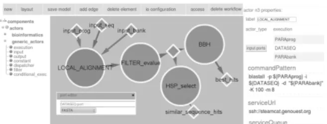
We have implemented a workflow engine based on our models. This engine can be integrated in a graphical WMS dedicated to intensive computation [1]. It generates an exe-cution model from the design model, previously created with a web workflow design GUI (Figure 7), and subsequently ex-ecutes the workflow [3].
Figure 7: Web workflow design GUI. The DAG corresponds to an intensive bioinformatics workflow captured using a graphical editor. For execution, the underlying workflow engine integrates a dedi-cated middleware, SLICEE (Service Layer for In-tensive Computation Execution Environment), em-bedded in actors
In this paper, we have proposed a modeling process of intensive bioinformatics workflows, closely related to the ac-tual observed development process. The transformation of an annotated design model to an execution model enables the extraction of different levels of coarse grain parallelism with minimum human intervention. By this way, the conver-sion of a low throughput prototype to a workflow adapted to intensive computation can be more easily achieved. It could also result in a larger dissemation of coarse grain parallelism usage in bioinformatics treatments, especially within popu-lar graphical WMS dedicated to non-technical users. In ad-dition, we have defined a minimal classification of the work-flow actors in two classes (UDF, DFF) that clearly highlights what can be automated or must stay user-defined.
However, the effectiveness of our approach depends on the structuration of a large corpus of utilitary methods related to bioinformatics types and formats. Major efforts still need to be made in those directions, especially, to study if the an-notation process of the design model, actually user-defined, could be automated. It would also be worth to investigate how model transformations could be used to seamlessly tar-get a larger scope of execution environments [10].
6.
REFERENCES
[1] Bioinformatics Intensive Workflow Portal.
http://workflow.genouest.org.
[2] Drmaa working group. http://www.drmaa.org/. [3] Slicee - Service Layer for Intensive Computation.
http://vapor.gforge.inria.fr/.
[4] P. Bui, L. Yu, and D. Thain. Weaver: integrating distributed computing abstractions into scientific workflows using python. In Proceedings of the 19th
ACM International Symposium on High Performance Distributed Computing, HPDC ’10, pages 636–643,
New York, NY, USA, 2010. ACM.
[5] A. Darling, L. Carey, and W.-c. Feng. The design, implementation, and evaluation of mpiBLAST. In
Proceedings of ClusterWorld Conference, pages 13–15,
San Jose, California, June 2003.
[6] J. Eder, W. Gruber, and H. Pichler. Transforming workflow graphs. In Proceedings of the first
international conference on interoperability of enterprise software and applications INTEROP-ESA 2005 ,Geneva, Switzerland, pages 203–215, 2005.
[7] Z. Farkas and P. Kacsuk. P-grade portal: A generic
workflow system to support user communities. Future
Generation Computer Systems, 27(5):454 – 465, 2011.
[8] J. Goecks, A. Nekrutenko, J. Taylor, and T. Team. Galaxy: a comprehensive approach for supporting accessible, reproducible, and transparent
computational research in the life sciences. Genome
Biol, 11(8):86, 2010.
[9] J. Ison, M. Kalas, I. Jonassen, D. Bolser, M. Uludag, H. McWilliam, J. Malone, R. Lopez, S. Pettifer, and P. Rice. EDAM: an ontology of bioinformatics operations, types of data and identifiers, topics and formats. Bioinformatics, 29(10):1325–32, May 2013. [10] L. Jourdren, M. Bernard, M.-A. Dillies, and S. Le
Crom. Eoulsan: a cloud computing-based framework facilitating high throughput sequencing analyses.
Bioinformatics, 28(11):1542–3, June 2012.
[11] S. Krishnan, B. Stearn, K. Bhatia, K. Baldridge, W. Li, and P. Arzberger. Opal: Simpleweb services wrappers for scientific applications. In Proceedings of
ICWS ’06. International Conference on Web Services, 2006., pages 823–832, 2006.
[12] O. Labbani, J. luc Dekeyser, P. Boulet, and E. Rutten. Introducing control in the gaspard2 data-parallel metamodel: Synchronous approach. In Proceedings of
the 1st International Workshop on Modeling and Analysis of Real-Time and Embedded Systems, 2005.
[13] A.-L. Lamprecht, S. Naujokat, B. Steffen, and T. Margaria. Constraint-guided workflow composition based on the edam ontology. In Proceedings of the
Workshop on Semantic Web Applications and Tools for Life Sciences, 2010.
[14] E. Lee and D. Messerschmitt. Static scheduling of synchronous data flow programs for digital signal processing. IEEE Transactions on Computers, 36(1), Jan. 1987.
[15] W. Li, S. Krishnan, K. Mueller, K. Ichikawa, S. Date, S. Dallakyan, M. Sanner, C. Misleh, Z. Ding, X. Wei, O. Tatebe, and P. Arzberger. Building
cyberinfrastructure for bioinformatics using service oriented architecture. In Proceedings of the sixth IEEE
International Symposium on Cluster Computing and the Grid, 2006. CCGRID 06., volume 2, pages 8
pp.–39, 2006.
[16] C. Lin, S. Lu, X. Fei, D. Pai, and J. Hua. A task abstraction and mapping approach to the shimming problem in scientific workflows. In Proceedings of SCC
’09. IEEE International Conference on Services Computing, 2009., pages 284–291, 2009.
[17] B. Lud¨ascher, I. Altintas, C. Berkley, D. Higgins, E. Jaeger, M. Jones, E. A. Lee, J. Tao, and Y. Zhao. Scientific workflow management and the kepler system. Concurrency and Computation: Practice and
Experience, 18(10):1039–1065, Aug. 2006.
[18] T. Oinn, M. Greenwood, M. Addis, M. N. Alpdemir, J. Ferris, K. Glover, C. Goble, A. Goderis, D. Hull, D. Marvin, P. Li, P. Lord, M. R. Pocock, M. Senger, R. Stevens, A. Wipat, and C. Wroe. Taverna: lessons in creating a workflow environment for the life sciences. Concurrency and Computation: Practice and