HAL Id: hal-01070549
https://hal.archives-ouvertes.fr/hal-01070549
Submitted on 7 Oct 2014
HAL is a multi-disciplinary open access
archive for the deposit and dissemination of
sci-entific research documents, whether they are
pub-lished or not. The documents may come from
teaching and research institutions in France or
abroad, or from public or private research centers.
L’archive ouverte pluridisciplinaire HAL, est
destinée au dépôt et à la diffusion de documents
scientifiques de niveau recherche, publiés ou non,
émanant des établissements d’enseignement et de
recherche français ou étrangers, des laboratoires
publics ou privés.
Frame-based Modeling for Automatic Synthesis of
FPGA-Software Defined Radio
Ganda Stephane Ouedraogo, Matthieu Gautier, Olivier Sentieys
To cite this version:
Ganda Stephane Ouedraogo, Matthieu Gautier, Olivier Sentieys. Frame-based Modeling for
Auto-matic Synthesis of FPGA-Software Defined Radio. 9th International Conference on Cognitive Radio
Oriented Wireless Networks, Jun 2014, Oulu, Finland. pp.203-208. �hal-01070549�
Frame-based Modeling for Automatic Synthesis of
FPGA-Software Defined Radio
Ganda Stephane Ouedraogo, Matthieu Gautier and Olivier Sentieys
IRISA, INRIA, University of Rennes 1, France[email protected]; [email protected]; [email protected]
Abstract—Software Defined Radio (SDR) is now becoming a ubiquitous concept to describe and implement Physical Layers (PHYs) of wireless systems. Moreover, even though the FPGA is expected to play a key role in SDR, describing a PHY at the Register-Transfer-Level (RTL) requires tremendous efforts. This paper introduces a novel methodology to rapidly implement PHYs for SDR. The work relies upon High-Level Synthesis tools and dataflow modeling in order to infer an efficient RTL control unit for the application. The proposed software-based over-layer partly handles the complexity of programming an FPGA and integrates reconfigurable features. It consists essentially of a Domain-Specific Language (DSL) combined to a DSL-Compiler. An IEEE 802.11a transceiver has been explored via this approach in order to show the flexibility features.
I. INTRODUCTION
Software Defined Radio (SDR) is a concept that has come to maturity [1]. According to the wireless innovation forum [2], an SDR is a radio in which some of the physical layer (PHY) functions are software defined. Indeed, these radios are mainly characterized by their ability to support different waveforms. Different attempts to standardized SDR have led to two major works, namely the Software Communication Architecture (SCA) [3] and the Space Telecommunication Radio System (STRS) [4]. These two frameworks provide the building environment for SDR, however a need for tools to design the PHY is still pointed out. The GNURADIO [5] and the SDRPHY [6] projects are examples of software frameworks. They both use a block-based model of the PHY applications, namely a dataflow program, to implement such PHYs.
The dataflow Model of Computation (MoC) [7] has en-countered a lot of success in the real-time signal processing domain. It describes an application as a set of functional blocks that run concurrently and communicate through FIFO channels. This view of the MoC represents the processing unit of the application, which is usually associated to a control unit. This associated control unit can be modeled as a Finite State Machine (FSM), which provides a behavioral description of the application. In most of the SDR frameworks, the functional description of the blocks are written using high-level languages such as C/C++ and the application runs over Digital Signal Processors (DSP) based platforms. Blocks can be also written at the register level (RTL) level by using a Hardware Description Language (HDL) and run over Field Programmable Gate Array (FPGA), however this description differs from the initial idea of SDR where the blocks are
software defined.
In this paper, a novel software over-layer to specify a PHY and implement it over FPGA platforms is proposed. Indeed, the nascent radio protocols are expected to meet a certain data throughput and the FPGAs include specialized resources such as DSP slices, Block-RAM (BRAM) and clocking resources, which enable achieving such data throughput requirements. The proposed design flow relies upon High Level Synthesis (HLS) tools [8] that provide a mean to compile an abstracted description (C/C++) of an application down to its RTL de-scription. To enable the specification of a multi-rate dataflow application running on FPGA, the main contributions describes in the paper are:
• a Domain Specific Language (DSL) [9] which provides
the primitives to rapidly prototype the dataflow applica-tions meant for SDR. The DSL is combined to HLS tools to take advantage of their features.
• a data frame-based algorithm to automatically generate
an appropriate control unit capable of handling the re-configuration issues of a multi-rate complex dataflow specification.
The paper is structured as follows. In Section II a discussion over the chosen dataflow model of computation is held, together with its requirements in terms of control. Section III details the frame-based algorithm to generate the control struc-ture given a high level specification of a dataflow application. Section IV discusses an example through the specification of the IEEE 802.11a standard with the proposed framework. Finally a conclusion is drawn while future work is discussed.
II. IMPLEMENTINGDATAFLOWMODELS FOR SDR
A. The Dataflow MoC and Control Modeling for SDR
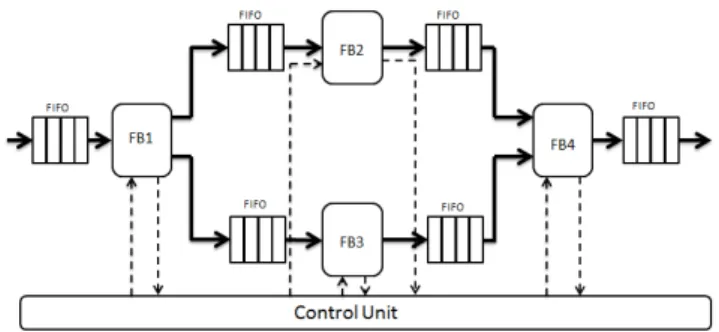
A MoC is an abstract specification of how the computation is managed. Radio link applications can be modeled using the Synchronous Data Flow (SDF) MoC [10]. This MoC represents a program as a directed graph in which each node, communicating via channels, consumes or produces a prede-termined and fixed number of data (tokens) per invocation. An example of SDF signal flow graph is given in Fig. 1, where FB1, FB2, FB3 and FB4 denote functional blocks (FBs) communicating through channels. An SDF implementation requires a static scheduling and SDF was employed in various embedded systems design tools such as the development environments derived from the Ptolemy project [11].
Fig. 1. SDF signal flow graph example.
A typical SDF-based dataflow architecture is given in Fig. 2 where the FBs depict the computing cores. Fig. 2 can be interpreted as an implementation of the graph in Fig. 1. At the inputs and outputs of the FBs, FIFOs are interfaced to control the streaming flow. An important element that is making the waveform structure consistent is the control logic, which purpose is to orchestrate the data routing and computing in graph. Indeed, it provides the system with specific signals that are used to change the state of the system. This generic overview of the dataflow architecture clearly shows that, for efficiency purposes, enhancements can be performed at three distinct levels, namely the FBs, the communication infrastruc-ture and finally the control unit. In this work, the FBs and the communication infrastructure are synthesized using HLS tools/languages as it will later be explained. An emphasis is given on the controller required to schedule the resulting waveform running on an FPGA device in context of multi-rate SDR.
On a running platform such as FPGA on which each function is mapped to dedicated resources, an FSM is a good candidate to implement a control unit. Its main task is to handle consistently the traversal of data through the graph. Thus, depending on the current state and the conditions on the inputs and outputs channels, the controller activates or deactivates a set of FBs. This approach is only valid when the properties of the graph remain unchanged. The FSM in this case appears to be relatively simple to implement. In the context of SDR, some part of the graph could be reconfigured at run-time. For instance, most of modern standards [12] [13] implement Adaptive Coding and Modulation (ACM) technique in order to enhance the bandwidth efficiency. ACM consists in adapting the modulation and coding schemes according to the environment. Thus, each part of the data frame may be modu-lated or coded differently. On the receiver side, data should be
Fig. 2. Typical SDF dataflow RTL architecture.
decoded with the appropriate demodulation algorithm so that the decoding remains consistent. Modern waveforms require a controller that can switch between configurations at run-time. This example further illustrates the fact that the control re-quirements are more complex in the context of SDR. Changing some parts of the waveform (i.e. the dataflow) at run-time is quite complex. This complexity in terms of processing and control in modern PHYs led the designers to re-think the overall designing process. The HLS partly addressed these issues by enabling to go straight from specifications to the implementation. Nonetheless, issues relative to control remain while considering HLS.
B. HLS for Rapid Prototyping
A typical FPGA-based development process of a dataflow application is twofold. The first part consists in specifying the system in an abstracted way using High-Level Languages (HLL) such as C/C++ or Matlab. This representation highlights the sub-elements of the system and their interactions. It often considers streaming data as floating-point data types that are refined to fixed points when it comes to implementation. The second part consists in a hardware description of the system. Hardware Description Languages (HDL) such as Verilog or VHDL are used to implement the specification previously written in HLL. The implementation gives a functional de-scription of the system and takes account of the computing and communication resources available. A mainstream trend is to merge these two designing steps into a single one. The HLS bridges the gap between the specification and the implementation. It takes as an input a function specification written in a HLL and generates its RTL description for a specific target platform (e.g. FPGA). The existing HLS tools emphasize on the functional aspects of the application and they propose several design optimization techniques to fulfill the performance requirements without shortcomings.
In the context of FPGA-based SDR, HLS significantly helps with rapid prototyping. As aforementioned, it shortens the design time and improves the overall productivity. Thus, given the requirements in terms of flexibility of SDR and the capabilities of HLS, integrating HLS within an SDR-PHY design flow can yield the development process. A preceding study [15] consisted in showing the gain for an HLS-based de-sign flow. To this end, a software-based over-layer is proposed to abstract the SDR-PHY designing process and anticipate on SDR requirements. In our design flow, we will consider FBs being specified in HLL and synthesized by HLS tools.
III. A FRAME-BASEDDATAFLOWMODELING
Data framing is imposed by most of the modern radio protocols and often specified accurately by the wireless stan-dards [12] [13]. A frame is composed of fields, conveying various type of information. This structure enables a consistent data coding and decoding while ensuring the inter-operability of software and hardware solutions released in the market. By considering a unique data frame structure, the designers are given the freedom to implement the solutions to process the
frame. The resulting datapath and control are deeply associated to structure of the data frame.
A. High Level Modeling of FPGA-SDR Waveform
The growth of the platforms complexity exhibits the limi-tations of the current programming languages. Furthermore, these platforms evolve rapidly while the application codes are still written and maintained manually. A mainstream approach to handle such platform evolution is the Model-Driven Engineering (MDE) [14]. It comprises both Domain-Specific Languages (DSL), which formalize the application structure behavior and requirements in a declarative way, and transformation engines and generators to generate multiple artifacts such as source code. The MDE approach ensures a ”correct-by-construction” development of the final product.
One of the interests of working with models is the pos-sibility to automate different steps throughout the develop-ment process. The principal advantage is the automatic code generation achieved from these models. In addition, they can gradually evolve to cover a larger spectrum of capabilities. The models also give a mean to infer diverse information, such as the control, and shorten considerably the system development time. We have defined a DSL which provides the primitives to model a dataflow waveform. This language is featured with the HLS tools and is detailed later in this paper. It combines both a data-path and data-frame specification to build the processing and the control units for an SDR waveform. Methodologies for automatic hardware synthesis from data frame specifications are not often discussed in the literature. An example is given in [6], where an XML-based SDR waveform specification flow including frame definition is discussed. It is called SDRPHY and is a proposal for SDR physical layers specification using XML as an entry point by contrast to our approach based on a brand new DSL. XML hardware-specific interpreters are used to convert the XML physical layer description for a specific running platform. Thus, this approach focuses more on the portability of the SDR waveform over various running platforms and the HLS features are not included.
Our solution is quite similar while relying on a DSL. It is also specific to FPGA-based SDR. An algorithm is proposed to infer a control unit from a DSL specification as discussed in the next section.
B. Frame-based SDR Waveform Control Description
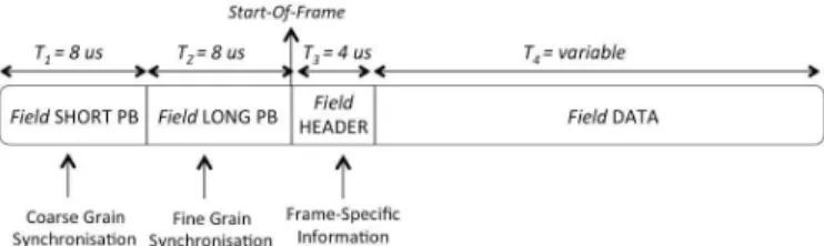
A frame is generally considered at distinct levels, namely the bit level, the symbol level, and optionally the sample level. It is mainly characterized by its duration, its source (e.g. an FB) and is composed out of fields. The nature of the data conveyed by each field can be either specific information (e.g. modulation schemes or coding rate), synchronization information (e.g. preamble) or useful data (e.g. data payload). An OFDM frame is given as an example in Fig. 3 where each field is characterized by its duration and the type of transported data.
One can notice that the structure of a frame gathers ex-ploitable information (duration, source, data properties) that
Fig. 3. IEEE 802.11a data frame.
can be leveraged to achieve better control performance. The duration of each field helps generating the read and write clock signals during the appropriate slot of time. The oversampling or down sampling mechanisms imply some rate changes that are tracked across the graph. To manage the block-level communication, FIFOs are interfaced between two consecutive blocks. In our approach, these FIFOs are inferred from the specifications. They are implemented by HLS tools by using the FPGA memory resources. In addition, each block within the graph is meant to perform a given action on a specific set of data. Once this action terminates, the blocks may no longer be required then disabled. For instance, some functional blocks may address only synchronization and some others address only data decoding. It is then convenient to control the activation and deactivation of each FB.
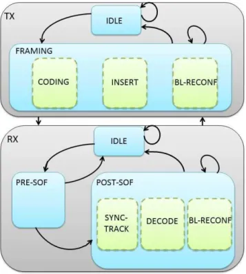
The inferred control unit is an FSM working in both transmitter (TX) and receiver (RX) modes. Its overall structure is given in Fig. 4, where dash lines denote parallel states. In TX mode, the controller first waits for a start signal from the upper layers indicating that a data frame is available. In this mode, the controller consists of two major states called
super-states. First is the IDLE super-state corresponding to the inactive state of the transmitter. After detecting a start from the MAC layer for example, it transitions from the IDLE to the FRAMING super-state where data coding is sketched. Generally speaking, dataflow transmitters are feed-forward architectures hence less complex to implement as compared to their associated receiver. The FRAMING super-state is de-clined into three parallel sub-states namely, the CODING state, the INSERT state and finally the BL-RECONF state. In the
CODING, typical mapping operations together with filtering operations are performed. The output samples are fed to the DACs (Digital to Analog Converter) prior to carrier frequency modulation. In parallel to the CODING state, an INSERT state is active. This state manages the insertion of specific data in the frame, both at the time and spectral levels. Considering the standards using an OFDM modulation, they require to inject pilot symbols from time to time within the spectrum for coherent detection. Moreover, a data frame often includes constant fields (e.g. preamble) that remain the same in all the transmitted frames. For the purpose of reducing the overall computation, such fields are one-time computed and inserted (at run-time) at the sample level in the frame before DACs. The BL-RECONF state handles the block-level (fine-grained) reconfiguration of the transmitter. As aforementioned, modern standards require certain blocks to be adaptive (ACM) i.e.
Fig. 4. Transceiver FSM.
changing their properties on-the-fly. One approach consists in hard-coding all the configuration of the block once, then using software controlled switch to select the desired configuration at run-time. A second approach is to reconfigure the block when a given configuration is desired. It is a suitable approach which fits the best to the paradigm of SDR and requires indeed partial reconfiguration capabilities.
In RX mode, the FSM is composed of three super-states. An
IDLE state, as in TX mode, denotes the inactive state of the
receiver. In this state, the receiver monitors the environment seeking for an incoming signal. Once a signal is detected through an RSSI (Received Signal Strength Indicator) for instance, the receiver transitions from the IDLE state to the
PRE-SOF state. The PRE-SOF state consists essentially of synchronization tasks as imposed by most of the standards. Once the system enters the PRE-SOF state, a set of synchro-nization elements has to be detected and computed within a certain delay. If not, the system returns in the IDLE state. These synchronization elements detection and computation are associated to an event that is called Start-Of-Frame (SOF). An SOF detection makes the system transition from PRE-SOF to POST-SOF where a coherent data decoding is sketched. The POST-SOF state is declined into three parallel sub-states namely, the DECODING state where most of the signal processing is required, the SYNC-TRACK state in which the system keep on tracking synchronization elements and finally the BL-RECONF state to handle the run-time block-level reconfiguration as in TX mode.
In each of the states, a set of dataflow computation is intended. In the context of FPGA, the data-path is once
mapped to dedicated resources and ready to operate as soon as the FPGA is powered on. One of the roles of the controller is to distribute the clock signal to activate or deactivate the FBs when required. We leverage the properties of the data frame together with the intrinsic structure of the data-path (dataflow) to build the control unit. First, a data frame F is as a collection of fields i.e.:
F = ∪Ni=1Fi, (1)
where Fi denotes the i-th field. Each field Fi is characterized
by its duration Ti its constant or variable nature State of its
transported data P ayload:
Fi= {Ti, State, P ayload}. (2)
The duration TF of the overall frame F is computed as:
TF =
N
X
i=1
Ti. (3)
The datapath, on both the transmitter and receiver side, is a set of interconnected FBs as illustrated in Figure 2. They are characterized by their latency (L), throughput (T P ), input and
output data rates (finand fout). For each block, the inputs and
outputs rate are known and they can be managed using enable signals. Moreover, each block is activated or deactivated on a per-field basis since computation happens to be specific to a
given field. Thus, let F Bj be the j-th FB within the dataflow
graph:
F Bj = {finj, foutj, Lj, T Pj}. (4)
Assuming that F Bj processes the field Fi of duration Ti at
an input rate of finand output rate of fout, the block requires
being enable a number to time equals to:
ki,j = Tifin. (5)
Thus, each block is affected a time slot to process a field when this field is traversing the graph. They are then activated depending on the ongoing field. To achieve this, the controller decides a starting moment for each block in the graph. This starting time is computed by considering both the graph struc-ture and the properties (latency and throughput) of each block composing it. Indeed, each state is associated to a distinct data-path and once the system enters a state, the processing starts with a specific block that is tagged as a reference block. The activation moment of the remaining blocks in the graph is then estimated based on the latency and the throughput of the blocks preceding them. Blocking reads and blocking writes are also implemented since the blocks are interfaced with FIFOs. This algorithm has been integrated into an SDR PHYs de-sign flow. The flow is implemented as a DSL which addresses rapid prototyping of the PHY. It relies on the principle of the MDE and its details are discussed in the next section.
IV. IMPLEMENTATION OF THE CONCEPT FOR AN SDR DESIGN FLOW
In this section, a design flow that was defined to enable rapid prototyping of FPGA-based SDR physical layers is presented. In addition, a practical example of a radio protocol specification is depicted as proof of concept. This flow relies on a DSL which enables to specify a data frame, its attributes and a data-path. A DSL-Compiler is provided to both infer the control unit of the physical layer and operate the connection between the instantiated blocks. The instantiated FBs are compiled down to RTL with HLS tools that are integrated to the flow.
A. A Dedicated DSL to Model SDR-PHY
The idea to define a new language instead of using an existing language aims first at making the most of the expres-siveness given by a specialized language. A DSL can be either internal or external [9]. An internal DSL is a language that is nested within a host language. The host language is generally a well-known General Purpose Language (GPP) such as C++ or Java. External DSLs in opposition enable to explicit any domain by defining a new syntax and an appropriate grammar. They require a lot more efforts to be implemented but they remain much less constrained in comparison to internal DSLs. An external DSL has been defined to model the PHYs meant for SDR applications running on FPGA devices. The DSL provides the primitives to describe on one side the data frame and on the other side the data-path by considering the data frame attributes. A frame is considered as a collection of fields that are destined to be processed independently by the FBs of the processing unit. A typical specification with the DSL starts by including FBs HLS-based libraries. After that, a set of data rates are defined in order to model the multi-rate constraints within the graph. These definitions are used to impose reading and writing rates to the different blocks. Then, each field of the data frame is described independently by highlighting some of their features like duration or eventually data redundancies for optimization purposes. Constant fields are stamped with the key word #fieldC. They are once computed, in contrast to variable fields that are specified with the key word #fieldV and modulated through the data-path. In RX mode, since the system requires a detection of an SOF to switch from the
PRE-SOF to the POST-SOF state in order to further process the data, one of the fields is designated as an SOF. This field is typically a preamble that is appended for synchronization purposes.
The data-path is described by using a set of heterogeneous FBs that are sourced from HLS-based libraries. The instantia-tion of each block requires specifying both the inputs and the outputs data rates using the rates defined at the beginning of the specification. The idea is to provide a rich description for each block in order to optimally synthesize the corresponding RTL. The HLS tool intended for each block is specified at that time by using the annotations #catapultc or #vivadohls. Indeed, an important development work has been carried out to implement multiple FBs that are gathered in libraries. So
far, those blocks are synthesizable either by CatapultC from Calypto or by Vivado-HLS from Xilinx. An ongoing work aims at including native RTL FBs, by using the annotation #rtl. Furthermore, real-time constraints for each block are taken into account. These constraints are the latency, the throughput or the clocking requirements of the block that are further used to implement the control unit of the waveform. The provided DSL-Compiler generates, for each FB, a .tcl script which is used as an interface with the intended HLS tools to synthesize the RTL solution. The compiler is also charged of the consistent gluing of the generated RTL solutions by using RTL wrappers. It also performs some type checking and many other verification in order to ensure consistency in the final waveform.
As discussed in Section III-B both the frame and the data-path are used to infer the control unit and the DSL provides an environment to describe a rich specification of these two aspects of a waveform. An important feature that was added in the DSL is to clearly mention, for each FB, a list of the fields that it is intended to process and their respective source (i.e. another FB) by using the key words processing and from respectively. These information make it possible to track each field within the graph hence activating the FB when required. The DSL-Compiler parses these information and generates the controller.
Another feature that is making this flow specific to SDR is the fact enabling the reconfiguration of FB at run-time. Indeed, all the FBs that are subject to run-time reconfiguration are annotated with the key word adaptive. In practice, they are defined into Partial Reconfiguration Region on the FPGA and interfaced with larger memory resources in order to store the incoming data stream while operating the reconfiguration. Once the system enters the BL-RECONF state, all the blocks that are not impacted by the reconfiguration are held active by the controller while the rest of the graph is being stalled. As soon as the reconfiguration terminates the data coding or decoding is performed normally.
B. A Case Study through the IEEE 802.11a PHY
Remembering the structure of the frame illustrated in Fig. 3, a piece of prototype of an IEEE 802.11a PHY is presented. In Fig. 5, a piece of DSL-based description of an IEEE 802.11a [13] source code is provided. Constant fields are sourced from local files and mapped to memories. They are multiplexed to the rest of the frame at run-time when required. Variable fields are sourced from upper layers or different FBs. The details of the DSL-Compiler are not in the scope of this paper. Its main task is to parse the DSL and then to infer the desired control unit. The SHORTPB for instance is appended for synchronization purpose. It is a constant field that remains the same for any data frame. Moreover, this field is computed only by the synchronization FBs. It has an overall duration of 8 microseconds that sets a deadline for the FBs intended to process this field. The DATA field conveys the data payload from the upper layer. Both its content and its size vary on a per-frame basis. The exact size of the field is embedded in the
/ / S h o r t t r a i n i n g f i e l d s p e c i f i c a t i o n # f i e l d C SHORTPB{ c o n s t a n t S h T r a i n i n g S b : . / s h p b . d a t ; redundancy 1 0 ; d u r a t i o n 8 us ; } / / Long t r a i n i n g f i e l d s p e c i f i c a t i o n # f i e l d C LONGPB{ c o n s t a n t L g T r a i n i n g S b : . / l g p b . d a t ; redundancy 2 ; d u r a t i o n 8 us ; } / / He ade r ( SIGNAL ) f i e l d d e f i n i t i o n # f i e l d V HEADER{ d a t a h d p a y l o a l ; s i z e 3 b y t e s ; d u r a t i o n 4 us ; } / / DATA f i e l d s p e c i f i c a t i o n # f i e l d V DATA{ d a t a d t p a y l o a d ; m a x s i z e 2312 b y t e s ; m i n s i z e 0 b y t e s ; } / / OFDM PPDU s p e c i f i c a t i o n
complex frame PPDU{
SHORTPB , LONGPRB, HEADER, DATA } s o f a f t e r SHORTPB / / FFT i n s t a n t i a t i o n f f t i : a d a p t i v e i p FFT p r o c e s s i n g LONGPB HEADER DATA from c p r e m o v a l i{ read cpRemov on p o r t f f t i n a t f e ; w r i t e c p l x s y m b o l on p o r t f f t o u t a t f s ; c o n s t r a i n t l a t e n c y N ; }
Fig. 5. DSL-based IEEE 802.11a PHY.
frame within its HEADER field. Only a range is provided by the standard and most of the solutions usually consider a fixed size not to bother with the control requirements. The inferred control unit handles this issue by generating a stop signal after the exact DATA field time has elapsed. A complex (consisting of in phase and quarter-phase channel) is built out of the fields and the SHORTPB is designated as Start-Of-Frame.
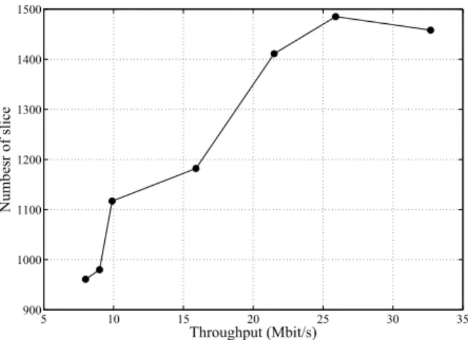
An adaptive Fast Fourier Transform (FFT) block, as the main block of the IEEE 802.11a PHY, specification is also given in Fig. 5. It corresponds to a set of FFT blocks varying by the size of the FFT. Partial reconfiguration technique is used to configure the desired FFT at run-time. In order to comply with the requirements of partial reconfiguration, i.e. non varying I/O set between two configurations, we have made the FFT input and output non vector type. The samples are then reordered inside the FFT for a given FFT size. Fig. 6 shows a design space exploration for a 256-point FFT, performed with CatapultC in order to obtain different solutions of the same design. The solutions were synthesized for a Virtex 6 FPGA platform by using the Xilinx ISE tool suit and the results are collected after place and route. It is important to mention that as the FPGAs are getting larger,
i.e. including more resources; it is now possible to program
complex waveforms into a single one. This exploration shows indeed an increasing number of slices depending on the data rate. Hence suitable solution can be chosen for the final design.
V. CONCLUSION
SDR is an outstanding concept that requires to be further developed. As the FPGA technology evolves, it turns out
5 10 15 20 25 30 35 900 1000 1100 1200 1300 1400 1500 Throughput (Mbit/s) Numbesr of slice
Fig. 6. Resource estimation versus Datarate of the IEEE 802.11 receiver.
to be a good candidate for SDR solutions. The MDE ap-proach is a promising alternative toward the optimization of the development process of an embedded system in general. Our contribution is essentially to bring together both SDR and MDE concepts into an SDR-PHY design flow, with an emphasis on control aspects. The flow is featured with the nascent HLS tools and implements several PHY artifacts from the specifications. This combination enables to achieve good design performance, thanks to HLS tools, and to significantly shorten the required development time.
REFERENCES
[1] Dr. Joseph Mitola III, Software radios: Survey, Critical Evaluation and
Future Directions. IEEE Aerospace and Electronic Systems Magazine, 8(4):25-36, April 1993.
[2] Wireless Innovation Forum, Driving the future of radio communications and systems worldwide http://www.wirelessinnovation.org
[3] J. Bard, Software defined radio: the software communication architecture. Wiley, New York, 2007.
[4] Reinhart RC et al (2010), Space Telecommunications Radio System
(STRS) architecture standard. NASA glenn research center, Cleveland, TM 2010-216809
[5] GNU Radio, The free and open software radio ecosystem http://www.gnuradio.org
[6] E. Grayver, H.S. Gree, J.L. Roberson, SDRPHY - XML Description for
SDR Physiczl Layer. The 2010 Military Communications Conference -Unclassified Program - Systems Perspectives Track, 2010.
[7] Stephen A. Edwards, Language for digital embedded systems. Kluwer Academic Publication, 2000.
[8] Stephen A. Edwards, The Challenges of Synthesizing Hardware from
C-Like Languages.
[9] M. Fowler and R. Parsons, Domain-Specific Languages. The Addison-Wisley Signature Series, 2011.
[10] E.A. Lee and D.G. Messerschmitt, Synchronous data flow. Proceedings of the IEEE, 36(1) : 24-35, 1987.
[11] Johan Eker, Jorn Janneck, Edward A. Lee, Jie Liu, Xiaojun Liu, Jozsef Ludvig, Sonia Sachs, Yuhong Xiong, Taming heterogeneity - the Ptolemy
approach. Proceedings of the IEEE, 91(1):127-144, January 2003. [12] IEEE Standard for Information Technology, Wireless Medium Acess
Control (MAC) and Physical Layer (PHY) Specifications for Low-Rate Wireless Personal Area Networks (WPANs). IEEE Std 802.15.4-2006. [13] Supplement to IEEE Standard for Information Technology, Wireless
LAN Medium Access Control (MAC) and Physical Layer (PHY) Specifi-cations. IEEE Computer Society-1999.
[14] Douglas C. Schmidt, Model-Driven Engineering. IEEE Computer (Vol. 39, No. 2) pp. 25-31, 2006.
[15] V. Bahtnagar, G. S. Ouedraogo, M. Gautier, A. Carer and O. Sentieys
An FPGA Software Defined Radio with a High-Level Synthesis Flow. IEEE Vehicular Technology Conference (VTC-Spring13), June 2013.