HAL Id: tel-02095994
https://tel.archives-ouvertes.fr/tel-02095994
Submitted on 11 Apr 2019HAL is a multi-disciplinary open access archive for the deposit and dissemination of sci-entific research documents, whether they are pub-lished or not. The documents may come from teaching and research institutions in France or abroad, or from public or private research centers.
L’archive ouverte pluridisciplinaire HAL, est destinée au dépôt et à la diffusion de documents scientifiques de niveau recherche, publiés ou non, émanant des établissements d’enseignement et de recherche français ou étrangers, des laboratoires publics ou privés.
François Lemercier
To cite this version:
François Lemercier. Multiple interface management in smart grid networks. Networking and Internet Architecture [cs.NI]. Ecole nationale supérieure Mines-Télécom Atlantique, 2018. English. �NNT : 2018IMTA0100�. �tel-02095994�
IMT Atlantique
Bretagne-Pays de la Loire ´
Ecole Mines-T ´el ´ecom
T
H `
ESE DE DOCTORAT DE
L’
E
´
COLEN
ATIONALES
UPERIEUREM
INES-T
ELECOMA
TLANTIQUEB
RETAGNEP
AYS DE LAL
OIRE -IMT A
TLANTIQUEC
OMUEU
NIVERSITEB
RETAGNEL
OIREEcole Doctorale N°601
Math `ematique et Sciences et Technologies
de l’Information et de la Communication (MathSTIC) Sp ´ecialit ´e : Informatique
Par
Franc¸ois LEMERCIER
Multiple Interface Management in Smart Grid Networks
Gestion d’interface multiple dans les r ´eseaux smart grids.Th `ese pr ´esent ´ee et soutenue `a RENNES, le 20/11/2018
Unit ´e de recherche : Institut de recherche en informatique et syst `emes al ´eatoires (IRISA) Th `ese N°: 2018IMTA0100
Rapporteurs avant soutenance :
Andr ´e-Luc BEYLOT – Professeur, ENSEEIHT Engineering School, Universit ´e de Toulouse, France Antoine GALLAIS – Maˆıtre de conf ´erences, INRIA, Universit ´e de Strasbourg, France
Composition du jury :
Pr ´esidente : Mireille BATTON-HUBERT – Professeure, Ecole des Mines de Saint Etienne, France
Examinateurs : Andr ´e-Luc BEYLOT – Professeur, ENSEEIHT Engineering School, Universit ´e de Toulouse, France
Antoine GALLAIS – Maˆıtre de conf ´erences, INRIA, Universit ´e de Strasbourg, France Nicolas MONTAVONT – Professeur, IMT Atlantique, IRISA, France – Encadrant de th `ese Philippe CHIUMMIENTO – R&D Manager, Itron, France
Dir. de th `ese : Laurent TOUTAIN – HDR, IMT Atlantique, IRISA, France – Directeur de th `ese
D E C L A R AT I O N
I hereby declare that except where specific reference is made to the work of others, the contents of this dissertation are original and have not been submitted in whole or in part for consideration for any other degree or qualification in this, or any other university. This dissertation is my own work and contains nothing which is the outcome of work done in collaboration with others, except as specified in the text and Acknowledgments.
Rennes, September 20, 2018
6lowpan IPv6 over Low power Wireless Personal Area Networks ami Advanced Metering Infrastructure
amr Automated Meter Reading
aodv Ad Hoc On-Demande Distance Vector Protocol bb Broadband
ble Bluetooth Low Energy
csma/ca Carrier Sense Multiple Access with Collision Avoidance d8psk Differential Eight Phase Shift Keying
dadr Distributed Autonomous Depth-First Routing dag Directed Acyclic Graphs
dao Destination Advertisement Object dbpsk Differential Binary Phase Shift Keying dc Data Concentrator
ddr Data Delivery Ratio dio DAG Information Object dis DAG Information Solicitation dodag Destination Oriented DAG
dqpsk Differential Quaternary Phase Shift Keying dsp Digital Signal Processor
ett Expected Transmission Time etx Expected Transmission Count ev Electric Vehicle
g2v Grid to Vehicle han Home Area Network
hsdpa High Speed Downlink Packet Access hv High Voltage
ietf Internet Engineering Task Force iot Internet of Things
ip Internet Protocol
load 6LoWPAN Ad Hoc On-Demand Distance Vector Routing
loadng Lightweight Ad hoc On-demand Distance-vector Routing Protocol Next Generation
lql Link Quality Level lv Low Voltage
mdms Meter Data Management Systems mp2p Multipoint-to-Point
mptcp Multipath TCP
mrhof Minimum Rank with Hysteresis Objective Function mv Medium Voltage
nan Neighborhood Area Network nb Narrow Band
nbi Narrow-band Interference nsa Node State and Attribute nt Neighbor Table
of Objective Function of0 Objective Function Zero
ofdm Orthogonal frequency-division multiplexing olsr Optimized Link State Routing Protocol os Operating System
p2p Point-to-Point
p2mp Point-to-Multipoint pan Premise Area Network pc Personal Computer pdr Packet Delivery Ratio plc Power Line Communication pmu Phasor measurement unit qos Quality of Service
rrep Route Reply rreq Route Request
robo Robust Orthogonal Frequency Division Multiplexing rpl IPv6 Routing Protocol for Low-Power and Lossy Networks rtu Remote Terminal Units
scada Supervisory Control and Data Acquisition sm Smart Meter
snr Signal Noise Ratio unb Ultra Narrow Band v2g Vehicle to grid wan Wide Area Network wmn Wireless Mesh Network wsn Wireless Sensor Network
Dedicated to my wonderful wife Gwenaëlle and our fantastic daughter Zoé, you bring so much love into my life!
A B S T R A C T
The power grid is undergoing a tremendous evolution, toward what is called the Smart Grid. The necessity of incorporate renewable energy sources in the grid, the decentralized productions, the increasing of consumption, etc. are some of the challenges in an energy network where sustainability, security and affordability are required. The grid is actually evolving from a centralized architecture to a decen-tralized one, taking into account all the unpredictable sources and consumption an energy network should handle in the future.
The Advanced Metering Infrastructure is the network dedicated to the Smart Grid that allows two-ways communications between the consumers and the energy providers. Consumers are linked to the AMI with meters having advanced com-munication and computing technologies: the Smart Meter. Today Smart Meters are often equipped with multiple communication interfaces but only one is used for principal Smart Grid communication, the other one having a dedicated function (such as firmware update, etc.).
The Smart Meters network is commonly based on Power Line Communications, a technology that is subject to high sensitivity to interference. Despite a dedicated MAC protocol, such as P1901.2, that could face the high variation of the available bandwidth, this technology does not allow to fulfill the requirements of all smart grid applications (i.e. the 99.99% reading rate). Alternative communications tech-nologies exist to tackle the issues of PLC, such as wireless or fiber optic, but using one of those technologies does not appears to be a long term solution. Consequently, mixing multiple heterogeneous technologies allow to cope with all scenarios and interference levels.
Most of the technologies considered for smart meters network are short range, nodes cannot reach the concentrator directly. Consequently, nodes must collaborate using a dedicated routing protocol, to reach a destination that is multiple hops away. RPL is the most popular routing protocol in the IoT community, and specifically designed to operate on Low Power and Lossy networks. But it is mostly used in homogeneous networks with single communication devices.
The goal of this thesis is to adapt RPL as it could work with multiple interfaces, and study how the heterogeneity of the interfaces could increase the reliability and the performance of smart meter networks.
To this end, we propose a new framework to extend RPL by managing multiple heterogeneous interfaces and we introduce three original solutions which are the Parent Oriented, the Interface Oriented and the Multiple Instances. We propose a
Finally, we implemented our solutions in both simulation and hardware environ-ment to validate and compare each one with realistic conditions.
R É S U M É
Le réseau électrique a subi d’importantes évolutions ces dernières décennies, pour devenir ce qu’on appelle le Smart Grid. La nécessité d’intégrer des sources d’énergie renouvelable est un défi dans un réseau d’énergies où l’accessibilité, la maintenabilité et la sécurité sont requis. Le réseau électrique évolue actuellement d’une architecture centralisée vers une architecture décentralisée, tenant compte des consommations et sources d’énergies à caractère imprédictible et irrégulier.
L’Advanced Metering Infrastructure est une architecture clé du Smart Grid qui permet des communications bidirectionnelles entre le consommateur et le four-nisseur d’énergie. Cette infrastructure repose sur des compteurs dotés de capacités de communication et de calculs avancés, que nous appelons "compteur intelligent". Les compteurs intelligents d’aujourd’hui sont souvent capables de communiquer avec plusieurs interfaces de communication mais seulement une seule est dédiée aux applications Smart Grid, les autres interfaces étant dédiées à des fonctions spécifiques (comme la mise à jour du firmware, etc.).
Les réseaux de compteurs intelligents reposent communément sur des communica-tions à courant porteur, une technologie qui est hautement sensible aux interférences. Malgré l’utilisation de protocoles de niveau 2 spécifiques (tel que P1901.2) qui peu-vent gérer les grandes variations de bande passante, ces technologies ne permettent pas de respecter les exigences de toutes les applications Smart grid. Des technologies de communication alternatives existent pour résoudre les problèmes rencontrés par le courant porteur, comme la radio ou la fibre optique, mais utiliser simplement une seule d’entre elles ne s’avère pas être une solution de long terme. Ainsi, combiner plusieurs technologies hétérogènes permet de répondre à tous les scénarios smart grid à tout niveau d’interférence.
Par ailleurs, la plupart des technologies considérées pour les réseaux de comp-teurs intelligents sont de courte portée, chaque compteur ne peut communiquer directement avec le concentrateur. Les noeuds doivent donc collaborer entre eux, utilisant un protocole de routage approprié pour atteindre la destination située à plusieurs sauts. Rpl est le protocole de routage le plus populaire dans l’internet des objets, et a été spécifiquement conçu pour les Low power and Lossy networks (LLN), les réseaux à fort taux de perte et à faible puissance en français. Mais celui-ci est utilisé majoritairement dans des réseaux homogènes avec des équipements pourvus d’une seule interface de communication.
Le but de cette thèse est d’adapter RPL à un environnement multi interfaces, et étudier comment l’hétérogénéité des interfaces peut améliorer la fiabilité et les performances d’un réseau de compteurs intelligents.
mées Parent Oriented, Interface Oriented et Multiple Instances. Nous proposons également un nouveau mécanisme de retransmission qui tient compte des multiples interfaces.
Pour finir, nous avons implémenté nos solutions dans un simulateur et une plateforme matérielle pour valider et comparer chaque solution dans des conditions réalistes.
L I S T O F P U B L I C AT I O N S
international conferences 2018
• François Lemercier and Nicolas Montavont. “Performance Evaluation of a RPL Hybrid Objective Function for the Smart Grid Network.” In: Ad-hoc, Mobile, and Wireless Networks - 17th International Conference on Ad Hoc Networks and Wireless, ADHOC-NOW 2018, Saint-Malo, France, September 5-7, 2018, Proceedings. 2018, pp. 27–38. doi:10.1007/978-3-030-00247-3\_3. url:https://doi.org/10. 1007/978-3-030-00247-3%5C_3
• François Lemercier, Nicolas Montavont, Laurent Toutain, and Philippe Chium-miento. “A New Objective Function for Hybrid Network in the Smart Grid.” In: 19th IEEE International Symposium on "A World of Wireless, Mobile and Multimedia Networks", WoWMoM 2018, Chania, Greece, June 12-15, 2018. 2018, pp. 14–16. doi:10.1109/WoWMoM.2018.8449744. url:https://doi.org/10.1109/WoWMoM. 2018.8449744
2016
• François Lemercier, Nicolas Montavont, Laurent Toutain, Kumaran Vijayasankar, Ramanuja Vedantham, and Philippe Chiummiento Itron. “Support for hy-brid network in RPL.” In: 2016 IEEE International Conference on Smart Grid Communications, SmartGridComm 2016, Sydney, Australia, November 6-9, 2016. 2016, pp. 527–532. doi: 10.1109/SmartGridComm.2016.7778815. url:https: //doi.org/10.1109/SmartGridComm.2016.7778815
international journals 2017
• Guillaume Habault, Maxime Lefrancois, François Lemercier, Nicolas Mon-tavont, Periklis Chatzimisios, and Georgios Z. Papadopoulos. “Monitoring Traffic Optimization in a Smart Grid.” In: IEEE Trans. Industrial Informatics 13.6 (2017), pp. 3246–3255. doi: 10 . 1109 / TII . 2017 . 2742584. url: https : //doi.org/10.1109/TII.2017.2742584
2017
• Francois Lemercier, G. Habault, G. Z. Papadopoulous, P. Maille, P. Chatzimi-sios, and N. Montavont. “Communication architectures and technologies for advanced Smart Grid Services.” In: Transportation and Power Grid in Smart Cities: Communication Networks and Services. UK: John Wiley, 2017. Chap. 8
posters 2018
• François Lemercier, Poster presentation, Performance Evaluation of a RPL Hybrid Objective Function for The Smart Grid Network, IEEE WoWMoM 2018 Interna-tional Conference, Chania, Greece, June 2018
2016
• François Lemercier, Poster presentation, Support For Hybrid Network In RPL, RESCOM 2016 Summer School, Guidel Plage, France, June 2016
A C K N O W L E D G M E N T S
What an unforgettable journey that definitely changed my life! This fascinating adventure has made me grow personally and professionally, making me develop the passion to actively participate and power the research discourse. I would like to thank the many people that made this thesis possible.
First, my team of supervisors, Laurent Toutain, who worked hard to support our PhD project to finally trap me with the smart grid competence center project and inspired me through his unlimited knowledge and curiosity. Nicolas Montavont, who has kept pushing me towards his scientific rigor and contagious passion for research, and definitely gave me the confidence to grow up in the academic world towards his excellence. Philippe Chiummiento from Itron, who has always been supportive, and always taking as much time as he can to answer my questions and gave me the best advices to stay the course during the difficult times of the PhD process, it has been a real pleasure to talk and learn from you during those three years! Olivier Barais and Anne-Cécile Orgerie who provided me with contrasted views of research.
My reviewers and examiners, André-Luc Beylot, Antoine Gallais, and Mireille Batton-Hubert for their wise comments and the engaged discussion they offered me during the defense.
The OCIF team at IMT Atlantique who gave me innumerable feedback and boost on my work. A very special thanks to Sarah Tarrapey who collaborated with me on the hardware implementation, a very time-consuming task that would not have been possible without her skills and determination.
Itron, the Hardware team and the Simulation team who spent time trying to understand my hazardous questions sometimes, and during the period of work at Itron Issy. It was always a great pleasure to come and confront my ideas with you, giving me the necessary feedback to move forward in my thesis work, especially Yacine, Iskander, Fabrice, Bastien, Viet-Hung, Henri, Laurent, Sylvain, Oltan and Imad.
The folks of IMT Atlantique, especially Xavier and Saad, we were in the same boat! And Tanguy, Benjamin, Baptiste, Qipeng, Laudin, Dareen, Hristina, Aris, Emilia, Georgios, Alexis, Guillaume, Guillaume, Samy, Mathieu, Mauricio, Tomas, Alexandre, Fabien, Roberto, Routa, Farah, Raphael, Indra, Renzo, Edwin, Rodrigo for all the support and the fun during ADER events!
As well as the folks of the Tacoma and DiverSE research group at INRIA, especially Yoann and Fred!
Finally, Françoise Lemercier, Christian, Yann, and last but not least, i would like to thank Gwénaëlle for her patience and support during those three years by my side.
Table of Content
i introduction
1 introduction 11
1.1 General context . . . 11
1.2 Background of this thesis . . . 13
1.3 The Contributions . . . 15
1.4 Structure of the Thesis . . . 15
ii multiple interfaces management 2 multiple interfaces in iot networks 19 2.1 Introduction . . . 19
2.2 Powerline Communications in Smart Grid . . . 20
2.2.1 PLC protocols for the Smart Grid . . . 22
2.2.2 IEEE P1901.2 . . . 23
2.2.3 The AMI and the challenges of the PLC technology . . . 25
2.3 Routing . . . 26
2.3.1 Routing requirements and examples . . . 27
2.3.2 Proactive routing protocol . . . 29
2.3.3 Reactive routing protocol . . . 35
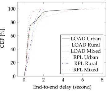
2.3.4 Performance evaluation . . . 39
2.3.5 Summary on routing protocols . . . 42
2.4 RPL in the smart grid networks . . . 43
2.4.1 RPL and Wireless . . . 44
2.4.2 RPL and PLC . . . 48
2.4.3 RPL and heterogeneous networks . . . 49
2.5 Heterogeneous Multiple Interfaces . . . 50
2.5.1 IoT networks . . . 51
2.5.2 Smart Grid networks . . . 51
2.5.3 Conclusion on multi-interface networks . . . 53
2.6 Conclusion . . . 53
iii hybrid framework 3 proposed framework to manage multiple interfaces in rpl 57 3.1 Motivations . . . 57
3.2 Parent oriented design . . . 60
3.2.1 The Parent Oriented concept . . . 60
3.2.2 PO DODAG Formation . . . 62
3.2.3 Conclusion . . . 64
3.3 Interface oriented design . . . 65
3.3.1 The Interface Oriented concept . . . 65 3.3.2 IO DODAG Formation . . . 65 3.3.3 Conclusion . . . 67 3.4 Multiple RPL Instance . . . 67 3.4.1 Heterogeneous RPL Instances . . . 67 3.4.2 MI DODAG Formation . . . 69 3.4.3 Conclusion . . . 69 3.5 Rank computation . . . 70 3.5.1 PO rank . . . 71 3.5.2 IO rank . . . 72 3.5.3 MI rank . . . 72 3.6 Additional mechanisms . . . 72 3.6.1 Link evaluation . . . 73 3.6.2 Retransmission . . . 74 3.7 Conclusion . . . 75 iv practical evaluation 4 evaluation 79 4.1 Design of the implementation . . . 80
4.1.1 Modules and layers . . . 80
4.2 DODAG formation simulator . . . 81
4.2.1 Results . . . 82
4.3 Discret event simulation . . . 85
4.3.1 Simulation scenario . . . 86
4.3.2 Results . . . 87
4.4 Hardware implementation . . . 92
4.4.1 RPL implementation study . . . 92
4.4.2 Unstrung Implementation . . . 93
4.4.3 Hybrid network demonstration . . . 96
4.4.4 Increasing Network Reliability . . . 99
4.5 Conclusion . . . 101
v conclusion 5 conlusion and future work 105 5.1 Conclusion . . . 105
5.2 Perspectives . . . 107
5.2.1 PO improvement . . . 107
5.2.2 Duplication . . . 107
5.2.3 Multiple Instance . . . 108
5.2.4 Large scale scenario . . . 108
5.2.5 Long-term perspectives . . . 108
vi appendix a résumé en français: gestion d’interface multiple dans les réseaux smart grids 113 a.1 Contexte Général . . . 113
Table of Content 3 a.3 Contributions et organisation du manuscrit . . . 117
a.3.1 La gestion d’interface multiple . . . 118 a.3.2 Gestion d’interfaces hétérogènes avec RPL . . . 119 a.3.3 Implémentation et évaluation des performances . . . 121 a.4 Conclusion et perspectives . . . 122
List of Figures
Figure 1.1 The current distribution and transport network topology. . . . 12 Figure 2.1 The current distribution network. . . 22 Figure 2.2 The Data Concentrator in the AMI architecture. . . 24 Figure 2.3 A routing protocol is required to reach the data concentrator. 26 Figure 2.4 Example of a DAG and a DODAG. . . 30 Figure 2.5 Example of an Upward route construction with RPL. . . 34 Figure 2.6 Example of an AODV route detection between node A and G. 37 Figure 2.7 Example of a route construction with LOADng. . . 38 Figure 2.8 End-to-end delay comparison. . . 40 Figure 2.9 RPL Data Delivery Ratio for a 100 nodes topology . . . 41 Figure 2.10 LOAD Data Delivery Ratio for a 100 nodes topology . . . 41 Figure 2.11 100nodes topology to compare LOAD and RPL. . . 42 Figure 3.1 Physical topology of five hybrid nodes. . . 60 Figure 3.2 The Parent Oriented DODAG. . . 61 Figure 3.3 Parent Oriented Parent selection algorithm . . . 64 Figure 3.4 The Interface Oriented DODAG. . . 66 Figure 3.5 Interface Oriented Parent selection algorithm . . . 67 Figure 3.6 Two RPL Instances DODAGs. . . 70 Figure 3.7 The Parent Oriented metric merging for rank computation. . . 72 Figure 3.8 The Interface Oriented metrics for rank computation. . . 72 Figure 3.9 Re-transmission scheme example. . . 75 Figure 4.1 Specifications - module interaction . . . 80 Figure 4.2 Average Link Quality . . . 83 Figure 4.3 Average DAG Depth in hops . . . 83 Figure 4.4 Average number of parents per parent set . . . 83 Figure 4.5 CDF of the number of removed interfaces before the first
parent change . . . 84 Figure 4.6 CDF of the number of parent changes to reach 10% of orphans 84 Figure 4.7 CDF of the number of removed interfaces between two
con-secutive parent changes . . . 85 Figure 4.8 Topology of 11 hybrid RPL nodes . . . 87 Figure 4.9 Average number of parent changes . . . 87 Figure 4.10 Average number of parent changes . . . 88 Figure 4.11 Average end-to-end delay for a one hour time window around
PLC failure. . . 88 Figure 4.12 CDF of the packet delivery ratio. . . 89 Figure 4.13 Packet delivery ratio . . . 89 Figure 4.14 Average number of sent DIO messages. . . 91
Figure 4.15 CDF of the number of hops. . . 91 Figure 4.16 CDF of the rank values. . . 91 Figure 4.17 Average number of re-transmissions. . . 91 Figure 4.18 CDF of the buffer size. . . 91 Figure 4.19 Average number of OF calls . . . 91 Figure 4.20 Root behavior - initialization on ACT with Unstrung . . . 95 Figure 4.21 Node behavior - initialization on ACT with Unstrung . . . 96 Figure 4.22 Testbed topology Meters communicate in PLC and RF. . . 97 Figure 4.23 Format of the frame aggregated at each hop. . . 98 Figure 4.24 Single interface scenario. . . 99 Figure 4.25 Hybrid scenario. . . 99 Figure 4.26 Real-time visualization of the path. . . 100 Figure 4.27 Packet Delivery Ratio (PDR) depending on noise level over
PLC line. . . 101 Figure A.1 Le réseau de distribution et de transport d’énergie actuel. . . 114
List of Tables
Table 2.1 Classification of PLC technologies by frequency range. . . 22 Table 2.2 Alternative technologies to PLC between SM and DC. . . 25 Table 2.3 LOADng / RPL comparison. . . 39 Table 2.4 RPL studies depending on technologies and heterogeneity of
the network . . . 45 Table 2.5 IoT Communication technologies. . . 52 Table 3.1 All supported modulations sorted by capacity. . . 63 Table 3.2 Solution comparison . . . 76 Table 4.1 RDSim Simulation parameters . . . 82 Table 4.2 Simulation parameters . . . 88 Table 4.3 Existing RPL implementations . . . 92 Table 4.4 Comparison between Unstrung and LibRPL . . . 93 Table 4.5 Reliability Experimentation Setup . . . 100 Table A.1 Comparaison des solutions proposées . . . 122
Part I
1
I N T R O D U C T I O NContents
1.1 General context . . . 11
1.2 Background of this thesis . . . 13
1.3 The Contributions . . . 15
1.4 Structure of the Thesis . . . 15
1.1 general context
Over the past few decades, the demand for electricity has faced a tremendous growth, as the life quality has improved and the number of electrical devices are continuously increasing. At the same time, the electricity sector is undergoing a considerable change, mostly by the shifting from fossil to renewable energies, the evolving of energy policies and the emergence of less-reliable renewable micro-generation. As stated in a 2015 Eurelectric survey [Eur15], the grid requires to take into consideration these modifications while ensuring secure, sustainable, competi-tive and affordable energy for any individual and business. Proper operation of the electrical network is based on the balance between production and consumption, a great challenge for the network management. Communication on the power grid has been introduce to automatically collect consumption, diagnostic and status of energy and water metering devices. This technology is deployed by providers to reduce the cost of the trip to reach every device for a reading and for a better management of the grid.
Actually, the grid structure is evolving from a rigid and centralized architecture with large production units at the top satisfying demand at the bottom, to a more distributed one with individual premises equipped with local renewable production units. Electrical production is therefore getting more decentralized but at the same time less predictable as renewable sources are sporadic. In order to efficiently bal-ance production and consumption, real-time measurements, predictions and control capabilities are needed in a widespread management system.
The modifications mentioned above are part of a significant change in an electric system, and more usually, in an energy system which is the focus of the energy transition. As many other countries, France has been developing since 2012 political discussions about the energy transition, and how the french economy could benefit from it. In France, the main challenge of the energy transition is to curb the global warming by, among other solutions, progressively shutdown nuclear sources. A
national debate has been launched in 2012 by the ecology minister in order to address 4 challenges:
• Reduce by 4 or 5 the emission of greenhouse gas until 2050.
• Reduce the part of nuclear at 50% of the total energy mix by 2025.
• Develop the decentralized production of renewable energy.
• Find any form of energy efficiency.
France has introduced a schedule for the energy transition to impose some changes in production, consumption and transport, or even how renewable energies should be chosen. Moreover, a smart grid development has been proposed to the french government in July 2013 [Léo+16].
One of the most important feature of a smart grid infrastructure is the possibility to shift specific electrical consumption; which is expensive, external or have a limited availability; to a cheaper, local or more accessible energy. This feature is notably operated by smart meters, by monitoring all the network, targeting the equilibrium of the energy demand/response.
Furthermore, electrical devices have also quickly evolved in recent years. Some are now mobile such as Electric Vehicles (EVs) making demand prediction more difficult
and increasing the consumption; others, such as building or house automation connected systems (heating/cooling, lighting devices), offer remote management capabilities. Together, their growing numbers, and in particular the increasing penetration ofEVs, make the management of the system even more complex.
GENERATION
TRANSMISSION
DISTRIBUTION
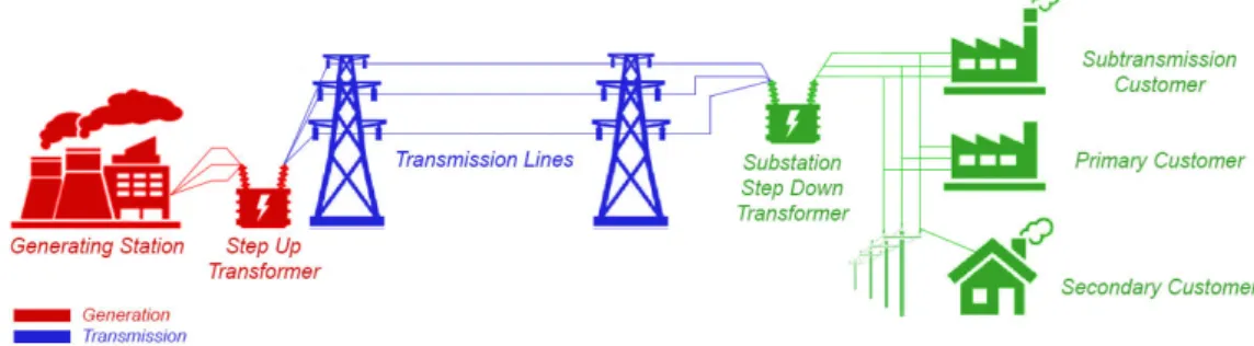
Figure 1.1: The current distribution and transport network topology.
Today, privateEVsare charged as soon as they are plugged into the grid, without any management system, which causes all the charging processes occurring at the same time. This behavior happens mainly at peak hours in the evening, which is very challenging for the electrical grid. Since EVs market is slowly growing, the charging of the few existingEVscan be handled by the actual electrical grid. But, as
1.2 background of this thesis 13
theEVsrate of adoption is increasing [SE11], we will need to avoid charging all of them on peak hours and so, shift these demands on a time window that will contain the needed power below a given threshold, and/or align the consumption on the production periods. As a result, it is essential for the Smart Grid to benefit from a control system that take care of the charging periods to balance the various energy demands over different periods of time.
In Smart Grids, the legacy communication architecture enabling data collection and device management is called the Advanced Metering Infrastructure (AMI) [Bus14, Chap. 7]. This architecture is an evolution of the Automated Meter Reading (AMR) by adding bi-directional communication framework, which was deployed to facilitate meter reading, billing and consumption planning. This two-way communication feature of AMI also offers additional operations on a network. It sure helps the utilities better control their network but several other opportunities are foreseen with such architecture especially if using high-speed Internet Protocol (IP)-based
technologies.
In smart grid communication systems, like other communication systems, we can distinguish a core part and a last-mile1 part. The former involves large storage and computational capabilities used to collect, organize and process data in order to coordinate devices through remote management commands. The latter part consists of uniquely identified and connected objects (e.g., sensors, actuators, smart devices, etc.) as well as communication links between them, possibly by employing various wired or wireless technologies. Energy distribution networks have a tree topology with large production units on top producing most of the required energy, which is then transported via a widespread distribution network towards consumers (called the end-points).
Figure A.1 illustrates this top-down configuration in which consumers can be reached after passing through different aggregating nodes, e.g. transformer. Utilities forecast the consumption of end-points based on their historical consumption and adjust these forecasts based on automated metering. These forecasts are therefore very sensitive to any modification of end-points behavior.
1.2 background of this thesis
The Automatic Meter ReadingAMRuses the Power Line Communication (PLC)
net-work to enable automatic and remote electric and gas meter readings and theAMI
still uses this technology. However, PLC communication networks are subject to
high sensitivity to interference. Errors in suchPLCsystems come especially from
background noise, impulsive noise and Narrow-band Interference (NBI) [Oli+16]. Even-though a MAC protocol could face the high variation of available bandwidth due to the severe noise condition, which is common inPLCnetworks, smart meter
network using onlyPLCfor communication, does not fulfill the primary requirement 1 specifically, last-hop since some radio technologies allow communications over more than ten miles
of 99.99% reading rates and coverage, because of the limitations cited above. Although such a dynamic adaptive solution exists, several alternative communica-tion technologies are considered, such as Wireless Sensor Network, Mesh, cellular, Wimax, Internet of Things (IoT) Long Range, etc. Most of them are also highly
sensitive to noise and may not work in specific environments, those technologies are consequently considered Low power and Lossy Network (LLN).
In order to enhance the communication capabilities, a commonly used solution consists in mixing multiple heterogeneous technologies to cope with all possible scenarios and interference levels. When one technology is not working well in a specific case, most of the time another technology can be used instead. Personal computer Personal Computer (PC), notebooks or even IoT devices are commonly equipped with several heterogeneous interfaces such as Ethernet, Wi-Fi or Bluetooth. A typical example of such a solution in today devices is the smart-phone, embedding commonly at least three different interfaces: Cellular, Wi-Fi and Bluetooth. Each technology having a predefined utility but can be used independently for common services i.e. using Wi-Fi for calling services.
For these reasons, most of future smart meters will embed several heterogeneous communication technologies to ensure a certain quality of service. However, sup-porting these multiple interfaces is a challenge. Most of these technologies are short range, and nodes must collaborate to reach a destination that is multiple hops away. Routing protocols play a central role by optimizing the selected paths according to application requirements and field specificity.
IPv6 Routing Protocol for Low-Power and Lossy Networks (RPL) [Win+12a] is the most popular routing protocol in theIoT community, and included in one of the
most popular Operating System (OS) used inIoT, Contiki OS.RPL is mostly used on
homogeneous network and has been designed to operate on single communication network.
In this thesis, we focus on the wayRPLcould be adapted to work with multiple interfaces and increase the reliability and performance of smart grid communications.
In the state-of-the-art, we can note that only few works have been done on multiple interfaces devices withRPL, since the release of the RFC. Moreover, few works exist also on heterogeneous networks withRPL. Finally, as RPL is mostly studied with
wireless technologies, few works address the specificity of smart gridPLCnetworks,
with a realisticPLC physical model, making complicated the study of large scale smart grid scenario using bothPLCand Wireless interfaces.
1.3 the contributions 15
The goals of this thesis is as follow:
• Propose a framework to extend RPLto handle multiple heterogeneous inter-faces.
• Propose a simulation model to evaluate the performance of the routing solu-tions.
• Implement the framework on hardware platform to test the performance in real condition.
1.3 the contributions
The main contribution of this thesis is the proposition of a multiple interfaces management forRPL. First, this framework propose an original parent selection for
RPLtaking all its interfaces into account. Secondly, the solution aims to increase the
reliability (Packet Delivery Ratio (PDR)) of a hybrid network by encouraging the use
of both available interfaces with a new re-transmission mechanism. 1.4 structure of the thesis
The reminder of this thesis is organized in three chapters. Chapter2presents the context of the thesis and more precisely introduces theAMI, a central point of the Smart Grid. We give an overview of the multiple interface solutions inIoTsystems.
We discuss the characteristics and physical constraints of thePLCnetwork and the
necessity of a routing protocol.
Finally, we present the two major routing protocol families to locateRPLin the
Smart Grid systems.
In Chapter three, we propose a new framework to extendRPLby managing
multi-ple heterogeneous interfaces, in order to increase the reliability and the performance of the network. We develop three solutions, which are the Parent Oriented, the Interface Oriented and the Multiple instance.
We present in chapter four the simulation model we developed to validate our propositions and compare each one.
Chapter five presents the general conclusion of this work and the possible research directions.
Part II
2
M U LT I P L E I N T E R FA C E S I N I O T N E T W O R K SContents
2.1 Introduction . . . 19
2.2 Powerline Communications in Smart Grid . . . 20
2.2.1 PLC protocols for the Smart Grid . . . 22
2.2.2 IEEE P1901.2 . . . 23
2.2.3 The AMI and the challenges of the PLC technology . . . . 25
2.3 Routing . . . 26
2.3.1 Routing requirements and examples . . . 27
2.3.2 Proactive routing protocol . . . 29
2.3.3 Reactive routing protocol . . . 35
2.3.4 Performance evaluation . . . 39
2.3.5 Summary on routing protocols . . . 42
2.4 RPL in the smart grid networks . . . 43
2.4.1 RPL and Wireless . . . 44
2.4.2 RPL and PLC . . . 48
2.4.3 RPL and heterogeneous networks . . . 49
2.5 Heterogeneous Multiple Interfaces . . . 50
2.5.1 IoT networks . . . 51
2.5.2 Smart Grid networks . . . 51
2.5.3 Conclusion on multi-interface networks . . . 53
2.6 Conclusion . . . 53
2.1 introduction
As introduced in the previous chapter, the smart grid is an evolution of the power grid, moving to a decentralized and distributed architecture. This paradigm shift re-quire to make changes in the communications involved in all layers of the transport and distribution network. The energy and environmental challenges are consid-erable, and it forces us to predict the consumption and production of energy in order to maintain the balance of the energy network at various levels. The circu-lation of the energy has to be tackled at neighbors, city, country and worldwide scale. The Smart Meter (SM) plays a major role in this evolution, since it allows to finely
read the consumption of housing, business and industry activities. It has control and measure capabilities as well, that is necessary to handle cut-offs and shifting of energy demand.
However, the distance and density betweenSMvaries significantly depending on location (Urban, Rural, Industrial) and the employed communication technologies are not fully reliable. Consequently, it is required to duplicate the communications technologies in order to be more reliable, and deploy standardized protocols to allow the use of routing solutions.
Section2.2introduces thePLCprotocols in the Smart grid and why it has been selected as a candidate technology to be used inAMInetworks. Section2.3introduces
the necessity of routing technology in the Smart grid, and presents in details the two major routing protocols used in Smart grid networks. In2.4we discuss the existing work on RPL in a smart grid network. Finally, section 2.5 presents the different
solutions of multiple interfaces in communication networks, focusing on theIoTand
the smart grid community and also discusses the related work regarding routing with multiple homogeneous and heterogeneous interfaces in smart grid networks. 2.2 powerline communications in smart grid
Today electricity network is organized with the following principles:
A generating station produces electricity from fossil, nuclear, or renewable energy, and this electricity is transported at High Voltage (HV) to the substations via a transmission network. The substations has the role of step-down, via transformers, it lowers the voltage to distribute the electricity to the final consumer, at a Medium Voltage (MV) or Low Voltage (LV).
In order to reduce the cost of generation and conversion at the power generation level, a distributed generation approach [Gre+14] [Mül+10] tackles the conventional power plant process by mixing energy sources. Such an approach facilitate the exploitation of the renewable energy resources.
The implementation of distributed generation involves several and complex de-ployments such as wind turbines, photovoltaics, or micro-turbines. This model imposes communication between all components to manage the energy demand, and must be related to automatic generation control and demand forecasting to meet the demand of consumers.
At the transmission and distribution level, the distributed generation model including renewable energy sources causes some challenges regarding reliability. To integrate energy sources that are mainly based on renewable production, the electricity network needs a control strategy. The intermittent profile of renewable energy sources caused by the unstable and unpredictable climate change, need to be addressed in order to avoid frequency, voltage and power fluctuations. Using enhanced measurement, information and control techniques on the distribution ad transmission grid allows to respond quickly or anticipate failures and make the network more reliable.
2.2 powerline communications in smart grid 21
Phasor measurement unit (PMU) is one of the most used measurement techniques that is installed and is being deployed widely. The purpose ofPMU is to monitor
the phasor synchronizations, the voltage stability, the load sharing, and power flows [RAB13]. It detects the faulty lines and decides the islanding requirements (when for instance solar panel still deliver power even though being in a power outage), restore the power systems, and so on.
At the distribution level, the required management system is complex, because it has to handle the continuous development of renewable energy sources, theEV,
smart home application and energy storage. For example, the massive introduction of theEVin the electricity grid will pose some challenges:
• It involves bidirectional power flow with the Grid to Vehicle (G2V) and Vehicle to grid (V2G) systems [YK13],V2Gbeing an operation mode that is a concept of considering the EV as a battery that can supply electrical energy to the
grid. Most of electricity applications is focusing on customer energy providing, going in the opposite way impose drastic changes on the grid control.
• The EV charging need a high availability and intensity of power as quick charging mechanism is a key point ofEVattractiveness. Charging require to be adaptable as well, charging station has different mode of operation that increase the complexity of the energy supply.
• The democratization of theEVtends to create a peak hour, when a majority ofEVusers need to charge at the same time after work or during night. This problem needs to address the question of anticipation and/or prioritization of demand.
Control and communication solutions are not equally deployed in the former architecture. The transport network is more equipped than the distribution network, with high speed communication devices to enable the supervision and the control of the network with the Supervisory Control and Data Acquisition (SCADA). TheSCADA
system consists of several automation devices to control and monitor the electricity network components, such as Remote Terminal Units (RTU) at transport and
distribu-tion level, to collect real-time data at a relatively low granularity (up to 10 samples/s). At the distribution level, the former power grid only allowed to collect limited information from the consumer, and only in one-way. Consequently, the facility cannot manage the load of the customer and can only make an estimation, the consumer cannot have any influence on the network behavior.
A second and major challenge of the actual electricity network is the consequence of not knowing in real-time the demand of electricity from consumers. To avoid blackout, the energy is provided and maintained with the maximum estimated consumption. Knowing with high precision where and when the charge will occur could allow provider to better shift and smooth consumption.
Figure 2.1: The current distribution network. Categories Frequency
Range
Data Rates Application Ultra Narrow Band PLC
(UNB-PLC)
0.3 to 3kHz Hundreds Bps AMR, Utilities
automation. Narrow Band PLC
(NB-PLC)
3to 500 kHz up to 500 kbps AMI, Smart grid
Broadband PLC(BB-PLC) 1.8 to 250 MHz
up to hundreds Mbps
Data, Multimedia Table 2.1: Classification of PLC technologies by frequency range.
The age of the electricity network and the constant rise in electricity consumption impose to strengthen the electricity network and manage it in a smart way. But im-proving the electricity network is not economically and ecologically feasible, that is why the distribution must evolve with smart architecture and device on the existing infrastructure.
Since the beginning of the communication in the electricity network, the Power Line Communication (PLC) technology has been employed and still meet the require-ments of today metering applications. It has been chosen as a key technology of the smart grid development as well [Gun+13]. But thePLCtechnology, presented in the
next section, has reached some limits in terms of reliability and delay. The last-mile of theAMInetwork, wherePLCfaces most of the challenges, needs to be modernized to
be managed in a smart way to accommodate, in particular, the smart meters network.
2.2.1 PLC protocols for the Smart Grid
Three different types ofPLCexist according to the frequency range used, table2.1
shows the classification of thePLCtechnology by the frequency band.
Ultra Narrow Band (UNB) PLC operates at Ultra Low Frequency (0.3-3kHz) band
2.2 powerline communications in smart grid 23
operate trough long distances, over 150 km. For decades, it has been used forAMRor automation systems for distributed facilities, an example of suchUNB-PLC solution
is the Two-Way Automatic Communication System (TWACS) [MM84; MR82], a patented technology to transmit data over power lines for collecting, communicat-ing, and analyzing information and managing utility customer electricity usage.
UNB-PLC has many advantages such as the cost, the communication range, the
maturity of the technology, or the scalability, but non standard solution exists today, allUNB-PLC solutions deployed by utilities are proprietary.
Narrow Band (NB) PLC operates at Very Low Frequency, Low Frequency and Medium Frequency bands (0.3 to 500kHz) with a data rate from few kbps to 500 kbps. The range ofNBPLC is at maximum several kilometers. According to Scaglione
et al. [GSW11], we could separate theNBPLC standards in two categories:
• Low Data Rate (LDR): Several standards exist such as ISO/IEC 14908-3 (Lon-Works), ISO/IEC 14543-3-5 (KNX), CEA-600.31 (CEBus), IEC 61334-3-1, IEC 61334-5 (FSK and Spread-FSK), etc. Based on single carrier technologies, these standards are capable of data rates of few kbps.
• High Data Rate (HDR): G3-PLC, ITU-T G.hnem, and IEEE P1901.2 are typical examples of HDR NB PLC. Based on multicarrier technologies, such as Orthog-onal Frequency Division Multiplexing (OFDM), those solutions are capable of data rates from tens of kbps to 500 kbps.
Broadband (BB) PLC operates at High / Very High Frequency (1.8 to 250 MHz)
band with a high data rate from several Mbps to several hundreds of Mbps. The transmission range ofBB-PLC technologies is limit to hundred meters, making it most suitable for Home Area Network (HAN). TIA-1113 (HomePlug 1.0), IEEE 1901,
ITU-T G.hn (G.9960/G.9961) are the most common standard recommendations used to conformBB-PLC devices.
In the electricity distribution network, from the generation to the consumer, all types of PLC could be deployed. AMI applications have data rates and range requirements that explain why NB-PLC is gaining interest and standardization
efforts.
2.2.2 IEEE P1901.2
IEEE P1901.2 is one of the most deployed standard in smart grid networks. It is a
NB-PLC standard that uses Orthogonal frequency-division multiplexing (OFDM) and can support two modulations schemes:
• A mandatory Differential mode modulations: Differential Binary Phase Shift Keying (DBPSK), Differential Quaternary Phase Shift Keying (DQPSK) and Differential Eight Phase Shift Keying (D8PSK).
Both modes have a default robust modulation, the Robust Orthogonal Frequency Division Multiplexing (ROBO).
In smart grid networks, a MAC protocol is required to face the high variation of available bandwidth due to the severe noise condition, which is common inPLC
networks.
The MAC layer of IEEE P1901.2 is based on the IEEE 802.15.4 MAC with a similar frame structure and manage the channel access thanks to Carrier Sense Multiple Access with Collision Avoidance (CSMA/CA) with a random back-off time. This back-off time is used to reduce the probability of collisions, devices wanting to transmit a frame need to wait a random period before transmission if the channel is idle. TwoCSMA/CAmodes are defined for IEEE P1901.2, an unslotted version based on IEEE 802.15.4 and a slotted version, dedicated to beacon-enabled Premise Area Network (PAN).
IEEE P1901.2 define an Inter Frame Spacing (IFS) that is needed between frames in order to face propagation and processing time. Depending on frame type, three different time interval (IFS) are used to ensure that frames do not overlap each other. Finally, IEEE P1901.2 uses the Tone Map mechanism to determine the modulation to use on a link depending on the quality. A frame is sent with the default mod-ulation and the receiver will estimate the communication link to define the PHY parameters to use.
2.2 powerline communications in smart grid 25
Wired (Fiber Optic) GPON, EPON RFoG-DOCSIS Wireless 802.16d/e (Wimax) 802.15.4g (RF Mesh) 802.15.4 (ZigBee) 802.11 n/g (WLAN) RF Radio Pto-Mtp/MAS 3G-3GPP/1XRTT/EVDO GPRS/EDGE/HSDPA Table 2.2: Alternative technologies to PLC between SM and DC. 2.2.3 The AMI and the challenges of the PLC technology
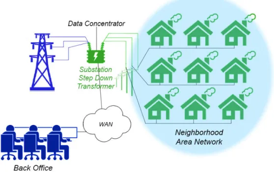
As depicted in figure2.2, the Advanced Metering Infrastructure (AMI) is a key part
of an intelligent grid where the Data Concentrator (DC) allows to connect Smart Meter (SM) to the utilities Meter Data Management Systems (MDMS) [RM11]. It allows
two-way communication between smart meters and the distribution system operator, in order to automate the collect of user energy metering and billing [BMM12]. In most of the Europe countries,AMRinfrastructure is widely deployed, and European
directive have been set to target 80 per cent of customers having electronic meter at the end of 2020 [Bol+11]. The Linky program [DGF13] follows this directive in France, the french operator ERDF targets to install 35 million of Linky electronic meters in customer’s premises.
Generally, theSMare installed in the Neighborhood Area Network (NAN) close
to the customer and communicate with the Data Concentrator (DC) usingPLC
tech-nology. The DC could be viewed as a gateway between the Utilities (Wide Area Network (WAN)) and theNAN.
PLChas several advantages such as:
• The existing infrastructure, offering a low cost deployment.
• The potential location ofSMthat could not be compatible with wireless solu-tions, i.e. behind concrete or metal walls.
• ThePLCnetwork is the property of the utilities and it has a full control on it , instead of wireless network that uses public frequency band.
However,PLCfaces several issues related to noise and interference, which makes PLCtechnologies not fulfill the primary requirement of 99.99% reading rates and coverage. Indeed, OFDM-based narrow-bandPLCsystems are weakened by
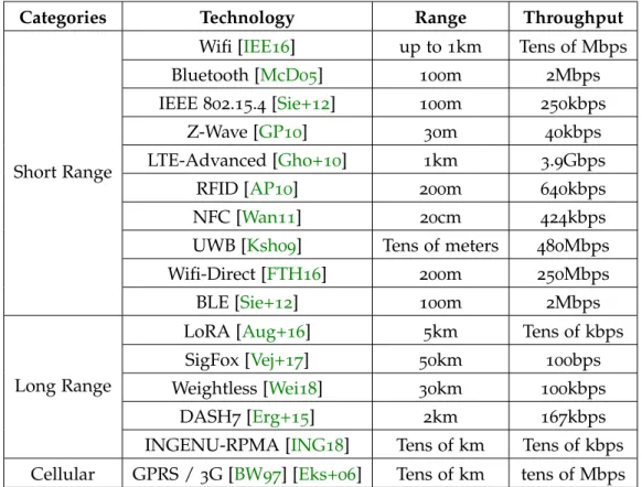
Several other technologies thanPLCexist in smart grid networks to connectDC
andSM, as shown in table2.2.
2.3 routing
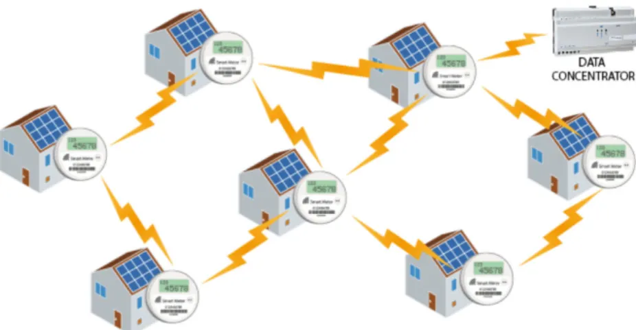
In smart grid networks, the majority of smart meters are located in theNAN, but due to the distance, the signal cannot reach directly the Data Concentrator (DC), located
in the transformer substation. Consequently, a forwarding is necessary to reach the destination, and a routing is required to compute the path fromSMto the sink, and vice versa (Figure2.3).
Figure 2.3: A routing protocol is required to reach the data concentrator.
As it was presented in Section2.2.3,AMInetworks mostly utilize technologies that
are sensitive to perturbation and have limited capacity. This technologies could be considered asLLNs.
In a dense network, if a relay node is not reachable, the transmitting node needs to choose a different neighbor to reach the destination, that is why routing is necessary. InNB-PLC and wireless networks, most of the nodes that exist in the infrastructure
cannot communicate directly with the sink or with other nodes due to the limited transmission capacity (long distance, external interference and noise). Therefore, the nodes need to collaborate together to forward the data packets to the final destination. Similarly, in a smart grid network, the nodes are the Smart Meter (SM)
that route metering information to the Data Concentrator (DC).
Typically, a routing protocol constructs and maintains the best paths in the net-work for the packets to be routed toward the destination. To do so, routing protocols propagate routing information message using either proactive or reactive models.
High number of hops degrades the network performance as it introduces addi-tional delay in reactive routing or addiaddi-tional overhead in proactive approaches. To
2.3 routing 27
minimize the impact of routing, it is essential to minimize the number of hops in the network. However, it is also important to carefully select the optimal path to the destination according to an objective function and appropriate metrics. Note that the shortest path is not always the optimal solution, i.e., the Expected Transmission Count (ETX) is a popular metric in IoTnetworks.
In the next section, we introduce the requirements of the routing protocols in Low power and Lossy Network (LLN), focusing on smart grid networks.
Following that, in section 2.3.2 and 2.3.3 we provide a detailed description of two leading families of routing protocols, based on the propagation of the routing information in the network, namely the proactive and the reactive routing protocols, respectively.
In smart grid networks, mainly two routing protocols are emerged, and are widely studied and deployed. J.Yi et al.[JCI13] present how critical the routing protocol is for smart grid networks, and howRPLand Lightweight Ad hoc On-demand
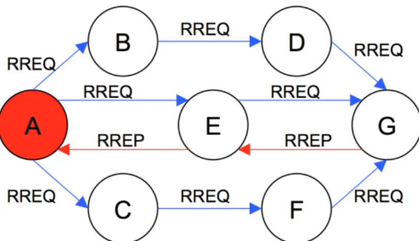
Distance-vector Routing Protocol Next Generation (LOADng) could tackle the specifics of
smart grid applications. Moreover, we present a performance comparison of the most popular routing protocols such asRPL, Ad Hoc On-Demande Distance Vector
Protocol (AODV) andLOADngforLLNs.
2.3.1 Routing requirements and examples
Since the 80’s, several routing protocols have been proposed and studied for wireless multi-hop networks. These protocols have been envisioned to be composed of mobile nodes without concerns on energy. In 2008, the IETF ROLL working group has been created to standardize a routing protocol that address the issues of a Low power and Lossy Network (LLN). The ROLL approach is to consider static node with high
energy-constrained characteristics.
Levis et al. show in [TD09] the requirements of a routing protocol designed for
LLN, such as the scalability. For example, a routing state that scales linearly with the
number of nodes would not be appropriate. Culler et al. [VC07] recommend for the routing protocol to be robust to high variation in connectivity.
These protocols need to use specific routing metrics that deal with the characteris-tics ofLLN. For instance, the link reliability metric is not used in the Internet routing
protocols because technologies employed in such networks are extremely reliable and fast recovery mechanisms exists for failure. But inLLN, taking into account the reliability of the links to build the path is significant because link quality quickly changes over time.
In addition, using the node’s energy consumption as a metric allows to consider how the node is powered and what is its remaining lifetime. Such metric is a
key-enabler to enhance the lifetime of a wireless network where devices are mostly battery-operated.
Moreover, a routing protocol forLLNhas to use a minimum overhead to discover and maintain the topology and must adapt to the network variations without drasti-cally increase control messages.
Finally, routing protocols have the role of avoiding loops in the network, the routing algorithm must guarantee that loops can never happen by the use of ranking mechanisms or number sequences.
InAMInetworks, the majority of the existing routing protocols are focusing on
reliability, and automatic neighbors and routes discovery. Smart grid applications are deployed in harsh environment, where links are unstable because of interference and fading effect. We can identify three approaches to address this problem in the community:
• Providing efficient repair mechanism
• Using a multipath algorithm
• Anticipation of the fluctuation by metric modification
There are many routing protocols that are deployed and studied in the smart grid, Saputro et al. [SAU12] propose a survey that covers both transport and distribution networks of the smart grid, and a focus on the Neighborhood Area Network (NAN). Two examples of routing protocols used inAMIapplication are presented below.
Distributed Autonomous Depth-First Routing (DADR) [Iwa+10] is a distance vector routing protocol but without any repair mechanism for the computed path. The protocol avoids the frequent control overhead required for path maintenance in proactive routing protocols to provide a lightweight routing plane. It only uses periodic HELLO messages that are exchanged only among neighboring nodes. This control message contains routing table information and allows to provide at most k possible paths for destination.DADRalso propose a backtracking mechanism when all next hops fails, the packet is returned back to the previous sender, as it can try, at its turn, all alternate routes. This mechanism could lead to loops problem, a loop detection allows to discard messages based on an identifier (FID) and inform others nodes by route poisoning that a loop exists.
The protocol evaluation reveals good performance on control packets num-ber, which outperforms both AODV and Optimized Link State Routing
Proto-col (OLSR)[Iwa+10]. The authors show a good scalability ofDADRwith a real
deploy-ment of 1500 nodes and a 2107 nodes simulation experideploy-ment. However, the particular process ofDADRduring forwarding phase impose more memory and CPU overhead
2.3 routing 29
HYDRO [DTC10] is a link-state routing protocol forLLNthat use a distributed algorithm to form and maintain a distributed Directed Acyclic Graphs (DAG). This
routing graph provides multiple paths to a border router, providing a reliable default route at each node by selecting a neighbor node toward the border router. HYDRO requires the collection of topology information from the network, in order to have a complete view of the topology by the border router. To do so, each node periodically sends a topology report to the border router, containing only top ranked entries in the default route table.
The topology information is added opportunistically to data traffic with an op-tional extension header. In [DTC10], a simulation of 125 nodes is conduct to show how the default route provided by HYDRO is reliable and robust, with aPDR
re-maining near 98.7% at the end of every scenarios where four random nodes are removed in the topology every four minutes. It has to be noted that HYDRO could support multiple border routers to duplicate the main border router and have the same global view of the topology.
2.3.2 Proactive routing protocol
In proactive routing protocols, routes are built a priori and, as a result, all nodes in a network are aware of the routes to any destination at any time. Thus, a node may transmit a data packet to any destination independently of the traffic with no delay, since routes should be stored in the routing tables.
Periodic routing-related control packets need to be transmitted to maintain the routing table up-to-date. To control the network overload and mitigate the number of control packets, the periodicity at which these control packets are sent must be accurately defined.
RPL[Win+12b] is today the main protocol in the proactive family of routing
proto-cols chosen inLLN. It is actually a distance vector routing protocol specified by the Internet Engineering Task Force (IETF) ROLL working group [ABC14].RPLis defined
as Link-layer agnostic, so it can operate over Wireless orPLCnetworks for example.
Topology management under RPL
RPLdefine mechanisms to led nodes discover themselves and carefully select neigh-bors in order to construct optimal routes. The topology is organized based on aDAG,
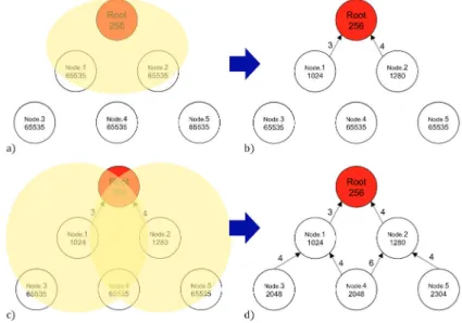
a graph where the connections between nodes have a direction and a "non-circular" property. Based on the "acyclic" nature of theDAG, the graph comprises at least one root, a node with no outgoing edge. In Figure2.4(a), aDAGcomposed of ten nodes
Figure 2.4: Example of a DAG and a DODAG.
To construct a routing topology,RPLemploys an extension ofDAG: the Destination
Oriented DAG (DODAG) which is a DAG with a single DAG root. In a smart grid
scenario, the root of aRPLnetwork could be the data concentrator that gathers the metering information. Figure2.4(b) depicts aDODAGtopology that consists of eight
nodes with one root.
To establish and maintain routes,RPLuses three different types of ICMPv6 control
packets:
• DAG Information Object (DIO) • DAG Information Solicitation (DIS) • Destination Advertisement Object (DAO)
The upward route construction, the one used between smart meters and the core network, is managed by transmittingDIOmessages in multicast.DIOmessages
contain information that allows discovering aRPLinstance, calculating its own rank
and choosing parents in theDODAGtoward the root. The rank contained in the DIO message is the rank of the node sending theDIOmessage and determines the relative
position of a node in theDODAG. The rank is computed by an Objective Function
using routing metrics to represent the distance of a node from the root. The closer a node is to the root, the smaller its rank is. To avoid loops, a node can only choose as a parent a node with a smaller rank. A node could have multiple potential parents, it groups these neighbors in what is called a parent set. The potential parent offering the smallest rank among all parent in the parent set is the preferred parent. The preferred parent is the next hop of node.
The downward route construction, which is optional in RPL, is managed by the
DAOmessages to propagate information about the destination in the upward
2.3 routing 31
In Non-Storing mode of operation,RPLroutes messages downward using IP source routing. In Storing mode operation,RPL routes messages downward by the IPv6
destination address.
Finally,DIScontrol packets are used to solicit aDIOmessage from aRPLnode.
It has to be noted that in all of our implementations, we useRPLin Storing mode.
Routing table maintenance under RPL
As previously stated,DIOmessages are periodically transmitted to build and
main-tain theRPL DODAG. However, if the network is stable, theDIOmessage frequency is decreased to reduce the overhead of signaling messages. On the contrary, if the condition of the network is not stable, moreDIOmessages have to be transmitted.
This timing function is called Trickle timer [Lev+11]. If a receivedDIOmessage does not imply any change on the receiver in terms of rank, parent set or preferred parent, theDIOis considered consistent. As long as consistent messages are received, the
interval betweenDIOmessages is exponentially doubled to reduce the overhead of periodic messages.
Conversely, when the network is not stable and DIOmessages are inconsistent with the known topology, moreDISandDIOmessages are needed to update the node
routing tables. Messages such as multicastDISwithout a solicited information option
orDIOmessages containing infinite rank are considered inconsistent, and cause the trickle timer to reset, and the interval time is set to its minimum value. The Trickle algorithm allows to be reactive in case of a change or failure in the network while minimizing the overhead when the network is stable.
For the downward route construction, a DelayDAO is sent to govern the emission of theDAOmessages. At each transmission of aDAO message, a random interval is chosen before the actual transmission.
Routing strategy: metrics and constraints
A metric inRPL is a quantitative value, used to evaluate the path cost. Vasseur et
al. [Vas+12a] define two kinds of metrics that can be used for path calculation: • The link metric that concerns the link’s attributes e.g., Link Quality Level (LQL),
ETX, latency, throughput.
• The node metric that takes into account the Node State and Attribute (NSA) such as energy (remaining energy, power source) or min-hop (number of hops to the root).
RPLsupports also a constraint-based routing where a constraint may be applied on
from the parent set.
This constraint is used to include or eliminate a link or a node that not meet a specific criteria. For instance, the Objective Function will not select a route that traverses a node that is battery-powered or a link with lowETX. A RPL Objective
Function could combine metrics and constraints to select the best parent.
Path computation under RPL
The way a parent is selected is independent fromRPLand rely on a defined Objective
Function. To provide optimal routes, an Objective Function plays a major role inRPL. To this aim, the two following algorithms have to be defined:
• the computation of the node’s rank according to one or several metrics
• the parent selection operation according to metrics and constraints
Two objective functions have been defined by the ROLL working group: Objective Function Zero (OF0) and Minimum Rank with Hysteresis Objective Function (MRHOF) that are presented next.
the objective function zero TheOF0[Thu12] computes the rank based on
the rank of the parent with the addition of a scalar, representing the link properties with the parent. The scalar value is normalized between 1 and 9 for expressing the link properties with 1 for excellent, and 9 for very poor. Note that any kind of metric could be used for the scalar value.
This objective function allows for finding the closest grounded root (a root that offers connectivity to the application goal) by selecting a preferred parent and po-tential parents in a parent set.
The rank computation is given by the equations2.1and2.2below: (2.1) R(N) =R(P) +rank_increase
(2.2) rank_increase= ((R f ∗Sp+Sr) ∗MinHopRankIncrease)
where:
• R(P) is the preferred parent’s rank
• Sp (the step_of_rank) is the expression of the link properties normalized between 1 and 9
• Sr (stretch_of_rank) is the maximum augmentation to the step_of_rank of a preferred parent to allow the selection of additional potential parents in the parent set
2.3 routing 33
• Rf (rank_factor) is a value used to increase the importance of the link properties.
• MinHopRankIncrease is a multiplying factor that plays a major role in the rank computation by reflecting the impact of the metric on the rank increase. The default value is 256 as it is described in[Win+12b].
OF0parent selection is governed by several rules (see Section 4.2.1 of [Thu12]), but
the most important is that the selected parent must be the one that causes the lesser resulting rank for the node.
the minimum rank hysteresis objective function MRHOF[GL12] opti-mizes the path to the root that miniopti-mizes a defined metric.
MRHOFworks with additive metrics and introduces the path cost for the rank
com-putation, that specifies the property of the path to the root regarding the employed metric. The path cost is calculated by the sum of the path cost advertised by the parent and the link metric cost to the parent.
The rank computation forMRHOFis given by the algorithms2.3and2.4below: (2.3) path_cost= parentpath_cost+link_cost
(2.4) rank= f unc(path_cost)
where:
• parentpath_cost is advertised by the parent and represents the path cost of the parent.
• link_cost is the cost associated with the link with the parent regarding the selected metric.
MRHOFparent selection is governed by an hysteresis function, in order to handle
light metrics variations that could lead to frequent parent changes.
This hysteresis function is given by the equation2.5where P1path_costand P2path_cost are respectively the path cost to Parent 1 and Parent 2. PP is the selected parent designated as Preferred Parent. P1 is the current best parent and P2 is a candidate parent.
(2.5) PP=
P2 i f P1path_cost+Threshold> P2path_cost
P1 else
where Threshold is the hysteresis function, i.e., the minimum difference between the cost of the path through the preferred parent and the path cost of a candidate parent to trigger the selection of a new preferred parent.
Figure 2.5: Example of an Upward route construction with RPL. Summary of the RPL DODAG construction
Figure2.5shows an example of the upward route construction using theETXas the
metric. Once the trickle timer is expired, theRPLroot will broadcast aDIOmessage, containing its rank. Nodes in the coverage area of the root (i.e., yellow circles) will receive theDIOmessage and process it. If theDIOmessage had been corrupted, it would have been discarded. Node 1 and 2 have a rank equal to the in f inite_rank value, when receiving theDIOfrom the root, as the rank of the root is smaller than
the in f inite_rank value, node 1 and 2 will choose the root as the their preferred parent and compute their rank.
To test if the root is eligible to be a preferred parent, node 1 and 2 will verify if the rank contained in the receivedDIOmessage from the root added to aRPLparametric
value (min_hop_rank_increase) is less than their rank.
The arrows between nodes represents the upward route and when a node installed at least one route, it is considered to have joined theDODAG. It has to be noted that a
node may either stay silent and wait for aDIOmessage or it may send aDISmessage during the initialization process.
Then node 1 and 2 will broadcast their ownDIOmessage with their new computed rank. Note that since the root has a smaller rank than the one advertised in nodes 1 and 2DIOmessages, nodes 1 and 2 will not be considered as potential parents for
the root. It is worth mentioning that ranks shown under node names in this example depends on the objective function and values shown beside edges representing the link quality (i.e.,ETX).
ThisRPLintroduction shows how a proactive routing protocol could be