MODÉLISATION ET SIMULATION DE PYROLYSE DE PNEUS USAGÉS
DANS DES RÉACTEURS DE LABORATOIRE ET INDUSTRIEL
JEAN-RÉMI LANTEIGNE
DÉPARTEMENT DE GÉNIE CHIMIQUE ÉCOLE POLYTECHNIQUE DE MONTRÉAL
THÈSE PRÉSENTÉE EN VUE DE L’OBTENTION DU DIPLÔME DE PHILOSOPHIAE DOCTOR
(GÉNIE CHIMIQUE) JUIN 2014
UNIVERSITÉ DE MONTRÉAL
ÉCOLE POLYTECHNIQUE DE MONTRÉAL
Cette thèse intitulée :
MODÉLISATION ET SIMULATION DE PYROLYSE DE PNEUS USAGÉS
DANS DES RÉACTEURS DE LABORATOIRE ET INDUSTRIEL
présentée par : LANTEIGNE Jean-Rémi
en vue de l’obtention du diplôme de : Philosophiae Doctor a été dûment acceptée par le jury d’examen constitué de : M. TAVARES Jason-Robert, Ph.D., président
M. CHAOUKI Jamal, Ph.D., membre et directeur de recherche M. DOUCET Jocelyn, Ph.D., membre
DÉDICACE
À ma merveilleuse épouse, Katia
REMERCIEMENTS
Je voudrais tout d’abord remercier mon directeur de recherche, le professeur Jamal Chaouki. Il m’a toujours poussé à me dépasser, à sortir de ma zone de confort. Durant les méandres de mon parcours doctoral, il a fait preuve d’une grande compréhension. Je lui suis reconnaissant et je me considère privilégié d’avoir pu faire partie de son équipe de recherche.
Je tiens à souligner la grande collaboration de Jean-Philippe Laviolette. Jean-Philippe m’a conseillé judicieusement au cours de la rédaction et a travaillé très fort pour assurer la qualité des publications. Merci pour ta patience et ton temps précieux.
RÉSUMÉ
La présente thèse couvre une étude appliquée sur la pyrolyse des pneus. L’objectif global est de développer des outils pour permettre la prédiction de la production et de la qualité de l’huile de pyrolyse des pneus.
Le premier objectif de recherche consistait à modéliser la cinétique de pyrolyse des pneus dans un réacteur, en l’occurrence un tambour rotatif industriel opérant en mode batch. Une revue de littérature effectuée ultérieurement a démontré que la quasi-totalité des modèles cinétiques développés pour représenter la pyrolyse des pneus ne parvenait pas à représenter avec suffisamment de précision le procédé industriel à l’étude.
Parmi les familles de modèles cinétiques pour la pyrolyse, trois ont été identifiées : modèle à une seule réaction globale, modèle à plusieurs réactions parallèles combinées linéairement et modèle à plusieurs réactions en série et/ou en parallèle. Il a été remarqué que ces modèles ont des limites. Dans les modèles à réaction globale et à plusieurs réactions en parallèle, la production de chaque produit pyrolytique individuel ne peut être prédite, mais seulement pour les volatiles combinés. De plus, le terme massique de la cinétique se réfère à la quantité de char finale (W∞), qui varie en
fonction des conditions de pyrolyse, ce qui rend ces modèles beaucoup moins robustes. Aussi, malgré le fait que les modèles à plusieurs réactions en série et/ou parallèle puissent prédire le taux de production de chaque produit de la pyrolyse, les sélectivités sont déterminées pour des températures d’opération et non des températures réelles de masse, ce qui génère des modèles dont l’ajustement des paramètres fait défaut lorsqu’utilisé à l’échelle industrielle.
Un nouveau modèle cinétique a été développé, permettant de prédire le taux de production de gaz non-condensable, d’huile et de char provenant de la pyrolyse des pneus. La nouveauté de ce modèle est la considération des sélectivités intrinsèques de chaque produit en fonction de la
température. Cette hypothèse a été considérée valide assumant que dans le procédé industriel de pyrolyse, la cinétique de pyrolyse est limitante.
Le modèle développé considère des cinétiques de production individuelles pour chacun des trois produits pyrolytiques proportionnelles à une cinétique de décomposition globale des pyrolysables. Les simulations avec des données obtenues en opération industrielle ont démontré la robustesse du modèle à prédire avec précision en régime transitoire, la pyrolyse des pneus, à l’aide de paramètres du modèle obtenus à l’échelle du laboratoire, nommément en ce qui a trait au début de la production, le temps de résidence des pneus (production dynamique) et de la quantité d’huile produite (rendement cumulatif). Il s’agit d’une toute nouvelle façon de modéliser la pyrolyse qui pourrait être extrapolée à de nouvelles matières premières.
Le deuxième objectif de cette recherche doctorale était de déterminer l’évolution de la chaleur spécifique des pneus pendant la pyrolyse et l’enthalpie de pyrolyse. L’origine de cet objectif provient d’une contradiction primaire. Outre quelques exceptions, il est admis que la pyrolyse des matières organiques est globalement un phénomène endothermique. À l’opposé, toutes les expériences menées à l’aide d’appareils de laboratoire tels la DSC (Differential Scanning Calorimetry) ont montré des pics exothermiques durant les expériences dynamiques (rampe de température constante). Cela a été confirmé par les résultats obtenus à l’échelle industrielle, où aucune trace d’exothermicité n’a été observée. La loi de Hess a aussi confirmé ces résultats, à savoir que globalement, la pyrolyse est bel et bien un processus entièrement endothermique. Un bilan d’énergie précis est requis pour prédire la température des pneus durant la pyrolyse, paramètre indissociable de la cinétique.
Une investigation approfondie du char a permis dans un premier temps de démontrer que la chaleur spécifique des solides au cours de la pyrolyse décroît en fonction de la température jusqu’à l’atteinte du pic de perte de masse en décomposition, vers 400°C, pour ensuite remonter. Ce constat, combiné au fait que l’échantillon perd de sa masse au cours de la pyrolyse est
considéré comme la principale cause de l’apparition du pic exothermique dans les expériences de laboratoire. C’est-à-dire que le système de contrôle de ces appareils provoque un biais et une surchauffe involontaire des échantillons leur conférant un comportement exothermique. Il s’agirait donc d’un artéfact.
Sur la base des nouvelles données sur l’évolution de la chaleur spécifique globale en pyrolyse, un modèle du bilan d’énergie a été développé à l’échelle industrielle pour déterminer l’enthalpie de pyrolyse. La simulation a montré que la majeure partie de la chaleur transférée à la masse décomposée servait à augmenter sa température. Ensuite, une enthalpie de pyrolyse dépendante de la perte de masse a été obtenue. Enfin, deux autres termes d’enthalpie ont été trouvés, nommément une enthalpie pour le bris des ponts soufrés et une enthalpie pour la stabilisation du char lorsque la conversion approche la complétion.
Cette recherche aura permis d’établir une nouvelle méthodologie générale pour déterminer l’enthalpie de pyrolyse. Plus particulièrement, de nouveaux éclaircissements ont été obtenus quant à l’évolution de la chaleur spécifique de la masse lors de la pyrolyse et de nouvelles enthalpies de pyrolyse, toutes endothermiques, ont pu être obtenues, en accord avec les attentes théoriques.
Le troisième objectif de recherche concernait le comportement du soufre lors de la pyrolyse des pneus. Avec comme prémisse que le soufre est un contaminant intrinsèque de plusieurs résidus à valoriser, il est critique d’en clarifier le devenir lors de la pyrolyse, dans le cas présent des pneus usagés. De la littérature est ressorti que certaines analyses quantitatives avaient été présentées, mais de façon généralisée, les mécanismes de distribution du soufre parmi les produits pyrolytiques demeurent flous. Ainsi, il n’était pas possible de prédire le transfert du soufre vers chacun des produits de la pyrolyse des pneus.
Les résultats tirés de la littérature ont été complémentés par une série d’expériences en TGA, suivies d’analyses élémentaires complètes pour les résidus solides. Des bilans de matière ont été effectués afin de caractériser la distribution des différents éléments parmi les trois produits (gaz non-condensable, huile et char). Un tout nouveau paramètre a été créé lors de cette recherche : la sélectivité pour la perte du soufre. Cette sélectivité intrinsèque est une prédiction de la répartition du soufre dans les produits de la pyrolyse en fonction de la température.
Trois phénomènes ont été identifiés pouvant affecter la sélectivité pour la perte du soufre. Tout d’abord, la volatilisation naturelle du soufre due à la pyrolyse. Ensuite, la volatilisation du soufre due à la désulfuration de la matrice solide par l’hydrogène et enfin, la séquestration du soufre à l’état solide due à la sulfuration des métaux (zinc et fer). Les résultats ont démontré que cette sélectivité atteint la valeur limite de 1 dans des conditions où la pyrolyse est limitée par la cinétique et en l’absence de métaux. Lorsque le transfert de matière est limitant à faible température (<350°C), la sélectivité dépassera 1. À une température supérieure à 350°C en présence de métaux, la sélectivité sera inférieure à 1.
Il s’agit d’un outil très utile pour les procédés de pyrolyse industrielle, étant un nouvel indicateur pour la distribution des contaminants lors de la pyrolyse des résidus. Une meilleure compréhension de ces mécanismes permet d’élaborer une meilleure stratégie lors du design de ces procédés industriels. Par exemple, à la lumière de cette recherche, il pourrait être préférable de prétraiter les pneus à basse température pour éliminer une quantité significative du soufre avant de les soumettre à une pyrolyse à température élevée. Les produits pyrolytiques résultants nécessiteraient alors un post-traitement de purification moins intensif, plus efficace et plus économique.
ABSTRACT
The present thesis covers an applied study on tire pyrolysis. The main objective is to develop tools to allow predicting the production and the quality of oil from tire pyrolysis.
The first research objective consisted in modelling the kinetics of tires pyrolysis in a reactor, namely an industrial rotary drum operating in batch mode. A literature review performed later demonstrated that almost all kinetics models developed to represent tire pyrolysis could not represent the actual industrial process with enough accuracy. Among the families of kinetics models for pyrolysis, three have been identified: models with one single global reaction, models with multiple combined parallel reactions, and models with multiple parallel and series reactions. It was observed that these models show limitations. In the models with one single global reaction and with multiple parallels reactions, the production of each individual pyrolytic product cannot be predicted, but only for combined volatiles. Morevoer, the mass term in the kinetics refers to the final char weight (W∞) that varies with pyrolysis conditions, which yields less robust models.
Also, despite the fact that models with multiple parallels and series reactions can predict the rate of production for each pyrolysis product, the selectivities are determined for operating temperatures instead of real mass temperatures, giving models for which parameters tuning is not adequate when used at the industrial scale.
A new kinetics model has been developed, allowing predicting the rate of production of non-condensable gas, oil, and char from tire pyrolysis. The novelty of this model is the consideration of intrinsic selectivities for each product as a function of temperature. This hypothesis has been assumed valid considering that in the industrial pyrolysis process, pyrolysis kinetics is limiting.
The developed model considers individual kinetics for each of the three pyrolytic products proportional to the global decomposition kinetics of pyrolysables. The simulation with data obtained in industrial operation showed the robustness of the model to predict with accuracy in
transient regime, tires pyrolysis, with the help of model parameters obtained at laboratory scale, namely in regards of the trigger of production, the residence time of tires (dynamic production) and the amount of oil produced (cumulative yield). It is a novel way to model pyrolysis that could be extrapolated to new waste materials.
The second objective of this doctoral research was to determine the evolution of specific tires specific heat during pyrolysis and the enthalpy of pyrolysis. The origin of this objective comes from a primary contradiction. With few exceptions, it is acknowledged that organic materials pyrolysis is globally an endothermic phenomenon. At the opposite, all experiments led with laboratory apparatuses such as DSC (Differential Scanning Calorimetry) showed exothermic peaks during dynamic experiments (constant heating rate). It has been confirmed by results obtained at the industrial scale, where no sign of exothermicity has been observed. The Hess Law has also confirmed these results, that globally, pyrolysis is indeed a completely endothermic process. An accurate energy balance is required to predict mass temperature during pyrolysis, this parameter being unbindable from kinetics.
An advanced investigation of char first allowed demonstrating that specific heat of solids during pyrolysis decreases with increasing temperature until the weight loss peak is reached, around 400°C, and then starts increasing again. This observation, combined with the fact that the sample loses weight during pyrolysis is considered as the major cause of the apparition of an exothermic peak in laboratory scale experiments. That is, the control system of these apparatuses generates a bias and an unavoidable overheat of the samples producing this exothermic behavior. It would thus be an artifact.
On the base of new data on the evolution of global specific heat during pyrolysis, a model of the energy balance has been developed at the industrial scale to determine the enthalpy of pyrolysis. The simulation has shown that a major part of the heat transferred to the pyrolized mass would make its temperature increase. Next, an enthalpy of pyrolysis dependent of weight loss was
obtained. Finally, two other terms of enthalpy have been found, namely an enthalpy for the breakage of sulfur bridges and an enthalpy for the stabilization of char when conversion approaches completion.
This research will have allowed establishing a novel general methodology to determine the enthalpy of pyrolysis. More particularly, new clarifications hasve been obtained in regards to the evolution of specific heat of solids during pyrolysis and new enthalpies of pyrolysis, all endothermic, could be obtained, in agreement with the theoretical expectations.
The third research objective concerned the behavior of sulfur during tires pyrolysis. With as a premise that sulfur is an intrinsic contaminant of many types of waste, it is critical to clarify its fate during pyrolysis, in the present case for waste tires. It has been observed in the literature that some quantitative analyses had been presented, but generally, the mechanisms for the distribution of sulfur within the pyrolytic products remain unclear. Thus, it was then not possible to predict the transfer of sulfur to each of the tire pyrolysis products.
The results taken form literature have been complemented with a series of TGA experiments followed by complete elemental analyses of the residual solids. Mass balances have been performed in order to characterize the distribution of elements within the three products (non-condensable gas, oil, and char). A novel parameter has been created during this research: the sulfur loss selectivity. This intrinsic selectivity is a prediction of the distribution of sulfur within the pyrolysis products as a function of temperature.
Three phenomena has been identified that could affect the sulfur loss selectivity. First, the natural devolatilization of sulfur due to pyrolysis. Next, the sulfur devolatilization due to the desulfurization of the solid matrix by hydrogen and finally, the clustering of sulfur in the solid state due to metal sulfidation (zinc and iron). The results have shown that this selectivity reach a limit value of 1 when pyrolysis is limited by the kinetics and in the absence of metal. When the
mass transfer is limiting at low temperature (<500°C) the selectivity will be greater than 1. At a temperature over 350°C with the presence of metals, the selectivity will be lower than 1.
It is a useful tool for industrial pyrolysis processes, being a novel indicator for the distribution of contaminants during the pyrolysis of waste. A better comprehension of these mechanisms allows elaborating a better strategy when designing these industrial processes. For example, in light of this research, it could be preferable to pre-treat the tires at lower temperature to eliminate a significant part of sulfur before pyrolyzing them at high temperature. The resulting pyrolytic products would then necessitate a lighter purification post-treatment, being more efficient and more economical.
TABLE DES MATIÈRES
DÉDICACE ... III REMERCIEMENTS ... IV RÉSUMÉ ... V ABSTRACT ... IX TABLE DES MATIÈRES ... XIII LISTE DES TABLEAUX ... XVI LISTE DES FIGURES ... XVIII LISTE DES SIGLES ET ABRÉVIATIONS ... XX
INTRODUCTION ... 1
CHAPITRE 1 PRÉSENTATION DES ÉTAPES DE LA RECHERCHE ... 5
CHAPITRE 2 REVUE DE LA LITTÉRATURE : ACQUISITION D’UNE BASE DE CONNAISSANCES ... 7
2.1 PRÉSENTATION DE LA PUBLICATION ... 7
BIOMASS PRE-TREATMENTS FOR BIOREFINERY APPLICATIONS: PYROLYSIS ... 8
2.2 BIOMASS PRE-TREATMENTS FOR BIOREFINERY APPLICATIONS: PYROLYSIS 8 2.2.1 Abstract ... 8
2.2.2 Introduction ... 9
2.2.3 Types of biomass ... 10
2.2.4 Pyrolysis Reaction Kinetics ... 20
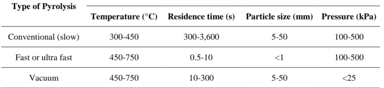
2.2.5 Types of Pyrolysis ... 30
2.2.6 Reactor Technologies ... 32
2.2.8 Nomenclature ... 47
2.2.9 References ... 49
2.3 REVUE CRITIQUE DE LA LITTÉRATURE ... 54
2.3.1 Modèle cinétique ... 54
2.3.2 Bilan d'énergie ... 57
2.3.3 Sélectivité du soufre ... 59
CHAPITRE 3 MODÉLISATION DE LA CINÉTIQUE ... 61
3.1 PRÉSENTATION DE L’ARTICLE ... 61
3.2 PREDICTIVE KINETICS MODEL FOR AN INDUSTRIAL WASTE TIRE PYROLYSIS PROCESS ... 61 3.2.1 Abstract ... 62 3.2.2 Nomenclature ... 62 3.2.3 Intrduction ... 64 3.2.4 EXPERIMENTAL APPARATUS ... 72 3.2.5 PYROLYSIS MODEL ... 74
3.2.6 RESULTS AND DISCUSSION ... 80
3.2.7 CONCLUSIONS ... 93
3.2.8 Acknowledgements ... 94
3.2.9 References ... 94
CHAPITRE 4 MODÉLISATION DU BILAN D’ÉNERGIE ... 97
4.1 PRÉSENTATION DE L’ARTICLE ... 97
4.2 DETERMINATION OF ENTHALPY OF PYROLYSIS FROM DSC AND INDUSTRIAL REACTOR DATA: CASE OF TIRES ... 97
4.2.2 Intrduction ... 98 4.2.3 EXPERIMENTAL APPARATUS ... 112 4.2.4 RESULTS ... 114 4.2.5 DISCUSSION ... 120 4.2.6 CONCLUSIONS ... 129 4.2.7 Acknowledgements ... 131 4.2.8 References ... 131
CHAPITRE 5 LE COMPORTEMENT DU SOUFRE LORS DE LA PYROLYSE DES PNEUS ... 133
5.1 PRÉSENTATION DE L’ARTICLE ... 133
5.2 ON THE BEHAVIOUR OF SULFUR DURING THE PYROLYSIS OF TIRES ... 133
5.2.1 Abstract ... 134
5.2.2 Intrduction ... 134
5.2.3 EXPERIMENTAL APPARATUS ... 145
5.2.4 RESULTS AND DISCUSSION ... 146
5.2.5 CONCLUSIONS ... 169
5.2.6 Acknowledgements ... 170
5.2.7 References ... 170
CHAPITRE 6 DISCUSSION GÉNÉRALE ... 173
CONCLUSION ... 178
LISTE DES TABLEAUX
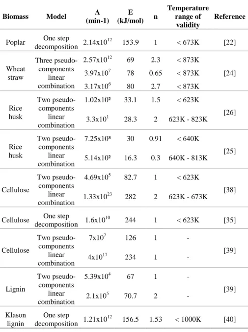
Table 2.2.1 Summary of available biomass feedstock for biorefineries 11 Table 2.2.2 Pyrolysis kinetics parameters for selected materials from literature. 27 Table 2.2.3 Selected feedstocks with their bio-oil main compounds 43 Table 2.3.1 Enthalpies de pyrolyse tirées de la littérature 58 Table 2.3.2 Données de la littérature sur la sélectivité du soufre dans les produits de pyrolyse
60 Table 3.2.1. Types of pyrolysis with their approximate operating parameters. 65 Table 3.2.2. Large-scale pyrolysis processes list. *CFB: Circulating Fluidized-bed, FB: Bubbling Fluidized-bed, RC: Rotating Cone reactor, BRD: Batch Rotary Drum, IRV: Inclined Retort
Vessel 67
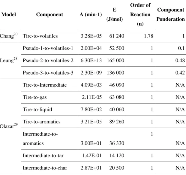
Table 3.2.3. Parameters values for literature models used in this study. 91 Table 4.2.1. Types of reactions involved in pyrolysis and their enthalpic behaviour, as viewed by
the authors. 101
Table 4.2.2. Literature values for heat of pyrolysis for wood and tires. 104 Table 4.2.3. Oxygen distribution among products and pyrolysis yields (Diez et al.). 117 Table 4.2.4. Standard enthalpies of formation calculated for the pyrolysis products at different
operating temperatures. 118
Table 4.2.5. Standard enthalpy change for pyrolysis calculated for different operating
temperatures. 118
Table 4.2.6. Pyrolysis products yields obtained with TGA for samples in DSC cups. 119 Table 4.2.7. Global enthalpy change for pyrolysis at different operating temperatures. 120 Table 4.2.8. Fraction of the global enthalpy change consumed by sensible heat. 129 Table 5.2.1. Literature data on sulfur distribution within the products of waste tire
Table 5.2.2. Data points on sulfur distribution within pyrolysis products from [16] 140 Table 5.2.3. Elemental composition for the inorganics contained in virgin tire resin and char and
oil from an industrial pyrolysis batch (measured via NAA) 147
Table 5.2.4. Elemental composition of the waste tire and char obtained from TGA
pyrolysis. 148
Table 5.2.5. Calculated volatiles elemental composition. 149
Table 5.2.6. Total weight loss and sulfur weight loss during the TGA pyrolysis
experiments. 150
Table 5.2.7. Qualitative observations during and after the TGA pyrolysis experiments. 154 Table 5.2.8. Sulfur distribution (% wt) with steel (Berrueco), without steel (Diez) and simulated
LISTE DES FIGURES
Figure 2.2.1 Geldart classification of particles. 17
Figure 2.2.2 Pyrolysis conceptualizations with a typical thermogravimetric pyrolysis curve. 24
Figure 2.2.3 Pyrolysis units global schemes. 34
Figure 2.3.1 Simulation de la production d’huile/volatiles. 55
Figure 2.3.2 Observation typique d’un pic exothermique dans une courbe DSC lors d’une
experience en pyrolyse. 58
Figure 3.2.1. Simplified representation of the Ecolomondo™ process. 73 Figure 3.2.2. Black box representation of the pyrolysis system. 76 Figure 3.2.3. Product selectivity obtained via isothermal TGA experiments17 (single points) &
calculated selectivity (functions). 81
Figure 3.2.4. TGA data used to identify the oil selectivity curves parameters (5°C/min). 83 Figure 3.2.5. Oil production and temperature (measured & calculated) during an industrial waste
tire pyrolysis batch. 86
Figure 3.2.6. Measured and calculated oil production and temperature for a different heating
profile (batch 1). 89
Figure 3.2.7. Measured and calculated oil production and temperature for a smaller bed
(batch 2) 89
Figure 3.2.8. Calculated volatiles and oil productions with the model from this working
comparison to models by Chang20, Leung28 & Olazar. 92
Figure 4.2.1. Exothermic peak (circled) obtained by Yang et al. during pyrolysis
experiments [3]. 105
Figure 4.2.3. Pyrolysis experiments with natural rubber (NR, left) and styrene-butadiene rubber
(SBR, right) from Yang et al. [3]. 107
Figure 4.2.4. View of the DSC sensor without samples (left) and of the equivalent system of thermal resistances and capacitances with sample (right) [13]. 108 Figure 4.2.5. Typical view of the heat up of a sample with an endothermic transition. 109 Figure 4.2.6. Typical view of a thermal transition measured with a conventional DSC and with
the Tzero (TM) technology [13]. 110
Figure 4,2,7. View of the equivalent steps considered for the global enthalpy change
calculation. 111
Figure 4.2 8. DSC curve (blue) and TGA derivative curve (black) obtained in this work. 114 Figure 4.2.9. Heat capacity for tire and the evolving char as a function of temperature. 116 Figure 4.2.10. Heat flow to the tire shreds simulated with equation (E17). 124
Figure 4.2.11. Heat flows associated with pyrolysis. 126
Figure 4.2.12. Area of the DSC curve corresponding to the exothermic peak. 128 Figure 5.2.1. Sulfur loss selectivities obtained in this work. 152 Figure 5.2.2. Waste tire samples before (tire) and after (char) pyrolysis at 400°C and three
heating rates. 153
Figure 5.2.3. Sulfur loss selectivities for two series of data without steel (original from this work
and from [19]. 157
Figure 5.2.4. ZnO conversion into ZnS through time from [25] 161 Figure 5.2.5. Sulfur loss selectivities: data from this work and data from [18]. 162 Figure 5.2.6. Hydrogen sulfide partial pressure (atm) as a function of time (minutes); Striped line: 400°C, Dotted line: 500°C. Estimated from data obtained [13] and [14]. 164 Figure 5.2.7. Simulated cumulative FeS production during pyrolysis at two temperatures, for 300
LISTE DES SIGLES ET ABRÉVIATIONS
CHAPITRE II
A = Pre-exponential factor [=] s-1 for a 1st order reaction d = Diameter
E = Activation energy [=] Jmol-1 Fr = Froude number
g = Standard gravity [=] m*s-2
h = Heat transfer constant [=] Wm-2K-1 k = Thermal conductivity [=] Wm-1K-1 m = Dimensional & non-dimensional weight n = Order of reaction, non-dimensional Nu = Nusselt number
Pr = Prandtl number
R = Universal gas constant OR Radius [=] Jmol-1K-1 OR m Re = Reynolds number t = Time T = Temperature U = Velocity [=] m*s-1 Symbols µ = Viscosity [=] Pa*s ρ = Density [=] kgm-3 ω = Angular velocity [=] s-1
Subscripts
bed = Fluidized bed
bp = Bed of particles (in rotary drums) g = Gas phase
p = Particle
t = Terminal (velocity)
CHAPITRE III
A Pre-exponential factor (min-1)
CPbed Tire shred bed specific heat (J1kg-1K-1)
CPchar Char heat capacity (J1kg-1K-1)
CPsteel Steel heat capacity (J1kg-1K-1)
CPtire Tire heat capacity (J1kg-1K-1)
Ea Activation energy (J1mol-1)
Fr Froude number
g Gravity constant (m1s-2)
h Average thermal convection coefficient (W1m-2K-1) Hpyr Heat consumed by pyrolysis (J1min-1)
k Kinetics constant (min-1) m Mass (kg)
mbed Mass of bed (kg)
mchar Mass of char (kg)
mpyrolysis Mass of converted pyrolysables (kg)
msteel Mass of steel (kg)
mtire Mass of tire sample (kg)
mtire_initial Mass of initial tire sample (kg)
mvolatiles Mass of generated volatiles (kg)
m∞ Mass of residual solids at 100% conversion (kg)
Mreactant Dimensionless weight
n Order of reaction rchar Reaction rate (min-1)
rdevolatilization Rate of devolatilization (min-1)
rgas Rate of formation of pyrolysis gas (min-1)
ri Rate of formation of pyrolysis product i (min-1)
roil Rate of formation of pyrolysis oil (min-1)
rproducts Rate of formation of pyrolysis products (min-1)
rpyrolysis Rate of pyrolysis (min-1)
rvolatiles Rate of production of volatiles (min-1)
R Perfect gas constant (J1mol-1K-1) Schar Instantaneous char selectivity
Sgas Instantaneous gas selectivity
Si Instantaneous product i selectivity
Soil Instantaneous oil selectivity
t Time (min)
Twall Wall temperature (K or °C)
Tbed Bed temperature (K or °C)
Wexp Tire shred bed surface exposed the drum wall (m2)
Greek letters
ω Rotational speed (s-1)
CHAPITRE IV
c Heat capacity of the pan in DSC
CPbatch Tire batch specific heat (J1kg-1K-1)
CPchar Char heat capacity (J1kg-1K-1)
CPsteel Steel heat capacity (J1kg-1K-1)
CPtire Tire heat capacity (J1kg-1K-1)
C Reference side heat capacitance in DSC
C Sample side heat capacitance in DSC
h Average thermal convection coefficient
H Heat consumed by the charring reactions (J1min-1)
H3charring Constant heat of pyrolysis for the charring reactions (kJ1kg-1) H Heat consumed by the sulfur crosslinks breakage (J1min-1)
H2crosslink Constant heat of pyrolysis for the sulfur crosslinks breakage (kJ1kg-1) H Standard enthalpy of formation (kJ1kg-1)
H Heat consumed by pyrolysis (J1min-1) H1pyrolysis_dmdt Constant heat of pyrolysis (kJ1kg-1)
mactive-sites Mass of active sites for charring (kg)
mbatch Mass of batch (kg)
mchar Mass of char (kg)
mcrosslink Mass of sulfur crosslinks (kg)
mo Initial mass (kg)
mout Mass of material exiting a system (kg) m Mass of pan on reference side in DSC (mg) m Mass of pan and sample combined (mg)
msteel Mass of steel (kg)
mtire Mass of tire sample (kg) q Convection heat flow
Q Heat flow input in a system
q Heat flow through the reference side in DSC
q Heat flow through the sample side in DSC
q Heat flow through the sample in a DSC
q _ Sensible heat flow
R Thermal resistance of pan in DSC
R Thermal resistance of reference side in DSC
R Thermal resistance of sample side in DSC t Time (min)
T Temperature (K or °C) Twall Wall temperature (K or °C)
T Pan and sample temperature in DSC T Reference side pan temperature in DSC T Reference side temperature in DSC
T Sample side temperature in DSC
Wexp Tire shred bed surface exposed the drum wall (m2)
CHAPITRE V
A Pre-exponential factor (min-1) Ea Activation energy (J1mol-1)
k Kinetics constant (min-1) m Mass (kg)
mpyrolysis Mass of converted pyrolysables (kg)
mtire Mass of tire sample (kg)
mtire_initial Mass of initial tire sample (kg) M"# Hydrogen molecular weight
M"#$ Hydrogen sulfide molecular weight
Mreactant Dimensionless weight
m % Initial weight of sulfur n Order of reaction
PH2 Partial pressure of hydrogen
PH2S Partial pressure of hydrogen sulfide r Rate of pyrolysis
rTWL Rate of total weight loss
R Perfect gas constant (J1mol-1K-1) sgas Intrinsic gas selectivity
s"# Intrinsic hydrogen selectivity in non-condensable gas
s"#$ Intrinsic hydrogen sulfide selectivity in non-condensable gas
soil Intrinsic oil selectivity
sSL/TWL Intrinsic sulfur loss selectivity S$)/+,) Global sulfur loss selectivity
s $)/+,) Reference intrinsic sulfur loss selectivity SZnO Surface of active sites available for sulfidation
t Time (min)
T Temperature (K or °C)
INTRODUCTION
Le XXIe siècle est ponctué par des niveaux de surconsommation très élevés. Que ce soit au point de vue alimentaire, matériel, technologique ou autre, le fait est que les sites d’enfouissement des déchets se saturent. Les déchets organiques, outre le constat de leur surconsommation, sont bien assimilés par les sols. Pour une majorité d’autres types de résidus, toutefois, on cherche souvent des moyens de leur donner une nouvelle vie, par exemple en tentant d’exploiter leur potentiel chimique et énergétique.
Le XXe siècle a vu des milliers de projets naître et disparaître, motivés par ces problématiques, espérant en tirer profit, de faire d’une pierre, deux coups. Pourtant, la plupart de ces initiatives n’ont pas eu de succès et sont même souvent mortes dans l’œuf. Les causes sont innombrables : défis techniques et technologiques, problèmes de rentabilité dus à la sous-performance, présence importante d’éléments indésirables dans les résidus et donc, dans les produits, etc. Parfois même le choix de technologie était inapproprié pour l’application visée.
Néanmoins, ces difficultés sont facilement justifiables. Les déchets, peu importe leur provenance ou leur nature, ont certains points en commun : composition, taille et format hétérogènes, présence de contaminants (halogénés, métaux, etc.) importante, faible densité géographique, sont des caractéristiques intrinsèques aux résidus qu’il faut considérer lors de la conception de nouvelles technologies visant à les valoriser.
Parmi les candidats résidus notables, les pneus usagés cadrent très bien avec cette description. Intrinsèquement, les pneus contiennent du soufre et du zinc. Ils sont récoltés entiers et doivent souvent être réduits en charpie pour être récupérés. Dû à leur utilisation sur des véhicules, plusieurs contaminants inorganiques peuvent s’ajouter à cela, suite à leur contact prolongé avec le sol et les routes : alcalins, alcalino-terreux, halogénés et autres. Malgré le fait que certaines
nouvelles technologies permettent de nos jours de retirer la structure d’acier des pneus, il peut être, dans certaines circonstances, souhaitable de ne pas le faire.
Il existe dans le monde des centaines de dépotoirs à pneus usagés, à ciel ouvert, dont plusieurs sont ont été ou sont actuellement la proie d’incendies permanents. De tels événements ont été répertoriés depuis les années 1980, où parfois plus de 10 millions de pneus sont brûlés. Cela a été le cas en 1999, où dans l’état Américain de l’Ohio, un incendie de plus de 25 millions de pneus a causés d’importants dommages environnementaux1. De ces accidents ont émané des quantités importantes d’oxydes de soufre et d’azote, ainsi que des particules fines. Les températures élevées ont favorisé la volatilisation de métaux lourds, tels l’arsenic et le plomb. Les pneus ayant été brûlés avec peu d’oxygène, des goudrons issus de la pyrolyse des pneus ont été libérés dans le sol.
Ces situations demeurent difficiles à éviter principalement à cause de la génération accrue de ces pneus usagés. En effet, il était estimé en 2009 que 5 millions de tonnes de pneus usagés étaient produits aux États-Unis seulement, comme le rapportait la Rubber Manufacturers Association. Environ 15 % de ces pneus se retrouvent dans ces dépotoirs, 12 % des pneus sont enfouis dans le sol, approximativement 30 % sont réutilisés dans des applications commerciales, alors que plus de 40 % des pneus usagés deviennent un carburant dérivé (Tire Derived Fuel, TDF).
Parmi les consommateurs de pneus comme TDF, les cimenteries les alimentent entiers dans des incinérateurs rotatifs, dont les longueurs dépassent parfois les 100 m. Les pneus y sont brûlés à très haute température, générant des niveaux de polluants, tels ceux mentionnés plus haut, au-delà des normes environnementales.
Pour remédier à cette réalité, l’alternative la plus intéressante, pour des applications énergétiques, est la pyrolyse. Le but de cette opération est de produire un combustible plus propre et plus facile à transporter. La pyrolyse des pneus génère essentiellement trois produits : un gaz combustible non-condensable, une huile combustible, possédant des caractéristiques communes avec certaines coupes du raffinage du pétrole, et enfin une poudre de carbone, souvent appelée char. La pyrolyse est une décomposition purement thermique se déroulant en l’absence d’oxygène. Elle se produit à des températures plus basses que l’incinération et la gazéification. Par conséquent, les risques d’évaporation ou de sublimation des métaux, en particulier du zinc, sont grandement réduits.
Puisqu’il n’y a pas d’air présent en pyrolyse, on pourrait la qualifier de prétraitement visant à transformer les pneus afin de purifier et concentrer leur contenu énergétique. Cependant, il a aussi été démontré que la pyrolyse des pneus pouvait, dans certaines situations, produire des quantités significatives de limonène, de toluène, de styrène, de xylène et autres composés chimiques d’intérêt, conférant à la pyrolyse des pneus usagés le potentiel élevé de devenir une application à haute valeur ajoutée.
Toutes ces avenues de valorisation ont captivé l’intérêt des chercheurs et des industriels, qui ont fait de la pyrolyse des pneus un véritable pôle de recherche scientifique et appliquée durant la seconde moitié du XXe siècle.
Dans les premiers temps, les rendements de pyrolyse et la composition chimique des produits pyrolytiques étaient le plus souvent étudiés, en fonction des différents paramètres et facteurs pouvant les influencer. Depuis les années 1990, avec l’avènement des technologies informatiques et la volonté de passer efficacement à l’échelle industrielle, les efforts de recherche ont été dirigés vers la modélisation numérique de la pyrolyse.
La présente recherche doctorale est née dans ces réalités. Un client industriel avait déjà solidement démontré le potentiel de sa technologie de pyrolyse des pneus usagés, conçue dès les
années 1970. Néanmoins, la commercialisation de leur procédé pilote s’est vue ralentie par plusieurs défis techniques. Ce projet doctoral a été lancé dans l’optique de faciliter la progression de son développement commercial.
CHAPITRE 1
PRÉSENTATION DES ÉTAPES DE LA RECHERCHE
Afin d’optimiser l’opération et d’automatiser l’usine, un modèle cinétique de la pyrolyse a été requis. Dès ce premier objectif, il a été possible de détecter de façon généralisée, l’écart notable entre les recherches réalisées en laboratoire et les besoins de cette industrie naissante.
Entre autres constats, la très grande majorité des modèles cinétiques sont développés pour des conditions très peu similaires au contexte industriel. De ce fait, les modèles tirés de la littérature n’ont pas permis de représenter adéquatement l’opération du procédé pilote de pyrolyse des pneus usagés. D’autres recherches dans la littérature ont mis en évidence les mêmes problématiques pour le bilan d’énergie de la pyrolyse et le comportement du soufre.
Pour un procédé énergétique où la connaissance précise de la température est critique, et de surcroît vu la normalisation étroite dont font l’objet les combustibles hydrocarbures pouvant être issus de la pyrolyse quant à leur teneur en soufre, les deuxième et troisième objectifs de ce doctorat sont devenus plus évidents et d’une continuité naturelle avec le premier.
De façon plus globale, le but de ce projet de doctorat a été de produire des outils appliqués pour prédire la production et la qualité de l’huile de pyrolyse des pneus.
En résumé, les objectifs spécifiques de cette thèse sont :
1. Modéliser la cinétique de la pyrolyse des pneus pour un procédé industriel en mode batch, afin de prédire quantitativement et dynamiquement la production de char, d’huile pyrolytique et de gaz non-condensable.
2. Étudier le comportement thermodynamique des pneus en pyrolyse pour caractériser l’évolution de la capacité calorifique et de déterminer l’enthalpie de pyrolyse des pneus, en s’appuyant sur des données de laboratoire et des données industrielles.
3. Investiguer le comportement du soufre lors de la pyrolyse des pneus afin de comprendre et les mécanismes et phénomènes derrière sa migration au sein des trois produits pyrolytiques et de déterminer un état de référence pour la distribution du soufre.
Cette thèse de doctorat est présentée en cinq chapitres, le premier étant celui-ci présentant les étapes de la recherche. Le Chapitre 2 expose une revue de littérature complète ayant été révisée par un comité de pairs ainsi qu’une revue critique de la littérature centrée sur les trois objectifs spécifiques. Le Chapitre 3 présente le modèle cinétique de pyrolyse appliqué à un procédé industriel et concerne donc le premier objectif spécifique. Le Chapitre 4 montre un nouveau bilan d’énergie pour la pyrolyse des pneus et concerne le deuxième objectif spécifique. Le Chapitre 5 discute le comportement du soufre lors de la pyrolyse des pneus et couvre le troisième objectif spécifique.
Le Chapitre 6 contiendra une discussion générale sur les résultats obtenus dans le cadre de ce projet doctoral.
CHAPITRE 2
REVUE DE LA LITTÉRATURE : ACQUISITION D’UNE
BASE DE CONNAISSANCES
Ce chapitre de livre intitulé « Pyrolyis », a été publié dans le livre « Biomass Pre-treatments for Biorefinery Applications » en 2013, aux Éditions Springer, pages 197-227. Cette publication a été révisée par un comité de pairs.
2.1
PRÉSENTATION DE LA PUBLICATION
Puisque cette recherche se fait de concert avec l’étude d’un procédé industriel, une revue de littérature complète est requise. Un livre portant sur les prétraitements de la biomasse pour les bioraffineries nécessitait un chapitre couvrant la pyrolyse. Celui-ci a été révisé par un comité de pairs, comptant donc comme une publication officielle dans le cadre actuel de ce doctorat. Ce chapitre de livre a été structuré de façon à présenter à la fois l’état de la recherche scientifique.
La première section expose les propriétés des différents types de biomasse. La deuxième section montre les familles de modèles cinétiques retrouvés dans la littérature scientifique ainsi que leurs avantages et inconvénients. La troisième section explique les sortes de pyrolyse en fonction de leur vitesse caractéristique. La quatrième section présente des technologies de réacteur sélectionnées pour la pyrolyse de la biomasse ainsi que des exemples de procédés commerciaux en développement. Enfin, la cinquième section discute de points clés à considérer pour l’optimisation des procédés industriels de pyrolyse.
BIOMASS PRE-TREATMENTS FOR BIOREFINERY APPLICATIONS: PYROLYSIS Chapter 11 - Biomass Pre-Treatments for Biorefinery Applications: Pyrolysis
Jean-Remi Lanteigne, Jean-Philippe Laviolette and Jamal Chaouki*
Chemical Engineering Department, École Polytechnique de Montréal, C.P. 6079, succ. Centre-Ville, Montréal, Qc, Canada H3C 3A7
*Corresponding Author ([email protected])
2.2 BIOMASS PRE-TREATMENTS FOR BIOREFINERY APPLICATIONS:
PYROLYSIS
2.2.1 ABSTRACT
Biorefineries are small integrated plants aiming at the recovery of specific biomass wastes via their conversion to high-value biofuels and chemicals. Pyrolysis is among the promising technologies to achieve this goal. Three major factors influence the development of a pyrolysis process: the type of biomass, the process operating conditions and the choice of reactor technology. In this chapter, pyrolysis as a solution to sustain biorefineries is reviewed. The chapter first discusses the various biomass feedstock and their important characteristics. Secondly, the pyrolysis concepts and kinetics are reviewed in light of their importance in process design and modelling. The chapter also discusses the influence of several process conditions and reactor technologies on the pyrolysis reaction and pyrolysis products behaviour. Finally, strategies for product optimization and to avoid purity issues are analyzed. The emphasis of this chapter is put on technologies that have been developed at commercial scale.
Keywords: Biomass, Pyrolysis, Biorefinery, Pre-treatments, Bio-oil, Bio-char, Kinetics, Hydrodynamics.
2.2.2 INTRODUCTION
At the present day, various technologies are presented as feasible to sustain biorefineries [1, 2]. Two main pathways are often highlighted: the thermochemical [3, 4] and the biochemical pathways [5]. Thermochemical pathways involve the decomposition of matter at high temperature in the absence (pyrolysis) or presence (gasification) of oxygen. On the other hand, single and multi-step alcoholic fermentation are the main focus of biochemical process development and involve the digestion of matter by microorganisms.
The development of both thermochemical and biochemical processes face many challenges. Cellulose fermentation processes are characterized by slow reaction rates and low overall yield for non-genetically modified microorganisms [5]. On the other hand, reaching high yield and selectivity remains an issue for both gasification and pyrolysis [4]. However, the thermochemical pathway offers a significant advantage over biochemical processes: reactions rates are high and offer the potential for high product throughput, which is essential to develop a commercially viable industry. Nevertheless, there is an increasing interest in using both pathways in biorefineries such that their respective advantages are exploited.
Gasification is a multi-step process in the context of biorefineries: it yields a synthesis gas rich in hydrogen and carbon monoxide that requires further synthesis to produce “biorefinables” [6]. The second recombination process is performed at mild temperatures with patented catalysts [3, 6] and achieving high conversion as well as high selectivity remains a challenge to this day.
On the other hand, pyrolysis potentially offers interesting techno-economic advantages over gasification since it is a single-step process operating at lower temperature that yields three products: non-condensable gas, condensable gas (oil) and char. [6]. Pyrolysis processes may therefore require significantly less process equipment compared to gasification. Produced from biomass pyrolysis, bio-char have direct applications as activated carbon [7]. Furthermore, bio-oil can be further refined to produce specialty chemicals and/or biofuels in dedicated plants (biorefineries) that this chapter will discuss in more details.
Together with products market value, the operating scale also determines the feasibility of biomass pyrolysis and gasification pathways for biomass pre-treatments for biorefineries. It has been repeatedly demonstrated that gasification is sustainable at very large scale. However, considering that biomass availability is geographically limited, pyrolysis may be better suited for smaller distributed biorefineries. This chapter will discuss biomass pre-treatments for pyrolysis processes as well as pyrolysis as a pre-treatment for further biorefining. The pyrolysis process products and operability depend on several factors including (1) the type of biomass (chemical and physical characteristics), (2) the pyrolysis process operating conditions and (3) the type of reactor (gas/solid hydrodynamics and heat/mass transfer).
2.2.3 TYPES OF BIOMASS
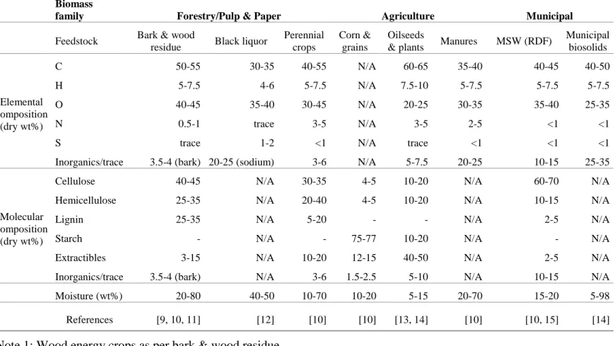
Most of the biomass feedstocks can be classified in three families as defined by the U.S. Department of Energy [8]: Forestry, Agriculture and Municipal. Table 2.2.1 summarizes key chemical and physical characteristics of the main feedstocks that are considered for biorefineries.
Table 2.2.1 Summary of available biomass feedstock for biorefineries
Biomass
family Forestry/Pulp & Paper Agriculture Municipal
Feedstock Bark & wood
residue Black liquor
Perennial crops
Corn & grains
Oilseeds
& plants Manures MSW (RDF)
Municipal biosolids Elemental composition (dry wt%) C 50-55 30-35 40-55 N/A 60-65 35-40 40-45 40-50 H 5-7.5 4-6 5-7.5 N/A 7.5-10 5-7.5 5-7.5 5-7.5 O 40-45 35-40 30-45 N/A 20-25 30-35 35-40 25-35 N 0.5-1 trace 3-5 N/A 3-5 2-5 <1 <1
S trace 1-2 <1 N/A trace <1 <1 <1
Inorganics/trace 3.5-4 (bark) 20-25 (sodium) 3-6 N/A 5-7.5 20-25 10-15 25-35
Molecular composition
(dry wt%)
Cellulose 40-45 N/A 30-35 4-5 10-20 N/A 60-70 N/A
Hemicellulose 25-35 N/A 20-40 4-5 10-20 N/A 10-15 N/A
Lignin 25-35 N/A 5-20 - - N/A 2-5 N/A
Starch - N/A - 75-77 10-20 N/A - N/A
Extractibles 3-15 N/A 10-20 12-15 40-50 N/A 2-5 N/A
Inorganics/trace 3.5-4 (bark) N/A 3-6 1.5-2.5 5-10 N/A 10-15 N/A
Moisture (wt%) 20-80 40-50 10-70 10-20 5-15 20-70 15-20 5-98
References [9, 10, 11] [12] [10] [10] [13, 14] [10] [10, 15] [14]
Note 1: Wood energy crops as per bark & wood residue Note 2: Agricultural crops as per perennial crops
Through the conservation of mass, the biomass chemical composition determines the chemical elements present in the 3 pyrolysis products: non-condensable gas, condensable gas and char. The presence of specific chemical elements in each product fractions is determined by the pyrolysis conditions.
Environmental and purity standards restrict the presence of oxygen, nitrogen, sulphur and inorganics in the pyrolysis products. During pyrolysis, the tendency of producing an aqueous phase generally increases with increasing biomass oxygen fraction (dry weight) since water is produced [16]. The presence of oxygen may also lead to the production of acids, which are detrimental to the oil stability. On the other hand, sulfur and nitrogen are not present in biomass in large amounts as shown in Table 2.2.3, but they will nonetheless be present in the products. In this case, the pyrolysis products may need post-treatment since sulphurous compounds are corrosive, while nitrogen affects reactivity as well as pollutant emissions (fuel-bound NOX, for example). Moreover, these species are also problematic when performing bio-oil upgrade. Finally, inorganics in the biomass and pyrolysis products may represent a risk of slagging and sintering.
Furthermore, the biomass physical properties strongly influence the gas/solid hydrodynamics as well as the heat/mass transfer in the pyrolysis reactor such that it affects the pyrolysis products (respective yield of the three pyrolysis products & their composition). The important physical properties include: the shape of the biomass feedstock, its particle size and moisture fraction. These properties will determine the required biomass physical transformations or pre-treatments.
2.2.3.1 Biomass species
2.2.3.1.1 Bark and wood residues from the pulp and paper sector
Forest mills in the United States of America (USA) produced about 86.7 million dry tons of primary mill residues in 2007 [17], which were composed mainly of bark, sawdust, wood chips and shavings. Of this amount, over 35 million dry tons of wood residues was used as
combustibles and could have been used as a feedstock for biorefineries. Wood pyrolysis has been shown to generate high-value products, such as bio-char (promising activated carbon) and bio-oil. Ensyn and DynaMotive are two companies running commercial-scale pilot plants, which convert wood residue via fast pyrolysis. There are many incentives to develop in situ biorefineries (close to pulp and paper plants) in order to avoid significant issues related to transportation and storage.
2.2.3.1.2 Black liquor
Black liquor pyrolysis has been the subject of several studies, but the main efforts have been invested towards gasification. This has been motivated by the fact that black liquor pyrolysis generates too much solid char [18], which would need to be burned to release the inorganics. The advantage of gasification is that it includes the char combustion process. Thus far, pyrolysis has been mostly considered in the scientific literature as a precursor step to gasification. Consequently, it will not be considered as a potential feedstock for pyrolysis aiming at biorefineries.
2.2.3.1.3 Wood energy crops
The idea of cultivating trees strictly for energy and biorefining purposes has been proposed. Certain fast growing tree species such as cottonwood, aspen and eucalyptus can grow at rates of around 1 m per year or even more. The short-rotation woody crop (SRWC) technique can be used to reach yields of about 10 dry metric tons of woody crops per hectare per year can be achieved. However, the economic viability of SRWC is very fragile due to the high costs of preparation and fertilization of the sites [19].
Depending on the maturity of the woody crops, chemical composition will remain close to that of wood and bark (see section 2.2.2.1.1). The main difference will arise due to the leaves and trimmings, which will accumulate dust and metabolic inorganics up to a few mass percent during the trees’ growth.
2.2.3.1.4 Perennial herbaceous crops
Perennial crops are vegetal not edible for humans, which include among others: switchgrass, weeping lovegrass and Napier grass. Herbaceous crops are usually dedicated to alcoholic fermentation because of their high available complex sugar content, but pyrolysis of these vegetal has been shown to produce high oil yields [20]. The oil produced contained water-soluble and water-insoluble fractions. Moreover, significant amount of alkanes and phenolic compounds can be found in these oils [21] suggesting a high potential of perennial crops for specialty chemicals production from pyrolysis.
2.2.3.1.5 Corn and grains
Alcoholic fermentation has been the main focus for these feedstocks with bioethanol as its main product. With the current problematic surrounding worldwide food supply, it is not ethically and politically justifiable to use food as a fuel while certain countries suffer famine. However, food conservation and storage may sometimes be very difficult and some considerable amounts of corn and grains may become unfit for human consumption. Nevertheless, considering the high starch content and appreciable fermentation yields with this feedstock, it has been rarely studied in fields other than bioconversion.
2.2.3.1.6 Oilseeds and plants
Contrarily to corn and grains, oilseeds and their plants show very poor starch content. Many species, such as colza, are dedicated to the production of biodiesel. Although biodiesel production has been demonstrated technically feasible at large scale, it is not economically sustainable without government grants or incentives. Several studies on oilseeds and plants pyrolysis can be found in the scientific literature, which indicates a strong interest for this conversion technology. As an example, castor bean slow pyrolysis yields easily over 65 % oil with as low as 20 % solid residue [22]. Due to the high oil yield, there is interest in mixing these oils with diesel to produce blends for transportation fuels. However, for the same reasons that
were brought in section 2.2.3.1.5, these feedstocks should not be diverted from their primary function, namely food supply.
2.2.3.1.7 Agricultural crops and residues
The fruits and vegetables harvest and transformation processes yield many wastes: trimmings, hulls and shells. In 1995, the US Department of agriculture estimated that over 250 million dry tons of agricultural crops and residue were generated over a year in the country [23]. The chemical composition of agricultural crops and residues is very similar to that of perennial herbaceous plants (see section 2.2.3.1.4). The interest in these feedstocks is reflected in the abundant literature found on agricultural crops and residues pyrolysis [24, 25, 26].
2.2.3.1.8 Animal manures
Animal manures are used as fertilizers: their high urea, phosphorus and organics content enrich soils dedicated to agriculture. Cattles are the main manure producers with production of over 200 million dry tons a year in the US (commercial broilers are showing comparable numbers) [23]. Because manure has a heterogeneous composition, thermal decomposition has gained interest to recover that feedstock. Cattle manure is more difficult to collect than poultry manure [10]. Therefore, the poultry manure is considered as a good candidate for industrial pyrolysis and the scientific literature has been mostly focused on this type of manure.
2.2.3.1.9 Municipal solid waste (MSW)
Municipal solid waste (MSW) management has become a major issue worldwide. Issues related to landfilling include: occupation of large areas, generation of greenhouse gases by digestion of the waste, generation of hazardous and refuse materials, etc. New recovery strategies to generate energy, such as incineration, have also given rise to many problems. In Europe, particularly in Germany, rotary kiln incinerators has been extensively studied and issues related to the high temperature have been reported: leaching of metals, emission of carcinogen compounds, emission
of particulate matter, etc. Pyrolysis has been identified as a promising avenue for MSW management: its lower operating temperature and absence of oxygen decrease the pollutant emissions as well as the cost of post-treating flue gases.
2.2.3.1.10 Municipal biosolids
Waste water treatment is a critical process for our society: waste water contains dissolved organics and inorganics as well as suspended solids and microorganisms that must be eliminated before the water can be released into the environment or purified further to be drinkable. The recovered waste forms sewage sludge, which is difficult to recycle. When dried, contaminants such as heavy metals limit its potential applications. Currently, it is common practice to incinerate sewage sludge with the similar disadvantages to MSW incineration (see section 2.2.3.1.9). However, incineration could be replaced by more efficient technologies, such as pyrolysis.
2.2.3.2 Feedstock pre-treatment for pyrolysis
Physical pre-treatments are key to control feedstock properties, which significantly influence gas/solid hydrodynamics as well as heat/mass transfer in the pyrolysis reactor. Recommended feedstock pre-treatments depend on the initial biomass characteristics, the pyrolysis conditions as well as the reactor type. Pre-treatments also allow the homogenization of the feedstock characteristics with time.
Intrinsic feedstock properties such as specific heat, thermal conductivity and density (dry and true) cannot be easily modified and constitute limitations for thermal processes. On the other hand, feedstock moisture and particle size are the main physical parameters that can be adjusted to optimize the pyrolysis process performance.
Particle fluidizabiliy has been correlated to its average size and density. Geldart classified particles into four groups (Geldart class A, B, C and D) based on their fluidization behaviour at ambient conditions [27]. Figure 2.2.1 illustrates the Geldart classification of powders and indicates the properties of common feedstocks for biorefineries.
Figure 2.2.1 Geldart classification of particles. Reprinted and modified from ref. [27], Copyright 1973, with permission from Elsevier.
In the Geldart classification, class C (cohesive particles) and D (large particles) can be detrimental to gas/solid mixing as well as heat/mass transfer. For example, these particles cannot be easily and uniformly fluidized in a reactor: class C particles lead to channelling [28]. Furthermore, large particles (class D) are more subject to internal temperature gradients and species diffusion effects, which affect the final pyrolysis product distribution and composition. Species intra-particle diffusion increase the species exposure time to the pyrolysis conditions (additional time for reactions) while temperature gradients lead to uncertainties related to the characterization of the pyrolysis conditions.
Based on typical wood densities (various species) and Figure 2.2.1, sawdust particles (50 500 µm) are classified as Geldart A. On the other hand, coarser bark or wood residue particles are classified as Geldart B or Geldart D.
2.2.3.2.1 Particle size reduction
For particle size reduction, it is preferable to process biomass with low moisture content (after a drying pre-treatment) since its brittleness is increased and higher shear forces are promoted. Taking that into consideration, the most common size reduction techniques are dry shredding and hammermilling. Dry shredding relies on rotating cutters: a geared roll is mounted with sharp designed metal cutters, which are regularly disposed on its surface. Larger wood pieces can this way be converted into wood chips. As smaller pieces will simply bypass the cutters, there is no need to separate the biomass feed before this step. Dry shredding can easily reduce biomass size down to wood chips-like particulate [10].
If a powder-like feedstock (< 500 µm) is required for pyrolysis, further size reduction can be achieved with hammermills [10]. The principle is to grind a material until it reaches a minimal particle size. It is designed to limit particle size by the use of perforated plate outlet whose holes size determines the final average particle diameter. In a small drum, solid metal hammers are mounted on a central shaft. The metal hammers are rotated and the biomass material comes under the action of centrifugal force: the biomass is crushed between the hammers and the drum wall. The drum wall has grooves oriented perpendicular to those of the hammers extremities to maximize shear forces. By gravity, the fine particles percolate at the bottom of the drum where the perforated plate controls their exit in the outlet duct.
2.2.3.2.2 Particle size increase
Some feedstocks are characterized by low densities (such as bark and wood residues) and increasing their particle size may be necessary for some reactor technologies. In fluidized bed reactors, for example, particles with low terminal velocities may be rapidly entrained outside of
the reaction zone resulting only in partial conversion. If the pyrolysis reactor technology requires larger particles, particle agglomeration techniques can be used. Pelletization, also referred to as densification, is a well-established process and it is currently used to transform many MSW into denser particulate RDF (Refuse Derived Fuel) feedstocks to be directly used as fuels [29]. These same processes can also be used for biomass pre-treatment for biorefineries.
The most widely used equipment to produce pellets is the extruder [10]. It consists of one or two (partially overlapped) cylindrical ducts in which screws force deformable solids to flow with very high shear forces. At the end of the extruder, a die controls the pellet average size and a binding agent can be introduced with the solids in order to consolidate the agglomerates. Depending on the objective of the extrusion process, the design can consider multiple outlets to remove water.
Since pulp and paper industry wastes contain significant quantities of water, drying can become very expensive. In this instance, some compacting technologies can mechanically remove water from biomass while forming pellets or briquettes. Some extruders and other hydraulic or pneumatic presses perform compaction as well as remove liquid water. By reaching high pressures using extrusion, Edwards [30] was able to compact a mix of bark and wood residue and lower its moisture content from 56.5 wt% down to 34.8 wt%.
2.2.3.2.3 Drying
Drying constitutes another relevant pre-treatment for bark and wood residues for most pyrolysis reactor technologies. Biomass moisture fraction is generally controlled by the use of rotary drum dryers in the industry [31]. It uses the same principles as conventional clothes dryers: a conditioned air stream with low humidity enters the drum and is charged with moisture evacuated from biomass. Industrial rotary drum dryers can reach volumes as high as 200 m3. Using such drying equipment allows one not only to reach very low moisture fractions, but also attain a given moisture fraction set point that is desired for pyrolysis.
2.2.3.2.4 Sorting
Large pieces of inorganic material (metals and glass, for example) can be present in significant quantities in MSW. Therefore, sorting of MSW is normally required since inert material will not only consume useful volume, while some metal can act as catalyst to produce more pollutants [32].
2.2.3.2.5 Pre-treatment for sewage sludge
In sewage sludge, organic matter is diluted in water and micro-scale inorganic elements can be present. Once the sludge has been chemically and biologically stabilized at the wastewater treatment plant (pH neutralization and microorganisms’ denaturation), dewatering is the first step to recover municipal biosolids. Many techniques can be employed for dewatering and centrifugation is commonly used since it can easily yield suspensions of 20 25 wt% biosolids from 0.5-3 wt% diluted sewage sludge with an overall solids recovery of over 90% [10]. Rotary drum filtration can also be used to remove water at lower levels. Depending on the operation, a controlled flow of air can be injected into the rotary drum filter, which can be used as a dryer to obtain moisture fractions below 10 wt% [10]. The wall of a rotary drum filter is meshed so the gas flow will be radial, as clogging of the filter is avoided by constant scrubbing mechanisms. As pure water can be obtained through the wastewater treatment process, the sludge sequesters impurities, which are then very difficult to remove.
2.2.4 PYROLYSIS REACTION KINETICS
During pyrolysis, the feedstock is decomposed under relatively high temperature (300°C – 1000°C) and anaerobic conditions into three products: char, condensable gas (oil & water) and non-condensable gas.
The non-condensable gas (at ambient temperature) is the lightest pyrolysis product and is composed of small hydrocarbons (C1 C4), carbon dioxide, carbon monoxide, hydrogen and other
trace components. For biomass, the high fraction of molecular oxygen promotes the production of carbon monoxide and carbon dioxide. The fraction of trace components depends on the initial composition of the feedstock: sulfur, nitrogen, phosphorus and inorganics.
The second product is a condensable gas (at ambient temperature) whose composition can significantly vary depending on the process and biomass properties. The condensable gas fraction is characterized by two immiscible phases: an aqueous and an oily phase. Since molecular oxygen is present in biomass, aldehydes, ketones, alcohols and acids are formed during pyrolysis and condense with water to form the aqueous phase. The oily phase regroups all hydrocarbons that are immiscible with water. The remaining esters, phenols, thiols, nitriles, amines, amides can be present in both aqueous and oily phases.
The last product is a solid phase that contains a carbon-rich powder (char or bio-char) and inorganics. For biomass pyrolysis, bio-char can have up to 20 wt% in molecular oxygen. Because of the initial fibrous structure of biomass (particularly in ligneous materials), the bio-char is characterized by a high pore volume and specific surface (after treatment and activation). It thus possesses interesting properties to be used as activated carbon [7].
During the pyrolysis of a specific feedstock, the respective yield and chemical composition of the above three products are governed by the pyrolysis reaction kinetics. Furthermore, the yields and chemical composition can be varied by adjusting the pyrolysis conditions in order to promote certain reactions.
2.2.4.1 Kinetics characterization
Pyrolysis reaction kinetics are characterized by hundreds or thousands of parallel reactions and in series (solid and gas phase). Pyrolysis is governed by several chemical mechanisms: resonance, bond breaking, rearranging, dehydrogenation, cyclization, etc. Due to its complexity, the entire
![Figure 2.2.1 Geldart classification of particles. Reprinted and modified from ref. [27], Copyright 1973, with permission from Elsevier](https://thumb-eu.123doks.com/thumbv2/123doknet/2335628.32615/43.918.214.707.315.683/geldart-classification-particles-reprinted-modified-copyright-permission-elsevier.webp)
![Figure 2.2.3 Pyrolysis units global schemes: a) bubbling fluidized bed [41], b) circulating fluidized bed [41] and c) rotary drum reactor [51]](https://thumb-eu.123doks.com/thumbv2/123doknet/2335628.32615/60.918.215.709.248.640/figure-pyrolysis-schemes-bubbling-fluidized-circulating-fluidized-reactor.webp)