HAL Id: hal-01533215
https://hal-imt.archives-ouvertes.fr/hal-01533215
Submitted on 20 Jun 2017
HAL is a multi-disciplinary open access
archive for the deposit and dissemination of
sci-entific research documents, whether they are
pub-lished or not. The documents may come from
L’archive ouverte pluridisciplinaire HAL, est
destinée au dépôt et à la diffusion de documents
scientifiques de niveau recherche, publiés ou non,
émanant des établissements d’enseignement et de
Ludovic Apvrille, Letitia W. Li
To cite this version:
Ludovic Apvrille, Letitia W. Li. Safe and Secure Support for Public Safety Networks. Daniel Camara,
Navid Nikaein. Wireless Public Safety Networks 3, Elsevier, pp.185 - 210, 2017, 978-1-78548-053-9.
�10.1016/B978-1-78548-053-9.50009-3�. �hal-01533215�
Safe and Secure Support for
Public Safety Networks
Ludovic Apvrille and Letitia W. Li
∗,†System-on-Chip Laboratory (LabSoC) Institut Telecom, Telecom ParisTech
CS 50193, F-06904 Sophia Antipolis cedex, France
SUMMARY
The advent of autonomous vehicles and UAVs offers additional support for disaster relief efforts. These self-managing objects are able to gather data, deploy a wireless network, and other simple routine maintenance tasks, freeing up aid workers to focus their efforts on the rescue itself. Fleets of UAVs may deploy mobile communication networks, and with their mobility advantage, also gather visual images of areas to coordinate relief efforts. Autonomous vehicles may deploy a higher-powered wireless relay, and also transport supplies or evacuate patients from treacherous areas without risking the life of a driver. However, during these precarious situations, faults in the design of these autonomous vehicles, should they be exposed and exploited, may worsen the disaster. It is important to ensure that these deployed autonomous objects will execute both safely and securely. In this chapter, we present a design methodology SysML-Sec in the open-source toolkit TTool for the design and verification of both autonomous objects and mission planning.
key words: Design Space Exploration, Systems-on-Chip, UML, Formal Specification, Model Checking, TTool
1. Introduction
As explained by Tanzi et al. in the first volume of this book [1], communicating and autonomous devices will surely have a play to role in the future Public Safety Networks. The “communicating” feature comes from the fact that the information should be delivered in a fast way to rescuers. The “autonomous” characteristic comes from the fact that rescuers
∗Correspondence to: System-on-Chip Laboratory (LabSoC)
Institut Telecom, Telecom ParisTech, LTCI CNRS
should not have to concern themselves about these objects: they should perform their mission autonomously so as not to delay the intervention of the rescuers, but rather to assist them efficiently and reliably.
Previous work presented how such objects could play a role in PSN, either as an active agent providing a direct support to the network, e.g. as a transmission relay, or as a data provider fed into the network - e.g. a sensor gathering information and relying on the PSN to transmit its data.
In particular, UAVs have already been proposed as a solution to cover both situations. First, they provide a mobile communication network, usually by relying on a fleet of drones. Second, they capture information from e.g. cameras, lidars, and forward these information to the rescuers via the PSN [2]. Contributions in the area have underlined the fact that the drones must be as autonomous as possible for the reasons previously indicated [3].
Other communicating objects can serve as relays: remote sensors, mobile phones, emergency smart watches, smart medical appliances, etc: a PSN will be formed out of a potentially huge set of Internet of Things dedicated to assistance in emergency situations: the Things for PSN (TPSN). TPSNs differ from public Internet of Things because TPSNs are assumed to be highly reliable and secure. Their high level of reliability is due to the fact that rescuers should obtain the right information on time, and the fact that the object itself should not provoke extra damages. The security and privacy constraint is due to the manipulation of highly sensitive information during emergency situations, e.g., the information could be classified as confidential or reserved for justice procedures. Thus, they should not be accessible to journalists or to enemy governmental agencies.
Finally, TPSNs must be safe, secure and autonomous. This chapter focuses on the safety and security aspects, and exemplifies them with an autonomous system. More precisely, we present how these objects could be designed, and how their missions could easily be planned and verified prior to any intervention.
The chapter is organized as follows. In section 2, we present concrete scenarios where autonomous objects could play an interesting role. Section 3 presents the running example. Section 4 presents our modeling and validation method named SysML-Sec. Then, section 5 presents how a mission validation can be modeled and performed with our approach. 6 explains how our approach favourably complements similar contributions. Lastly, section 7 presents the perspective of our approach.
2. Context
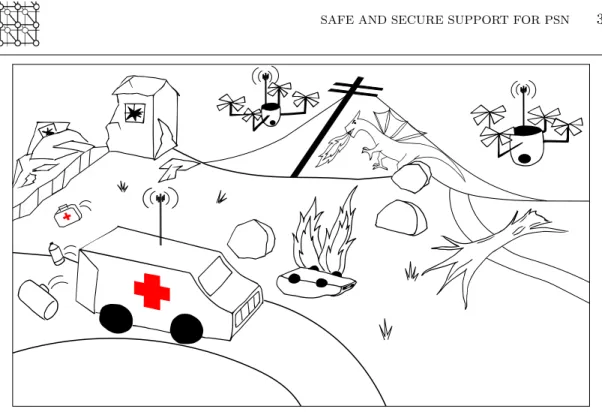
This section presents the roles that autonomous objects could play in the scope of an emergency situation, and how they interact with the PSN deployed in the scope of an emergency situation. We take the example of two different complex and autonomous objects: an autonomous UAV, and an autonomous car. Figure 1 shows a possible scenario using UAVs and an Autonomous Emergency Vehicle during disaster relief.
Figure 1. UAVs and Autonomous Emergency Vehicle support during disaster relief
2.1. UAVs
UAVs could play a key role for the following missions described in [2]. The two first scenarios rely on PSN in order to send their data to the rescuers. In the last scenario, the UAV has a direct role on the PSN.
• Detection and monitoring of people/victims impacted by the crisis. Typically, the drone has to identify groups of disabled persons, and to make a clear distinction between adults and children. Cameras are a good option to find victims. When victims are buried, e.g. when an earthquake occurred, another option is to rely on special antennas to track the electromagnetic fields emitted by personal electronic devices, e.g. smartphones and smartwatches. Indoor navigation could also be used to find victims within building on fire. Last, drones could be used to inform the victims about the situation, e.g. with loud audio messages.
• The continuous assessment of the situation status concerning the impacted area. This task includes the identification of best access roads to the disaster area and to the victims. In this context, “best” may refer to “safe”, or “fast”.
• Offering a mobile relay to the wireless section of the PSN. Contributions in the domain commonly propose using a fleet of drones in order to cover larger wireless communication areas.
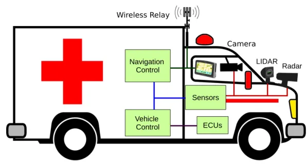
2.2. Autonomous cars Radar Wireless Relay Sensors LIDAR ECUs Vehicle Control Navigation Control Camera
Figure 2. Autonomous Emergency Vehicle
Compared to UAVs, autonomous cars can carry more equipment, have a longer operational time, but are restricted to only slightly damaged areas with traversable roads. Figure 2 shows an Autonomous Emergency Vehicle with sensors and a wireless relay. Their use within an emergency situation includes:
• Carrying material, e.g., bringing water, food or medicines to victims, bringing rescue equipment to rescuers, and bringing energy to other equipments, e.g. reloading spots/charging stations for UAVs. They could also be used to carry victims from dangerous areas without risking the life of a driver.
• Assessing a situation. An autonomous car can easily investigate road quality. It can also deploy its own sensors for data collection.
• Serving as a mobile wireless relay. Emission power can be much higher that of an UAV, but with reduced mobility.
3. Case Study
As own running example, we examine the design of an Autonomous Emergency Vehicle capable of the disaster relief tasks as previously presented. The autonomous vehicle must coordinate with Central Command, receiving command regarding future destinations or operational tasks,
and updated road conditions, while sending gathered data concerning current status of the affected area.
In addition, the Autonomous Emergency Vehicle must navigate to destinations, calculating routes and vehicular operations based on incoming sensor data, such as braking and steering. We present its design in the context of the stages of the SysML-Sec methodology in the following section.
4. Our approach: SysML-Sec 4.1. Methodology
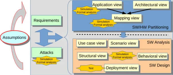
The SysML-Sec methodology, summarized in Figure 3, addresses all stages in the design of an embedded system, with simulation and verification at each stage [4]. We present an overview of all three stages before describing the partitioning stage in detail.
SW/HW Partitioning SW/HW Partitioning Requirements Requirements Architectural view Architectural view Mapping view Mapping view Application view Application view SW Analysis SW Design SW Analysis SW Design Structural view
Structural view Behavioral viewBehavioral view
Deployment view Deployment view Test Attacks Attacks Assumptions Assumptions
Use case view
Use case view Scenario viewScenario view
Simulation Formal analysis Simulation Formal analysis Simulation Formal analysis Simulation Formal analysis
Figure 3. Overall SysML-Sec Methodology
4.2. Analysis Stage
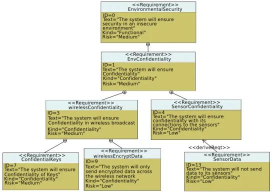
The Requirements/Attacks stage (left section of Figure 3) intends to identify and analyze requirements and attacks together with the main application functions. Requirement graphs help the designer consider the complete system in the first phases of design and serve as a reference for design teams. Figure 4 shows an excerpt of the Environment-related Security Requirements for an autonomous vehicle. Requirements are clarified by being divided into more detailed requirements, until details of their implementation may be described with a <<
deriveReq >> operator. As designers refine the model, they should constantly refer back to the Requirements graphs to ensure they have adhered to the standards.
Figure 4. Extract of Autonomous Vehicle Requirements Diagram
Researchers have recently discovered many vulnerabilities in connected cars. In [5], the authors demonstrated that they could control a vehicle through the Onboard Diagnostic Port (OBD-II) by sending their own generated CAN messages. As many aftermarket devices plug into the OBD-II port and can be managed by smartphone, the compromise of these devices could allow an attacker to remotely control the vehicle. The authors later [6] presented other vulnerabilities, such as a buffer overflow bug which could be exploited so that playing a WMA file would send CAN packets. Most notably, Miller and Valsasek [7] used a vulnerable internet connectivity feature to modify firmware and send forged CAN messages to remotely control the vehicle. This attack required no physical access to the targeted vehicle, as it could attack any vehicle on the Sprint network.
The additional connectivity required of autonomous vehicles provides even more avenues of attack, so the consideration of these attacks is vital to the design process. We capture attack scenarios (which exploit combinations of vulnerabilities) with formally defined attack graphs [8]. Once defined, these graphs can be easily migrated for reuse in analysis of other systems. Attacks can be linked together in order to assess the impact of a specific vulnerability and the need to address it at the risk assessment phase, e.g., once a mapping is under evaluation.
Threats are displayed in blocks representing the target of the attacks, better presenting the attacks in the context of assets. Attacks (<< attack >> stereotype) can be linked together with primitive operators. Those operators are either logical operators like AND, OR, and XOR, or temporal causality operators like SEQUENCE, BEFORE, or AFTER. We consider the temporal constructs describe the attackers operational point of view in embedded systems, in situations where there is a maximum duration between two causally related attacks. For example, when attacking a system with time-limited authentication tokens, the token must be first retrieved, and then the use of this token must occur before its expiration.
Attack instances in different parametric diagrams can be linked together in order to assess the impact of a specific vulnerability and the need to address it at the risk assessment phase. An attack can also be tagged as a root attack, meaning that this attack is at the top of a tree of attacks. Attacks can be linked to requirements, thus allowing an automated check of the coverage of attacks by verifying whether each attack is linked to at least one security requirement.
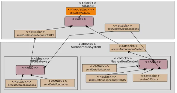
Figure 5 shows a sample attack of recovering GPS data regarding previous destinations, violating user privacy. We predict that the attacker could target either the GPS Gateway or Navigation Control. For example, to succeed in the attack via the GPS Gateway, the attacker must send a command to the GPS to access previous locations, send the data to the attacker, and also interpret or decrypt the received GPS data. The details of individual attacks may be presented in their own attack graphs, such as the steps to gain access to Navigation Control messaging system. As the system is developed, designers may correct vulnerabilities and then indicate certain attacks are impossible. Afterwards, formal verification determines which root attacks are still possible in the system.
4.3. Hardware/Software Partitioning
The Hardware/Software Partitioning stage (upper right of Figure 3) intends to determine what is the best way to implement the embedded system. For example, from a flexibility point of view, software is preferable to hardware. On the contrary, from a power consumption point of view, hardware should be used first. Thus, designing a complex embedded system, such as the embedded system of an autonomous car, requires the use of this methodological stage. Usually, a partitioning follows the Y-chart approach (as shown in the upper right section of Figure 3), first modeling the abstract functional tasks (Application View), candidate architectures (Architectural View), and finally mapping tasks to the hardware components (Mapping View) [9]. Simulation and verification techniques are applied at mapping stage to decide whether the selected architecture complies with the system’s requirement. The HW/SW Partitioning phase of SysML-Sec follows this approach.
4.3.1. Application View
The Application View comprises of a set of communicating tasks. The behavior of tasks is described abstractly. Functional abstraction allows us to ignore the exact calculations and data processing of algorithms, and consider only their relative execution time. Data abstraction allows us to consider only the size of data sent or received, and ignore details such as type, values, or names. On the Component Design Diagram, an extension of the SysML Block Instance Diagram, the designer specifies the list of tasks, and within the task, attributes and ports indicating communication. Purple ports indicate event-based communication and blue ports indicate channel-based communication. Events notify another task about an event, such as the start of a function or a hardware interrupt. Channels are used for the transfer of data. Activity diagrams are used to give a behavior to tasks.
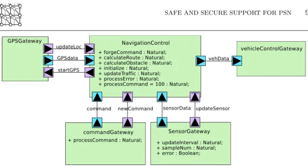
Figure 6 shows the Component Design Diagram of the Autonomous Vehicle in our case study. The design includes a main task “Navigation Control” communicating with “Sensor Gateway” managing all sensor data, “GPS Gateway” managing location data, “Command Gateway” managing commands of new destinations or tasks from Central Command. Based on the input data, Navigation Control calculates a trajectory and sends the driving commands to “Vehicle Control Gateway” which then interfaces with the ECUs.
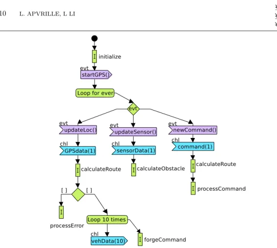
The activity diagram of the Navigation Task is shown in Figure 7. The navigation system starts with an initialization sequence modeled only as an execution time. Next, the Send Event operator signals a start to the GPS Gateway. After the initialization, the navigation task continually waits for any of the 3 possible signals from the other tasks as indicated by the Select Event operator. For example, if it receives the “update Location” event from the GPS, it acquires the new GPS data with the Read Channel operator. Next, it calculates the route based on the new data. If route calculation fails, it processes the error, and if it succeeds, it forges a new command and sends it to the Vehicle Control Gateway by writing data to the “vehData” channel. We model these possibilities with the Choice operator. The loop for ever operator indicates that when one execution branch finishes, execution returns to the start of the loop, and executes the Select Event operator again.
Figure 6. Application View: Component Diagram of Autonomous Vehicle System
4.3.2. Architectural View
The architectural model displays the underlying architecture as a network of abstract execution nodes, communication nodes, and storage nodes. Execution nodes consist of CPUs and Hardware Accelerators, defined by parameters for simulation. All execution nodes must be described by data size, instruction execution time, and clock ratio. CPUs can further be customized with specific parameters e.g.cache-miss percentage, and with information regarding Operating System and middleware properties, e.g., scheduling policy, task switching time, etc. Communication nodes include bridges and buses. Buses connect execution and storage nodes for task communication and data storage or exchange, and bridges connect buses. Buses are characterized by their arbitration policy, data size, clock ratio, etc, and bridges are characterized by data size and clock ratio. Storage nodes are Memories, which are defined by data size and clock ratio.
4.3.3. Mapping View
Mapping partitions the application into software and hardware as well as specifying the location of their implementation on the architectural model. A task mapped onto a processor will be implemented in software, and a task mapped onto a hardware accelerator will be implemented in hardware. The exact physical path of a data/event write may also be specified by mapping channels to buses and bridges, or through associated Communication Patterns [10].
4.4. Software/System Design
Finally, the Software/System Design stage (lower right of Figure 3) develops the functions mapped onto processors at the previous stage. A Partitioning model may be automatically
Figure 7. Application View: Activity Diagram for Autonomous Vehicle Navigation System
translated into the Software/System Design model. Functions to be implemented are first analyzed with SysML-based use case and scenario views to determine a software design. A software design consists of SysML blocks and their interactions, such as operations on data, signal exchange, security protocols. Formal verification intends to prove correct functionality and resilience of the system under design to threats. The functional design is refined until it can be transformed to prototyping code.
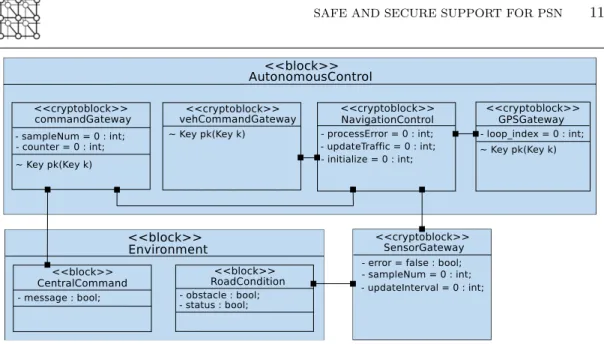
Figure 8 shows the model of the Autonomous System and the environment. As sensor and navigation algorithms are added, the system’s response to various environmental conditions can be simulated and studied.
4.5. Assumptions
Iterations over the complete method are assumption-driven [11]. More precisely, the system specification is first limited in scope, then progressively advanced to include further details. For example, we might first develop the design for functionality of the system, assuming no
Figure 8. Autonomous Vehicle Software/System Design model
attacks are possible. In the next iteration, we remove the assumption on complete lack of attackers and add in security mechanisms, continually evolving the design.
Typical assumptions we could take when designing autonomous cars are “the sensors will never fail” (assumption on the environment), “the power supply of the ECUs will never fail” (assumption on the environment), “the plausibility check function will be ignored” (assumption on the system to be designed). Then, progressively, the system will be refined, and these assumptions will be removed, apart if they are part of the system specification.
4.6. Tooling
All modeling, formal verification, simulation, and code generation is performed within the supporting toolkit TTool. TTool supports the automatic proof from diagrams at the push of a button. Safety proofs can be performed with integrated model-checkers or with UPPAAL [12]. Security proofs are done with ProVerif [13]. For user convenience, results of verifications are also back-traced to the graphical models, without having to investigate the results provided by UPPAAL and ProVerif.
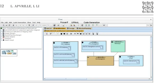
Figure 9 shows a screenshot of TTool. The center shows Diagram Editor displaying the Architecture Diagram of the autonomous vehicle. The left panel shows navigation, search, and analysis tools. The verification and code generation tools are displayed along the top toolbar as labeled.
Figure 9. Screenshot of TTool
4.7. Safety
During partitioning, simulations and formal verification can be used to study safety properties such as schedulability and worst case execution time on a specific architecture. Using execution cycle estimates of algorithms... For example, in the Autonomous Navigation system, we ensure that the max processing time for obstacle detection is ... Once mapping is complete, formal verification confirms reachability of all critical states. Simulations take into account time and show the step by step execution of the application, along with CPU and bus usage. For example, we may wish to determine if each sample of sensor data is processed by the Navigation Unit within a certain time, or ensuring that the vehicle will respond in time to dodge an obstacle. High bus or CPU contention may encourage us to modify the architecture or re-do the mapping, such as providing each Gateway unit with its own CPU.
UPPAAl is a model checker for networks of timed automata. The behavioral model of a system to be verfied is translated into a UPPAAL specification. Safety Proofs conducted with UPPAAL check for unwanted behavior through translation of the model into an automata. For example, UPPAAL may verify the lack of deadlock, such as two threads both waiting for the other to send a message. Behavior may be verified through “Reachability”, “Leads to”, and other general statements. “Leads to” allows us to verify that one state must always be followed by another. For example, in the Autonomous Response Vehicle model, “Abort Mission” by the central command should always be followed by Navigation control executing “Return to base”. The model checker can also verify a statement for all execution flows, A[], or the existence of a single execution flow E<>. For example, it may verify that a state “Route Found” is reachable, with E<> NavigationControl.RouteFound. Critical properties must be preserved at all time, such as the vehicle not continuing to drive when the road is blocked. We might also verify that the Autonomous Vehicle does not send the message when a process error is detected.
4.8. Security
In our context — security in embedded systems —, we focus on the properties of authenticity and confidentiality. These properties are explained in the scope of rescue missions with UAVs and autonomous cars.
Authenticity (or integrity) confirms that a piece of data received by an entity really did originate from the expected sender, and that it was not tampered with. It means that, for a particular exchange, a received message really does correspond to a message sent by the expected entity. In an embedded system, a failure to enforce authenticity may allow an attacker to forge messages, impersonate a trusted component (such as a remote controller), and change the behavior of a system. For example, an attacker forging sensor data may cause an autonomous vehicle’s Navigation Control to calculate trajectory based on the injected data, fail to detect an obstacle, and end up in an accident, resulting in the mission failure, and potentially additional victims. UAVs have already been shown to be vulnerable to GPS spoofing [14].
Confidentiality, in our context, deals with the privacy of sensitive data, such as personal information or credentials. For instance, keys stored in a Trusted Platform Module should probably not be broadcast across an insecure channel. For proposed disaster-relief drones, captured images of victims is sensitive and, for the sake of privacy, they should not be allowed to be intercepted and posted online or published [15]. Also, drones capable of generating a 3D mapping of a building carry a detailed architectural plan of an area, which could be valuable to criminals targeting this location. Even if an attacker physically steals a drone, the on-board sensitive information should remain confidential.
Security analysis is performed with ProVerif, a verification tool operating on designs described in pi-calculus [13]. A ProVerif specification consists of a set of processes communicating on public and private channels. Processes can split to create concurrently executing processes, and replicate to model multiple executions (sessions) of a given protocol. Cryptographic primitives such as symmetric and asymmetric encryption or hash can be modeled through constructor and destructor functions. ProVerif assumes a Dolev-Yao attacker, which is a threat model in which anyone can read or write on any public channel, create new messages or apply known primitives.
ProVerif provides its user with the capabilities to query the confidentiality of a piece of data, the authenticity of an exchange, or the reachability of a state. Traces are generated for all possible execution paths. The tool then presents a result to the user that is either true if the property is verified, false if a trace that falsifies the property has been found, or cannot be proved if ProVerif failed in asserting or refuting the queried property.
4.9. Security Modeling
Security properties can be modeled starting from the Partitioning Phase. On the architectural modeling, buses can be specified as public or private. For example, devices communicating on a WiFi network would be modeled as exchanging over a public bus, while the internal bus would be modeled as private. Private buses are marked secure with a green shield.. The distinctions between bus types also model assumed attacker capabilities: if we assume that an attacker
has no physical access to the system, then we can describe internal buses as private, but if an attacker could physically probe the bus, then it must be indicated as public.
On the application modeling, we use Cryptographic Configurations to model security elements. The configuration types include Symmetric Encryption, Asymmetric Encryption, Hash, Nonce, Key, etc. For each security type, the configuration provides by default estimated values for overhead (additional bits added to the message) and Computational Complexity (additional execution cycles) to help engineers less familiar with security mechanisms. A Cryptographic Configuration can be added as a tag to channels to indicate the data exchanged was first encrypted before transfer. Nonces can be added to messages before encryption.
During the Software/System Design phase, crypto-blocks and encryption/decryption operators are used to model how data is secured. The exchange and subsequent encryption of data is mathematically analyzed to determine if it’s vulnerable to an attacker. For example, the attacker should not be able to forge messages between the command center and autonomous emergency vehicle. Also, we wish to verify the strong authenticity of a message, protecting against replay attacks, that is an attacker recoding a previsouly sent message, and sending it again later on.
5. Mission planning
This section investigates how to formally validate that within a given mission, the system under design — in our case, the autonomous system — will correctly handle its mission in a safe, secure and efficient way.
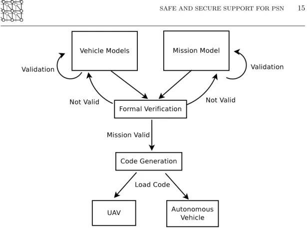
It is unrealistic to test all possible outcomes and execution flows of a mission by hand, and logical flaws or undesired corner cases may not be obvious in a larger model. In particular, the partitioning and design of the system is evaluated with regards to a given environment model, and for a set of standard missions and situations. Thus, for a specific rescue mission, we suggest modeling the mission and then formally verifying it with TTool. Combined with a model of the selected equipment, we can ensure that the mission is possible before sending out the vehicles. We can add “Error states” within the activity diagram, where the state can’t be reached in normal operation, and then use UPPAAL to verify the non-reachability of that state.
The methodology is shown in Figure 10. We start by providing a general behavioral model of the vehicles to be used, which is then refined until it is successfully validated. Then, the specific mission itself is modeled. The formal verifier determines if the mission is feasible under given constraints. If verification of the mission fails, then the engineer must either revise the mission parameters or choose different vehicles to perform the mission, and perform verification again. If the mission is verified possible, then TTool generates code automatically to be loaded aboard the vehicle. For example, we can determine if the UAV is capable of reaching a destination in a given time. We present a simple example with one UAV and one autonomous vehicle.
While it is unnecessary to ensure the mission succeeds in all possible circumstance,s it is necessary to verify that the mission is capable of succeeding. However, it is necessary to ensure that no unsafe situations occur, such as the autonomous vehicle continuing to drive on a road which has been detected damaged. In a mission to deploy a mobile relay, typical mission
Figure 10. Mission Planning Flowchart
verification would involve estimating the feasibility of the solution, taking into account battery life, travel distance, and length of deployment.
Mission planning can involve several vehicles at the same time, and investigate how/when they can collaborate to better fulfill the mission. For example, in the case of a mobile relay, the mission planner can be used to determine how many UAVs shall be used to provide a relay in a given location, taking into account the time to reach the position, the operational time, the time to return, and finally the time to recharge the batteries. It could also be used to model how many backup drones shall be used, and where they should positioned to minimize network failure whenever a current UAV relay fails.
5.1. Mission description
In this example, we propose a mission with 1 UAV, 1 Autonomous Emergency Vehicle, and Central Command which coordinates with both objects. The UAV must scout out a set of locations and send back images, to determine if roads are accessible to the vehicle. Based on road conditions, Central Command directs the Delivery Vehicle to destinations. The Autonomous Emergency Vehicle delivers supplies to directed destinations until none remain, and then returns to base.
The detailed activity diagrams for the actors are shown in Figure 11 and 12. Central Command continually monitors the status of both vehicles, and if inclement weather arises, sends an abort mission message to direct them to return. Using image data sent from the UAV, Central Command automatically processes the data to detect if a destination is reachable or not for the Emergency Vehicle, and sends the Emergency Vehicle the new destination. If no delivery destinations remain, then it directs the Emergency Vehicle to return to base. Red Xs mark states that UPPAAL should verify reachable.
Figure 11. Central Command Activity Diagram
Many vital safety properties must be verified for the mission. For example, the UAV must verify roads to a destination are accessible before the Emergency Vehicle begins to travel. Therefore, there must be no state where the Emergency Vehicle is traveling while the UAV has returned to base. To query this statement in UPPAAL, we write
"E<> UAV.return && AV.travel"
The statement verifies if there exists a state where the UAV is in the return state and the Emergency Vehicle is still traveling.
We also verify correctness in behavior. For example, if Central Command directs to abort the mission, then both the UAV and Emergency Vehicle will return. We express this with a “Leads to” statement,
Figure 12. Autonomous Delivery Vehicle and Unmanned Aerial Vehicle Activity Diagrams
"CentralCommand.abortMission --> UAV.return"
In other words, every time state “abortMission” is reached, it must eventually be followed by the state “return”.
These statements may be entered directly on the UPPAAL model checker, or permanently stored on the model as pragma to be verified in UPPAAL. Their most recent verification status is displayed as a X or a check mark. The pragma is displayed on the block diagram as shown in Figure 13. As shown, UPPAAL has verified that both the UAV and Emergency Vehicle will return after an “abort mission” command. Also, there is never the case where the Emergency Vehicle is traveling while the UAV has returned.
5.2. Integration of Mission Planning and Autonomous Vehicle
In figure 14, we evaluated the partitioning of the AV alone. The figure depicts the mapping view back-traced with the simulation information, e.g. the CPU and bus load. Terminated tasks are depicted in red, and blocked tasks in orange.
We add the mission-specific details to the command module to evaluate the performance impact to determine if the partitioning of the system can still be successfully validated. With the mission loaded, the task Navigation Control must process the new commands, increasing the load on its CPU as shown in Figure 15. Other CPUs and the bus have a lower load because the task “Navigation Control” now creates starvation for other tasks. Thus, a better partitioning would be to increase the CPU frequency, or to discharge this task with hardware accelerators.
Figure 13. Mission Model showing verified Safety Properties
Figure 14. Simulation for System without Mission
6. Related Work
6.1. Embedded System Design
Many toolkits support modeling of embedded systems. They support various stages of the design process.
Figure 15. Simulation for System with Mission
Capella [16] relies on Arcadia, a comprehensive model-based engineering method. It provides architecture diagrams allocating functions to components, allocation of Behavioral Components onto Implementation Components (typically hardware, but not necessarily). Capella provides advanced mechanisms to model bit-precise data structures, and relate them to Functional Exchanges, Component or Function Ports, Interfaces, etc. Capella is however more business focused and supports multiple methodologies.
Design Space Exploration (DSE) of Systems-on-Chip is the process of analyzing various functionally equivalent implementation alternatives to select an optimal solution [17]. The most suitable design is commonly chosen based on metrics such as functionality, performance, cost, power, reliability, and flexibility. At system-level, DSE is challenging because the system design space is extremely large and so usual simulation-based analysis techniques fail to efficiently observe the above mentioned metrics. Contributions on DSE environments such as [18–24] generally rely on a high-level language to describe application functions and architectures. For example, [22–24] rely on UML or MARTE diagrams.
The Architecture Analysis & Design Language (AADL [25]) is a standard from the International Society of Automotive Engineers (SAE). It allows the use of formal methods for safety-critical real-time systems in avionics, automotives, and other domains. Similar to our environment, a processor model can have different underlying implementations and its characteristics can easily be changed at the modeling stage.
6.2. Safety
As safety is important in the management of UAVs and other robotic systems, many previous works have used formal methods to validate mission planning or autonomous systems. [26] used a hybrid partial order forward chaining framework for mission planning. The framework monitors the states of its agents and formally determines allowed new actions based on the current state structure. The system is intended to be used for collaborative Unmanned Aircraft Systems. Similarly, [27] formally validated collective robot systems with KLAIM. Their approach studies robots with a common goal, communicating with each other instead of a central command. Verification analyzes the probabilities of fulfillment of desired formal properties expressed in stochastic logic MoSL. Our approach relies on central command
to communicate with individual autonomous agents and dynamically alter the mission in accordance with environmental conditions. Our verification in UPPAAL relies on states and reachability properties to determine mission success.
Other works validated the architecture and design of the autonomous systems themselves. [28] used Promela/Spin and Gwendolen/AJPF for rule checking Unmanned Aircraft Systems. The UAS must obey “Rules of the Air”, such as detecting collisions and evading them. SPIN/POMELA were used for fast, high-level modeling, and Gwendolen for slower, detailed modeling of interactions. [29] validated the safety architecture of autonomous systems with Event-B. The work intended to verify that the probability of a crash would be less than 10−9 per flight hour, and a single failure did not cause a crash. Our safety verification, however, intends to verify system behaviors and is not concerned with probabilities.
UPPAAL has been used for generally for the formal verification of protocols or designs, such as the Ad Hoc On-Demand Distance Vector routing protocol in [30]. The derived UPPAAL model of the protocol was verified to process all routing messages, and after processing, only optimal routes are found. [31] demonstrated how to use UPPAAL for analysis of timeliness properties of embedded system architectures. However, their automata were manually generated while ours are automatically generated.
6.3. Security
Many projects verify security properties of embedded systems and security protocols. [32] presents a threat model of possible attacks on UAVs to assist designers with risk analysis. Attacks are categorized into Confidentiality, Integrity, or Availability, and then further separated by origin or location of attack.
The Knowledge Acquisition in Automated Specifications approach Security Extension aims to identify security requirements for software systems [33]. The methodology uses a goal-oriented framework and builds a model of the system, and then an anti-model which describes possible attacks on the system. Both models are incrementally developed: threat trees are derived from the anti-model and the system model adds security countermeasures to protect against the attacks described in the anti-model.
The Combined Harm Assessment of Safety and Security for Information Systems (CHASSIS) method considers safety and security together in a common model [34]. Safety and security hazards in the form of misuse cases are developed, and then trade-off analysis to unify all requirements and identify when safety and security conflict. While these techniques targeting the requirements and analysis phase offer a detailed approach to considering threats against safety and security, they are not yet automated.
Other approaches offer comprehensive modeling of security mechanisms intended for the Software/System Design phase. For example, UMLSec [35] is a UML profile for expressing security concepts, such as encryption mechanisms and attack scenarios. It provides a modeling framework to define security properties of software components and of their composition within a UML framework. It also features a rather complete framework addressing various stages of model-driven secure software engineering from the specification of security requirements to tests, including logic-based formal verification regarding the composition of software components.
SecureUML enabled the design and analysis of secure systems by adding mechanisms to model role-based access control [36]. Authorization constraints are expressed in Object Constraint Language (OCL) for formal verification. Our security model focuses on protecting against an external attacker instead of access control. In contrast to formula-based constraints or queries, our approach to security analysis relies on graphically annotating the security properties to query within the model. Our methodology considers security at all stages of the design process, validating partitioning models as well as protocols.
7. Conclusion and perspectives
UAVs and autonomous vehicles may perform routine or dangerous tasks, assisting rescue workers during disaster relief efforts. However, it is important to ensure these autonomous objects are safe and secure, so that they may not be hijacked, leak sensitive data, or further injure victims. We presented how the toolkit TTool can automatically verify missions or autonomous vehicles, requiring no knowledge of the verification languages for a designer.
The main advantage of these UAVs and autonomous vehicles is their ability to free up relief workers to focus on critical tasks. Mission planning and management should require as little manual input as possible. However, mission planning with autonomous objects requires specification of a mission, vehicle characteristics, and communications between central command and all vehicles. Currently, TTool performs validation and code generation automatically, but still requires that a user to manually enter the mission diagrams.
In future work, we consider the addition of new views/diagrams specific to mission planning. Libraries/Patterns modeling common situations/mission requirements will allow for easier and more efficient design of missions. Instead of manually building states and transitions in the diagram, these mission patterns could allow a user to specify only the high-level behavior and automatically receive the low-level implementation details. For example, a user might specify only ”deploy at location X for time Y”, and the UAV would generate their activity diagram, including navigation, battery management, etc.
Furthermore, we will increase the automatic exploration capabilities of TTool, such as automatic selection of vehicles capable of carrying out the current mission. Generic models for common autonomous objects could be provided, allowing the user to customize them with only certain device-specific parameters such as speed, battery life, etc. These mission-focused additions to TTool will better assist relief workers with the automatic planning and management of UAVs and autonomous vehicles, improving the execution and efficiency of rescue efforts during disasters.
Acknowledgment
The authors would like to thank their sponsor, Vedecom, an institute for the development of electric, connected, and autonomous vehicles.
REFERENCES
1. Tanzi T, Isnard J. Wireless Public Safety Networks 1. Overview and Challenges, chap. Public Safety Network: an Overview. ISTE / Elsevier, 2015; 1–20.
2. Tanzi TJ, Apvrille L, Dugelay JL, Roudier Y. Uavs for humanitarian missions: Autonomy and reliability. IEEE Global Humanitarian Technology Conference (GHTC), IEEE: Silicon Valley, USA, 2014.
3. Ranft B, Dugelay JL, Apvrille L. 3d perception for autonomous navigation of a low-cost mav using minimal landmarks. International Micro Air Vehicle Conference and Flight Competition, Toulouse, France, 2013. 4. Roudier Y, Idrees M, Apvrille L. Towards the model-driven engineering of security requirements for embedded systems. Model-Driven Requirements Engineering Workshop (MoDRE), Rio de Janeiro, Brazil, 2013.
5. Koscher K, Czeskis A, Roesner F, Patel S, Kohno T, Checkoway S, McCoy D, Kantor B, Anderson D, Shacham H, et al.. Experimental security analysis of a modern automobile. 2010 IEEE Symposium on Security and Privacy, IEEE, 2010; 447–462.
6. Checkoway S, McCoy D, Kantor B, Anderson D, Shacham H, Savage S, Koscher K, Czeskis A, Roesner F, Kohno T, et al.. Comprehensive experimental analyses of automotive attack surfaces. USENIX Security Symposium, San Francisco, 2011.
7. Miller C, Valasek C. Remote exploitation of an unaltered passenger vehicle. Black Hat USA 2015; . 8. Apvrille L, Roudier Y. SysML-Sec Attack Graphs: Compact Representations for Complex Attacks. The
Second International Workshop on Graphical Models for Security (GraMSec 2015), vol. 9390, Springer, LNCS: Verona, Italy, 2015; 35–49.
9. Kienhuis B, Deprettere E, van der Wolf P, Vissers K. A Methodology to Design Programmable Embedded Systems: The Y-Chart Approach. Embedded Processor Design Challenges, Springer, 2002; 18–37. 10. Enrici A, Apvrille L, Pacalet R. Model-Driven Engineering Languages and Systems: 17th International
Conference, MODELS 2014, Valencia, Spain, September 28 – October 3, 2014. Proceedings, chap. A UML Model-Driven Approach to Efficiently Allocate Complex Communication Schemes. Springer International Publishing: Cham, 2014; 370–385.
11. De Saqui-Sannes P, Apvrille L. Making Modeling Assumptions an Explicit Part of Real-Time Systems Models. 8th European Congress on Embedded Real Time Software and Systems (ERTS2’2016), Toulouse, France, 2016.
12. Bengtsson J, Yi W. Timed automata: Semantics, algorithms and tools. Lecture Notes on Concurrency and Petri Nets, W. Reisig and G. Rozenberg (eds.), LNCS 3098, Springer-Verlag, 2004; 87–124, doi: 10.1007/978-3-540-27755-2.
13. Blanchet B. Automatic Verification of Correspondences for Security Protocols. Journal of Computer Security Jul 2009; 17(4):363–434, doi:10.3233/JCS-2009-0339.
14. Kerns AJ, Shepard DP, Bhatti JA, Humphreys TE. Unmanned aircraft capture and control via gps spoofing. Journal of Field Robotics 2014; 31(4):617–636.
15. Tanzi TJ, Sebastien O, Rizza C. Designing Autonomous Crawling Equipment to Detect Personal Connected Devices and Support Rescue Operations: Technical and Societal Concerns. The Radio Science Bulletin 2015; 355(355):35–44.
16. Polarsys. ARCADIA/CAPELLA (webpage). https://www.polarsys.org/capella/arcadia.html, 2008. 17. Muhammad W, et al.. Abstract application modeling for system design space exploration. Euromicro
Conference on Digital System Design (DSD’06), Dubrovnik, Croatia, 2006.
18. Balarin F, et al.. Hardware-Software Co-Design of Embedded Systems, The POLIS Approach. 5 edn., KLUWER ACADEMIC PUBLISHERS, 2003.
19. Wolf PVD, et al.. A methodology for architecture exploration of heterogeneous signal processing systems. 1999 IEEE Workshop on Signal Processing Systems (SiPS99), 1999.
20. Chatelain A, et al.. High-level architectural co-simulation using Esterel and C. Proc. of IEEE/ACM symposium on Hardware/software codesign, 2001.
21. Assayad I, Yovine S. A framework for modelling and performance analysis of multiprocessor embedded systems: Models and benefits. Proceedings of the 8th conference on Nouvelles Technologies de la Distribution (NOTERE’2007), Marrakech, Marocco, 2007.
22. Schattkowsky T, et al.. A model-based approach for executable specifications on recon figurable hardware. Design, Automation and Test in Europe Conference and Exhibition, 2005. DATE’05, 2005; 692–697. 23. Kukkala P, et al.. Performance Modeling and Reporting for the UML 2.0 Design of Embedded Systems.
Proc. of the 2005 International Symposium on System-on-Chip, 2005; 50–53.
24. Vidal J, de Lamotte F, Gogniat G, Soulard P, Diguet JP. A co-design approach for embedded system modeling and code generation with uml and marte. Design, Automation and Test in Europe Conference
and Exhibition, 2009. DATE’09, 2009; 226–231.
25. Feiler PH, Lewis BA, Vestal S, Colbert E. An overview of the SAE architecture analysis & design language (AADL) standard: A basis for model-based architecture-driven embedded systems engineering. IFIP-WADL, IFIP, vol. 176, Dissaux P, Filali-Amine M, Michel P, Vernadat F (eds.), Springer, 2004; 3–15. 26. Kvarnstrm J, Doherty P. Automated planning for collaborative uav systems. Control Automation
Robotics Vision (ICARCV), 2010 11th International Conference on, 2010; 1078–1085, doi: 10.1109/ICARCV.2010.5707969.
27. Gjondrekaj E, Loreti M, Pugliese R, Tiezzi F, Pinciroli C, Brambilla M, Birattari M, Dorigo M. Towards a Formal Verification Methodology for Collective Robotic Systems. Springer Berlin Heidelberg: Berlin, Heidelberg, 2012; 54–70.
28. Webster M, Fisher M, Cameron N, Jump M. Formal Methods for the Certification of Autonomous Unmanned Aircraft Systems. Springer Berlin Heidelberg: Berlin, Heidelberg, 2011; 228–242.
29. Chaudemar JC, Bensana E, Seguin C. Model based safety analysis for an unmanned aerial system. DRHE 2010 - Dependable Robots in Human Environments, Toulouse, France, 2010. URL http://oatao.univ-toulouse.fr/4153/.
30. Fehnker A, van Glabbeek R, H¨ofner P, McIver A, Portmann M, Tan WL. Automated Analysis of AODV Using UPPAAL. Springer Berlin Heidelberg: Berlin, Heidelberg, 2012; 173–187.
31. Hendriks M, Verhoef M. Timed automata based analysis of embedded system architectures. Proceedings 20th IEEE International Parallel Distributed Processing Symposium, 2006; 8 pp.–, doi: 10.1109/IPDPS.2006.1639422.
32. Javaid AY, Sun W, Devabhaktuni VK, Alam M. Cyber security threat analysis and modeling of an unmanned aerial vehicle system. Homeland Security (HST), 2012 IEEE Conference on Technologies for, 2012; 585–590, doi:10.1109/THS.2012.6459914.
33. van Lamsweerde A. Elaborating Security Requirements by Construction of Intentional Anti-Models. In Proc. of the 26th International Conference on Software Engineering , ICSE ’04 2004; :148–157. 34. Raspotnig C, Katta V, Karpati P, Opdahl AL. Enhancing CHASSIS: A Method for Combining Safety and
Security. Availability, Reliability and Security (ARES), 2013 Eighth International Conference on, 2013; 766–773, doi:10.1109/ARES.2013.102.
35. J¨urjens J. UMLsec: Extending UML for Secure Systems Development. Proceedings of the 5th International Conference on The Unified Modeling Language, UML ’02, Springer-Verlag: London, UK, UK, 2002; 412– 425. URL http://dl.acm.org/citation.cfm?id=647246.719625.
36. Lodderstedt T, Basin D, Doser J. SecureUML: A UML-based Modeling Language for Model Driven Security. 5th International Conference on the Unified Modeling Language 2002; :426–441.