HAL Id: hal-00959842
https://hal.archives-ouvertes.fr/hal-00959842
Submitted on 17 Mar 2014
HAL is a multi-disciplinary open access
archive for the deposit and dissemination of
sci-entific research documents, whether they are
pub-lished or not. The documents may come from
teaching and research institutions in France or
abroad, or from public or private research centers.
L’archive ouverte pluridisciplinaire HAL, est
destinée au dépôt et à la diffusion de documents
scientifiques de niveau recherche, publiés ou non,
émanant des établissements d’enseignement et de
recherche français ou étrangers, des laboratoires
publics ou privés.
Nonsingular change of assembly mode without any cusp
Michel Coste, Damien Chablat, Philippe Wenger
To cite this version:
Michel Coste, Damien Chablat, Philippe Wenger. Nonsingular change of assembly mode without any
cusp. Jadran Lenarcic; Oussama Khatib. Advances in Robot Kinematics, Springer, pp.105-112, 2014,
978-3-319-06697-4. �10.1007/978-3-319-06698-1_12�. �hal-00959842�
any cusp
Michel Coste, Damien Chablat and Philippe Wenger
Abstract This paper shows for the first time a parallel manipulator that can execute nonsingular changes of assembly modes while its joint space is free of cusp points and cuspidal edges. The manipulator at hand has two degrees of freedom and is derived from a 3-RPR manipulator; the shape of its joint space is a thickening of a figure-eight curve. A few explanations concerning the relationship between cusps and alpha curves are given.
Key words: parallel robots, singularities.
1 Introduction
The nonsingular change of assembly mode in parallel manipulators was first ob-served by C. Innocenti and V. Parenti-Castelli [1]. The possibility to execute such a motion is most frequently associated with the presence of cusps, and the non-singular change of assembly mode is realized by turning around a cusp point, or a cuspidal edge of the singularity surface (see for instance [2, 3, 4, 5]). It has also been reported [6, 7] that nonsingular change of assembly modes can be realized by following an “alpha curve” (i.e. a fold curve intersecting itself transversally) but, in the examples shown, such an alpha curve is always associated with the presence of cusps. Figure 1 shows such an example. The figure depicts a slice of the joint space for a 3-RPR manipulator, along with a nonsingular assembly mode changing trajec-tory that goes around the alpha-curve. The zone with four (resp. two) solutions to
Michel Coste
IRMAR, Universit´e de Rennes 1 – CNRS, e-mail: [email protected] Damien Chablat
IRCCyN, CNRS – ´Ecole Centrale de Nantes, e-mail: [email protected] Philippe Wenger
IRCCyN, CNRS – ´Ecole Centrale de Nantes, e-mail: [email protected]
2 Michel Coste, Damien Chablat and Philippe Wenger
the direct kinematic problem is colored in green (resp. red). Going from the green zone to the green zone following the trajectory, one passes from one solution to the other solution in the same aspect. Since there are two cusps, note that a nonsingular change of assembly mode may also be executed by encircling one of them.
Fig. 1 Change of assembly mode looping around an alpha curve, with a zoom on the zone with four solutions to the direct kinematic problem
In the present paper we describe a planar parallel manipulator with two degrees of freedom which has absolutely no cusp, but nevertheless allows nonsingular changes of assembly modes. This manipulator is derived from a 3-RPR manipulator with one prismatic articulation blocked, coupled with a mechanism for reversing an an-gle. We describe this manipulator in the next section. The idea behind the special design of this manipulator is to obtain a joint space which has the shape of a thick-ened figure-eight curve. This is first established with an asymptotic simplification of the inverse kinematic mapping in section 3. Section 4 contains the actual example of a nonsingular change of assembly mode showing no cusp at all. Some remarks on stable singularities are given in section 5; in particular, we comment about the relationship between cusps and alpha curves.
2 The non cuspidal manipulator
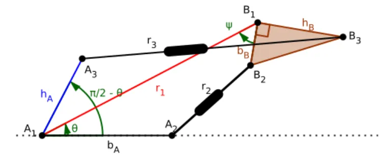
The manipulator we describe here derives from a planar 3-RPR. It has a triangular moving platform B1B2B3which is linked to the base A1A2A3via three legs AiBi, with passive rotoidal joints at Aiand Bi(for i= 1,2,3). The length r1of the leg A1B1is fixed. The lengths r2and r3of the other two legs A2B2and A3B3are controlled by actuated prismatic joints. The vertices A1and A2of the base are fixed. The length A1A3is fixed. The peculiarity of this manipulator, which makes it different from a 3-RPR with one blocked prismatic joint, is the fact that the angle \A2A1A3 varies.
Precisely, if we denote byθ the angle \A2A1B1, then \A2A1A3=
π
2 −θ (see Figure 2).
Fig. 2 The manipulator
Let us complete the description of the manipulator. The platform B1B2B3 is a right-angled triangle, with right angle at B1. Its dimensions are given by bB= B1B2 and hB= B1B3. The dimensions of the base are given by bA= A1A2and hA= A1A3. The position of the manipulator is completely described by the anglesθ andψ=
\
B2B1A1.
We explain now how one can constrain the angle \A2A1A3to be equal to
π
2 −θ. Consider a 4-bar kite A1CDEwith A1C= A1Eand CD= ED. The rotoidal joint A1 is fixed and D is constrained to glide on A1A2. The rotoidal joint E is on the leg A1B1. Of course, we have \A2A1C= −θ. We constrain A1A3to be orthogonal to A1C so that \A2A1A3=
π
2−θ(see Figure 3, left).
Fig. 3 The 4-bar kite and the two coupled kites
When the 4-bar kite is flat (this happens when θ = 0 orπ), it can change its operating mode by moving in such a way that C and E remain coincident. In order to rule out this possibility, we can couple the first kite A1CDE with a second one A1C
′
4 Michel Coste, Damien Chablat and Philippe Wenger
We could have used other mechanisms in order to reverse the angleθ: for in-stance Kempe’s reverser consisting of two contra-parallelograms (see [8] p.270), or belts, or gears.
3 The inverse kinematic mapping and its asymptotic
simplification
The constraint equations of the manipulator can be written as follows. Recall that
riis the length of the leg AiBi. The actuated joint variables are r2and r3, while r1 is fixed. The position of the manipulator is determined by the anglesθ andψ. We have:
r22= (r1−bAcosθ−bBcosψ)2+ (bAsinθ+ bBsinψ)2,
r23= (r1−hAsin 2θ−hBsinψ)2+ (hAcos 2θ+ hBcosψ)2.
(1)
Equations (1) describe the inverse kinematic mapping from the workspace, which is a torus parametrized by the anglesθandψ, to the actuated joint space, which is the positive quadrant parametrized by the lengths r2and r3.
We shall now consider the asymptotic version of the inverse kinematic mapping as r1tends to infinity, as was done in [9] for the usual 3-RPR manipulator. In order to do this, we replace r2and r3 with r2−r1and r3−r2 and take their limitδi= limr1→∞(ri−r1) for i = 2,3. We obtain:
δ2= −bAcosθ−bBcosψ,
δ3= −hAsin 2θ−hBsinψ.
(2)
Equations (2) describe the asymptotic simplification of the inverse kinematic map-ping, from the torus(θ,ψ) to the plane (δ2,δ3). The singularities of the asymptotic inverse kinematic mapping are easily understood. Remark that(bAcosθ,hAsin 2θ) is a parametrization of a figure-eight curve, or lemniscate of Gerono (a particular case of a Lissajous curve), while(bBcosψ,hBsinψ) is, of course, the parametriza-tion of an ellipse. So the curve of critical values of the asymptotic inverse kinematic mapping is the envelope of a family of translated ellipses with centres on a figure-eight curve. If the ellipse is small compared to the figure-figure-eight curve, we obtain just a thickening of the figure-eight curve.
Specifically, take bA= 10, hA= 5, bB= 1, hB= 2. The Jacobian determinant of the asymptotic inverse kinematic mapping is then
J= −20 sinθcosψ+ 10 cos 2θsinψ. (3) Solving J= 0 for ψ, we obtain that the critical points of the asymptotic inverse kinematic mapping are those such that
cosψ=p±cos 2θ
1+ 4 sin4θ , sinψ=
±2 sinθ p
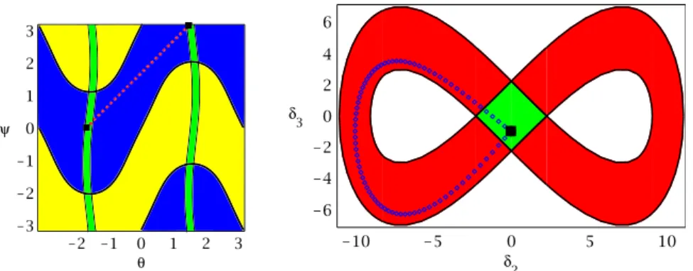
The two branches of the curve of critical points in the(θ,ψ) torus are represented in thick black line in Figure 4, left. These two branches delimit two aspects.
Carrying these values in the equations (2) for the asymptotic inverse kinematic mapping, we get the two branches of the curve of critical values in the(δ2,δ3) plane. They are represented in Figure 4, right. These curves delimit zones where the direct kinematic problem has two solutions (red zone), and four solutions (green zone).
Fig. 4 Work space: the(θ,ψ) torus (left) and joint space: the (δ2,δ3) plane (right) for the
asymp-totic model
There is no cusp, but a nonsingular change of assembly mode is possible since there are two aspects and a zone where the direct kinematic problem has four solu-tions. A trajectory for such a nonsingular change of assembly mode is represented in Figure 4. The nonsingular change of assembly mode can be interpreted using a comparison with a figure-eight race track where the crossroads is realized with a bridge, i.e. there are two levels at the crossroads. Each level is associated with an assembly mode. The track represents an aspect (the joint space is made of two su-perimposed similar aspects). Starting from the crossroads on the bridge (level 1), the car can drive until it reaches the crossroads at the same horizontal position but under the bridge (level 0).
The characteristic curves have been plotted in thin black line in Figure 4, left. These curves, together with the critical curves, define the uniqueness domains: any two points in the same uniqueness domain of the(θ,ψ) torus have different images in the (δ1,δ2) plane (joint space). For a complete definition of the characteristic surfaces and uniqueness domains, see [10]. Any point in the green region of the joint space (Figure 4, right) is the image of four points in the workspace (four assembly modes). These four points are distributed in the four green regions shown in the workspace (Figure 4, left), two in each aspect.
The preceding analysis concerns, of course, only an asymptotic case. However, since the asymptotic inverse kinematic mapping has only stable singularities (folds and transverse intersection of folds, see Section 5) which are not altered by small perturbations, the conclusion obtained will remain valid for all sufficiently large values of r1. We shall check this in the next section.
6 Michel Coste, Damien Chablat and Philippe Wenger
4 An actual, non asymptotic example
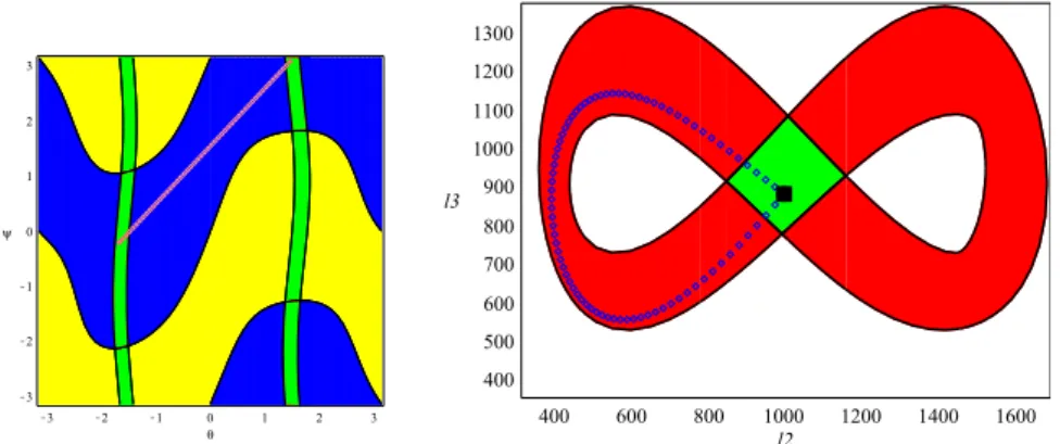
The asymptotic analysis of the preceding section corresponds to r1= ∞. We show here that the conclusion remains valid for r1= 30 (keeping the same bA,hA,bB,hB). We have now to deal with equations (1) which are more complicated than their asymptotic simplification. The computation is done using the SIROPA library. In order to simplify calculations, we use coordinates l2= r22, l3= r
2
3for the actuated joint space, which is an unessential change.
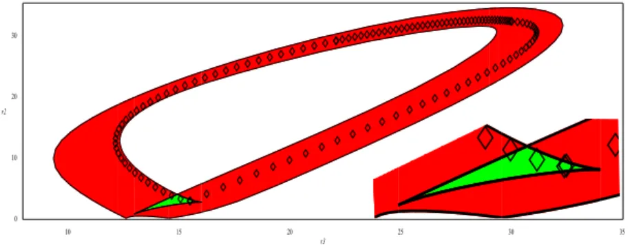
Fig. 5 Workspace and joint space for r1= 30, with a nonsingular change of assembly mode
We can see on Figure 5 that the picture of the singularities is the same as the one for the asymptotic simplification (Figure 4). In particular, there is no cusp. We have also represented a nonsingular trajectory between two configurations corresponding to the same values l2= 1000, l3= 880 for the actuated joints.
5 Stable singularities and nonsingular change of assembly modes
The only stable singularities of a mapping from a surface to a surface (see [11]) are the folds (codimension one singularity, giving a fold curve), the cusps and the transverse intersections of fold curves (codimension two singularities, i.e. isolated points). Any other singularity will be decomposed into a combination of these stable singularities by a small perturbation, whereas a stable singularity is persistent under small perturbations.
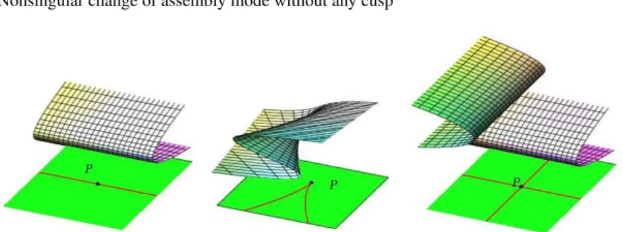
Figure 6 represents these three stable singularities for a critical value P. Gener-ically, the picture of parallel singularities in a two-dimensional surface around a critical value of the inverse kinematic mapping in the joint space will fit into one of these three cases. The direct kinematic problem has a double solution for a fold, a triple solution for a cusp and two double solutions for a transverse intersection of fold curves.
Fig. 6 Stable singularities: fold, cusp and transverse intersection of fold curves
The only stable singularity which allows local nonsingular change of assembly mode is the cusp. By “local”, we mean that the change of assembly mode is per-formed by following a loop which can be shrunk to become arbitrarily small. This is certainly the case for a loop encircling a cusp, but not for a loop following an “alpha curve”, i.e. a fold curve intersecting itself transversally.
In examples, an alpha curve is frequently associated with cusps because a transversal intersection of folds often appears after a “swallowtail bifurcation” (see [12] p. 34), together with a pair of cusps. One might think that a cusp is obtained by shrinking the loop of an alpha curve to a point. This is not the case, since a cusp is a stable singularity which cannot be obtained by degenerating another singularity. If the loop of an alpha curve is shrunk to a point, then this point corresponds to a quadruple, not triple, solution to the direct kinematic problem.
In order to illustrate an example of degeneration of an alpha curve, and also the swallowtail bifurcation, we show the transformation of the(δ2,δ3) joint space of section 3, as we decrease hAkeeping the other dimensions fixed. Only a half of the joint space is shown in Figure 7, since it is symmetric.
Fig. 7 Degeneration of an alpha curve
Figure 7 shows that, at first, two cusps and a transverse intersection of fold curves appear as a result of a swallowtail bifurcation. Then, the two transverse intersections of fold curves disappear through a tangent crossing of these curves.
8 Michel Coste, Damien Chablat and Philippe Wenger
6 Conclusion
While it is clear that the existence of cusps or cuspidal edges is a sufficient condi-tion for allowing a nonsingular change of assembly mode, the quescondi-tion of whether this condition is necessary or not remained to be fixed because previous examples of nonsingular assembly mode changing manipulators always exhibited cusps, even in the presence of an alpha-curve. This paper showed that the aforementioned con-dition is indeed not necessary, through the presentation of a 2-DOF parallel manip-ulator that can execute a nonsingular change of assembly mode while its joint space is free of cusps. This manipulator is derived from a 3-RPR and its joint space is a thickening of a figure-eight curve. The kinematic properties of this manipulator were first established using the asymptotic simplification of its inverse kinematic mapping.
It was recalled that a cusp is a necessary and sufficient condition for local non-singular change of assembly mode in generic situations; it was also explained that a cusp cannot be interpreted as a degeneration of an alpha-curve.
References
1. C. Innocenti and V. Parenti-Castelli, “Singularity-free evolution from one configuration to another in serial and fully-parallel manipulators?, J. Mech. Des., 120: 73-79 (1998)
2. P.R. McAree and R.W. Daniel, “An explanation of never-special assembly changing motions for 3-3 parallel manipulators”, The International Journal of Robotics Research, 18(6): 556-574 (1999)
3. M. Zein, P. Wenger and D. Chablat, “Singular curves in the joint space and cusp points of 3-RPR parallel manipulators”, Robotica, 25(6): 717-724 (2007)
4. S. Caro, P. Wenger and D. Chablat, “Non-singular assembly mode changing trajectories of a 6-DOF parallel robot”. In: Proceedings of the ASME 2012 International Design Engineering
Technical Conferences & Computers and Information in Engineering Conference IDETC/CIE 2012, pp 1245-1254, 2012.
5. M. Husty, J. Schadlbauer, S. Caro and P. Wenger, “The 3-RPS manipulator can have non-singular assembly-mode changes”. In: Computational Kinematics, Mechanisms and Machine
ScienceVol. 15, pp 339-348. Springer (2014)
6. H. Bamberger, A. Wolf and M. Shoham, “Assembly mode changing in parallel mechanisms”,
IEEE Transactions on Robotics, 24(4): 765-772 (2008)
7. E. Macho, O. Altuzarra, C. Pinto and A. Hernandez, “Transitions between multiple solutions of the direct kinematic problem”. In: Advances in Robot Kinematics: Analysis and Design, pp 301-310. Springer (2008)
8. G. Koenigs, Lec¸ons de cin´ematique. Hermann (1897)
9. M. Coste, “Asymptotic singularities of planar parallel 3-RPR manipulators”. In: Latest
Ad-vances in Robot Kinematics, pp 35-42. Springer (2012)
10. P. Wenger and D. Chablat, “Uniqueness domains in the workspace of parallel manipulators”. In: I.F.A.C-Symposium on Robot Control (SYROCO’97), pp 431-436 (1997)
11. H. Whitney, “On singularities of mappings of Euclidean spaces, I. Mapping of the plane into the plane” Annals of Mathematics 62(3): 374-410 (1955)