Faculté de génie
Département de génie civil
B
EHAVIOR OF
S
LENDER
C
ONCRETE
C
OLUMNS
R
EINFORCED WITH
GFRP-B
ARS AND
S
PIRALS
UNDER
C
ONCENTRIC AND
E
CCENTRIC
L
OADS
É
TUDE DU COMPORTEMENT DE COLONNES ÉLANCÉES EN BÉTON ARMÉ DE BARRESET DE SPIRALES DE
PRFV
SOUS CHARGES AXIALES ET EXCENTRIQUESThèse de doctorat
Spécialité : génie civil
W
ASEEM
M
OHAMMED
A
BDELRAHMAN
A
BDELAZIM
(W
ASEEM
A
BDELAZIM
)
A dissertation submitted in partial fulfilment of the requirements for the degree of
Doctor of Philosophy (Civil Engineering)
Sherbrooke (Québec) Canada March 2020
MEMBRES DU JURY
Prof. Brahim Benmokrane Directeur
Prof. Adel ElSafty Évaluateur
Prof. Emmanuel Ferrier Évaluateur
Prof. Sebastien Langlois Évaluateur
Prof. Nathalie Roy Rapporteur
i
A
BSTRACT
apid innovations in the concrete industry and high-strength materials have allowed for the design of more slender members more than the past, such as slender reinforced concrete (RC) columns. Such members suffer several corrosion problems if traditional steel is used as an internal reinforcement material. Consequently, reinforcing slender RC columns with the non-corrosive fiber-reinforced polymers (FRP) reinforcement extends the structure’s lifetime span and can eliminate the high repair and rehabilitation expenditures due to the inevitable corrosion of conventional steel. This undoubtedly satisfies the designers’ needs and successfully introduces FRP-reinforcements in the construction market. However, limited endeavors have been driven to investigate the structural performance of slender RC columns entirely reinforced with FRP-bars. Moreover, current design recommendations proposed for slender FRP-RC columns have many discrepancies attributed to the slenderness limit and the effective flexural stiffness.
The research program herein has been directed to experimentally and theoretically assess the structural behavior of GFRP-RC columns. Therefore, thirty-four GFRP-RC columns with various slenderness ratios were prepared and tested at four different initially applied eccentricity ratios (0, 16 %, 33 %, and 66 %). In addition, four steel-RC slender columns were conducted and observed at the same conditions of GFRP-RC ones to serve as benchmarks. Besides the reinforcement type, the slenderness, and the eccentricity ratios, test variables were also included the longitudinal and transverse reinforcement ratios and the concrete compressive strength. Based on the test results, the GFRP longitudinal-bar contribution to the column capacity and its provision of adequate stability can be described as “significant” over the wide range of parameters tested. Then, the research was extended, developing a second-order model for slender FRP-reinforced concrete columns accounted for materials and geometrical nonlinearities. A good correlation was observed between the generated analytical model and the experimental results of the current study and more than 120 FRP-RC columns were assembled from the literature. The developed model was therefore employed to provide design provisions for slenderness lower and upper limits and to refine the moment magnifier approach
addressed in North American codes and guidelines to accommodate GFRP-RC columns. This included proposing simple and practical design equations for the effective flexural stiffness of GFRP-RC columns based on a multiple linear regression analysis of more than 9,500 slender GFRP-RC columns.
Finally, the experimental and analytical evidence from this study provide valuable data and design provisions that encourage implementation of GFRP reinforcement in slender RC compression members. These provisions, therefore, support including sections dealing with the design and use of non-prestressed slender compression members (columns, piles, and piers) entirely reinforced with GFRP bars into the future editions of the AASHTO LRFD Bridge Design Guide Specifications for GFRP-Reinforced Concrete (AASHTO 2018a), CAN/CSA S6-19 (CSA 2019), ACI 440.1R-15 (ACI 2015), and CSA S806-12 (CSA 2012).
Keywords: Concrete, FRP bars, columns, axial, eccentricity, stress, strain, model, failure, second-order analysis, stability, curvature, stiffness, design, codes.
iii
R
ÉSUMÉ
es innovations rapides dans l'industrie du béton et les matériaux à haute résistance ont permis de concevoir des éléments plus élancés que le passé, tels que des colonnes élancées en béton armé (BA). Ces éléments structuraux montrent des problèmes de corrosion si l'acier traditionnel est utilisé comme matériau de renforcement interne. Par conséquent, le renforcement des colonnes élancées en BA avec l’armature en polymères renforcés de fibres (PRF) non corrosives prolonge la durée de vie de la structure et peut éliminer les coûts de réparation et de réhabilitation élevées dues à la corrosion inévitable de l'acier conventionnel. Cela répond sans aucun doute aux besoins des concepteurs et introduit avec succès des renforts en PRF sur le marché de la construction. Cependant, des efforts limités ont été menés pour étudier la performance de colonnes élancées en BA entièrement renforcées de barres en PRF. De plus, les recommandations de conception actuelles proposées pour les colonnes élancées en PRF-BA présentent de nombreuses différences attribuées à la limite d'élancement et à la rigidité à la flexion effective.
Ce programme de recherche a été effectué pour évaluer expérimentalement et théoriquement le comportement des colonnes en BA renforcées de PRFV. Par conséquent, trente-quatre colonnes en BA-PRFV avec divers élancements ont été préparées et testées à quatre différents rapports d'excentricité initialement appliqués (0, 16%, 33% et 66%). De plus, quatre colonnes élancées en BA d’acier ont été réalisées et observées dans les mêmes conditions que celles en BA-PRFV pour servir de référence. Outre le type d'armature, l'élancement et les rapports d'excentricité, les variables d'essai comprenaient également les rapports d'armature longitudinale et transversale et la résistance à la compression du béton. Sur la base des résultats d’essais, la contribution des PRFV comme barres longitudinales à la capacité de la colonne et son apport d'une stabilité adéquate peuvent être décrites comme « significatives » sur la large gamme de paramètres testés. Ensuite, la recherche a été étendue, en développant un modèle de second ordre pour les colonnes élancées en béton armé de PRFV prises en compte pour les matériaux et les non-linéarités géométriques. Une bonne corrélation a été observée entre le modèle analytique généré et les résultats expérimentaux de la présente étude et plus de 120
colonnes en BA-PRFV ont été assemblées à partir de la littérature. Le modèle développé a donc été utilisé pour fournir des dispositions de conception pour les limites inférieures et supérieures d'élancement et pour affiner l'approche d’amplification du moment abordée dans les codes et lignes directrices Nord-Américains pour tenir compte des colonnes en BA-PRFV. Cela comprenait la proposition d'une équation de conception simple et pratique pour la rigidité à la flexion efficace des colonnes en BA-PRFV basée sur une analyse de régression linéaire multiple de plus de 9 500 colonnes élancées en BA-PRFV.
Enfin, les preuves expérimentales et analytiques de cette étude fournissent des données précieuses et des dispositions de conception qui encouragent la mise en œuvre de l’armature de PRFV dans les éléments élancés en BA soumis aux efforts en compression. Par conséquent, ces dispositions soutiennent l'inclusion de sections traitant de la conception et de l'utilisation d'éléments élancés en compression non précontraints (colonnes, pieux et piliers) entièrement renforcés avec des barres en PRFV dans les futures éditions du guide de conception de pont AASHTO LRFD Spécifications du guide de conception des ponts pour le béton armé de PRFV (AASHTO 2018 a), CAN / CSA S6-19 (CSA 2019), ACI 440.1R-15 (ACI 2015) et CSA S806-12 (CSA 20S806-12).
Mots clés : Béton, barres d’armature de PRF, poteaux, axial, excentricité, contraintes, déformations, modèle, rupture, analyse du second ordre, stabilité, courbure, rigidité, conception, normes.
v
B
IBLIOGRAPHY
During the research work at the University of Sherbrooke, the candidate has participated in the following publications:
Journal Papers:
Abdelazim, W.; Mohamed, H. M.; Afifi, M. Z.; and Benmokrane, B. (2020a). “Proposed Slenderness Limit for GFRP-RC Columns Based on Experiments and Buckling Analysis.” ACI Structural Journal. V. 117. No. 1. January 2020.
Abdelazim, W.; Mohamed, H. M.; and Benmokrane, B. (2020b). “Inelastic Second-Order Analysis for Slender GFRP-Reinforced Concrete Columns: Experimental Investigations and Theoretical Study.” Journal of Composites for Construction. ASCE. V. 24. No. 3. April 2020.
Abdelazim, W.; Mohamed, H. M.; Afifi, M. Z.; and Benmokrane, B. (2020c). “Effect of Critical Test Parameters on the Behavior of GFRPRC Slender Columns under Eccentric Load.” ACI Structural Journal. accepted.
Abdelazim, W.; Mohamed, H. M.; and Benmokrane, B. (2020d). “Strength of High-Strength Concrete Bridge Slender Compression Members Reinforced with GFRP Bars and Spirals Based on Experimental and Second-Order Analysis.” Journal of Bridge Engineering. ASCE. (accepted).
Abdelazim, W.; Mohamed, H. M.; and Benmokrane, B. (2020e). “Proposed Flexural Stiffness of Slender Concrete Columns Reinforced with GFRP-Bars.” (under review). Refereed Conferences Publications:
1. Abdelazim, W.; Mohamed, H. M.; and Benmokrane, B. (2019). “Effect of slenderness ratio on the performance of concrete columns reinforced with GFRP bars and spirals.” CSCE Annual Conference. Proceedings. 12-15 June 2019, Laval, QC, Canada, 10p.
2. Abdelazim, W.; Mohamed, H. M.; and Benmokrane, B. (2020f). “Second-Order Response of Glass Fiber-Reinforced Polymer -Reinforced Concrete Slender Columns,” 8th
International Conference on Advanced Composite Materials in Bridges and Structures (ACMBS-VIII), proceedings, Aug. 18-20, Sherbrooke, QC, Canada, 6p.
3. Abdelazim, W.; Mohamed, H. M.; and Benmokrane, B. (2020g). “Assessment of The Flexure Stiffness of Slender Concrete Columns Reinforced with Glass Fiber-Reinforced Polymers,” 8th International Conference on Advanced Composite Materials
in Bridges and Structures (ACMBS-VIII), proceedings, Aug. 18-20, Sherbrooke, QC, Canada, 6p.
Technical Presentations:
4. Abdelazim, W. “Behavior of Slender Circular Concrete Columns Reinforced with GFRP Bars and Spirals under Eccentric Loads.” Technical report for project definition, University of Sherbrooke, QC, Canada, April 2018; 161p.
5. Abdelazim, W. “Performance of Slender Circular Concrete Columns Reinforced with GFRP Bars and Spirals.” Presentation in the 2017 Annual Meeting of the 4th Five-Year Term of the NSERC Research Chair, June 2017, University of Sherbrooke, QC, Canada.
vii
ix
C
ONTENTS
ABSTRACT ………...I CONTENTS ..………..IX LIST OF FIGURES ... XIII LIST OF TABLES ...XVIII CHAPTER 1INTRODUCTION ... 1
1.1 General Background 1
1.2 Objectives and Scopes 2
1.3 Methodology 4
1.4 Thesis organization 5
CHAPTER 2 LITERATURE REVIEW ………7
2.1 General 7
2.2 Performance of FRP-RC Columns 7
2.3 Design for FRP-RC Columns 13
2.3.1 Slenderness Limits of FRP-RC columns 14
2.3.2 Short FRP-RC Columns 19
2.3.3 Slender FRP-RC Columns 20
CHAPTER 3 PROPOSED SLENDERNESS LIMIT FOR GFRP-RC COLUMNS BASED ON EXPERIMENTS AND BUCKLING ANALYSIS ... 23
3.1 Introduction 24
3.2 Research Significance 27
3.3 Experimental Program 27
3.3.1 Test Parameters and Column Design 28 3.3.2 Materials and Specimen Production 29
3.3.3 Instrumentation 32
3.3.4 Test Setup and Loading Protocol 32 3.4 Test Observations and Analysis of Results 33 3.4.1 Axial Capacity and Failure Modes 33
3.4.2 Second-Order Response 37
3.4.3 Effect of Test Parameters 39
3.5 Slenderness-Limit Analysis for FRP-RC Columns 42 3.5.1 Euler–Johnson’s Failure Envelope 42
3.6 Buckling-Load Analysis 45
3.6.1 Incremental Modulus Theory 46
3.6.2 Incremental Modulus Theory 47
3.6.3 Verification of Models 49
3.6.4 Additional Investigations 50
3.7 Conclusions 52
CHAPTER 4 INELASTIC SECOND-ORDER ANALYSIS FOR SLENDER GFRP-REINFORCED CONCRETE COLUMNS:EXPERIMENTAL INVESTIGATIONS AND THEORETICAL STUDY... 55
4.1 Introduction 57
4.2 Objectives 59
4.3 Experimental Program 60
4.3.1 Design of the Test Specimens 60
4.3.2 Material Properties 61
4.3.3 Instrumentation and Testing Procedure 62
4.4 Test Results and Discussion 65
4.4.1 General Behavior and Failure Modes 65 4.4.2 Reinforcement and Concrete Strains 68
4.4.3 Axial Stiffness 70
4.4.4 Lateral-Displacement Response 71
4.4.5 Load-Carrying Capacity 72
4.4.6 Second-Order Effects 73
4.5 Model for Slender GFRP-RC Columns 74
4.6 Proposed Slenderness Lower and Upper Limits 79
4.7 Theoretical Investigations 82
4.8 Conclusions 85
CHAPTER 5 EFFECT OF CRITICAL TEST PARAMETERS ON THE BEHAVIOR OF GFRP-RC SLENDER COLUMNS UNDER ECCENTRIC LOAD ... 88
5.1 Introduction 90
5.2 Research Significance 91
5.3 Experimental Program 92
5.3.1 Materials 92
5.3.2 Test Matrix and Specimen Details 93
5.3.3 Instrumentation 95
5.3.4 Testing 96
xi
5.4.1 Columns Loaded Axially and with Low Eccentricity 99 5.4.2 Specimens Loaded at Moderate Eccentricity 101 5.4.3 Columns Tested at High Eccentricity 101
5.5 Effect of Test Parameters 104
5.5.1 Slenderness Ratio 104
5.5.2 Level of Applied Eccentricity 106
5.5.3 Longitudinal-Reinforcement Ratio 106
5.5.4 Confinement Level 108
5.6 Inelastic Second-Order Modeling 109
5.7 Permissible Tensile-Bar Strain 115
5.8 Conclusions 118
CHAPTER 6 STRENGTH OF BRIDGE HIGH-STRENGTH CONCRETE SLENDER COMPRESSION MEMBERS REINFORCED WITH GFRPBARS AND SPIRALS:EXPERIMENTS AND SECOND-ORDER ANALYSIS ... 120
6.1 Introduction 122
6.2 Research Objectives 124
6.3 Experimental Plan 124
6.3.1 Test Specimens 124
6.3.2 Materials and Casting 125
6.3.3 Instrumentation 128
6.3.4 Testing and Test Setup 128
6.4 Results and Discussion 129
6.4.1 General Behavior and Failure Patterns 129
6.4.2 Second-Order Response 136
6.4.3 Effect of Test Parameters 138
6.4.4 General Discussion 141
6.5 Model for Slender GFRP-HSC Columns 142
6.5.1 Incremental Modulus Theory 145 6.5.2 Model for Eccentrically Loaded Columns 147 6.6 Proposed Slenderness Limit for GFRP-HSC Columns 149
6.7 Theoretical Investigations 152
6.8 Conclusions 155
CHAPTER 7 PROPOSED FLEXURAL STIFFNESS OF SLENDER CONCRETE COLUMNS REINFORCED WITH GFRP-BARS ... 159
7.1 Introduction 161
7.2 A Review of the Flexural Stiffness 163
7.2.1 Steel-RC columns 163
7.2.2 FRP-RC columns 165
7.3 Generating of the EI Theoretical Model 166 7.3.1 Load-moment-curvature relationship 168
7.3.2 Second-order analysis 170
7.4 Experimental Program and Model Verification 171 7.4.1 Testing plan and failure modes 171 7.4.2 Flexural stiffness of the tested specimens 175
7.4.3 Model verification 176
7.5 Parametric Evaluation for EI Value 178
7.5.1 Evaluation of ACI provisions of EI 179 7.5.2 Influence of the selected parameters on EI value 180
7.6 Development of EI Proposed Equation 184
7.7 Frames Subjected to Sustained Loads 186
7.8 Proposed Stiffness Reduction Factor 189
7.9 Conclusions 190
CHAPTER 8 SUMMARY AND CONCLUSION ... 193
8.1 Summary 193
8.2 Conclusion 194
8.2.1 Strength, behavior, and failure Modes 194 8.2.2 Buckling and second-order modeling 197
8.2.3 Flexural stiffness 198
8.2.4 Design provisions 199
8.3 Recommendations for future work 201
8.4 Sommaire et Conclusions 201
8.4.1 Sommaire 201
8.4.2 Conclusion 202
8.4.2.1 Résistance, comportement and modes de rupture 203 8.4.2.2 Flambement et modélisation de second ordre 206
8.4.2.3 Rigidité en flexion 207
8.4.2.4 Dispositions de conception 208
8.4.3 Recommandations pour les travaux futurs 210 REFERENCES. ... 213
List of Figures
Figure 1.1– (a) Viaduct St. Kilian, Germany (structurae.net); (b) University of Magdeburg Library, Germany (designbuild-network.com); (c) Estádio Nacional Mané Garrincha, Brazil
(structurae.net). 1
Figure 2.1– Load versus axial displacement at specimen centerline (Hadhood et al. 2017a). 8 Figure 2.2– Failure modes of the tested specimens (Hadi et al. 2016). 8 Figure 2.3– Crack appearance and failure mode of columns tested under large eccentricity
(e/ho = 80%; G2) (Guérin et al. 2018a). 9
Figure 2.4– Ductility of the GFRP RC columns on the basis of strain measurements (Afifi et
al. 2014). 10
Figure 2.5– Specimen and Testing Details (Tikka et al. 2010). 11 Figure 2.6– Slender Columns Tested to Failure (102-mm eccentricity): (a) Before Failure; (b)
After Failure. 12
Figure 2.7– Typical failure mode of columns (Xue et al. 2018). 13 Figure 2.8– Slenderness Limit Versus Strength Ratio (Mirmiran et al., 2001). 16 Figure 2.9– Effect of Reinforcement Yielding on Slenderness Limit (Mirmiran et al., 2001). 17 Figure 2.10– Slenderness Limit Versus Compressive/Tensile Strength Ratio, (Mirmiran et al.,
2001). 17
Figure 3.1– (a) Typical layout, reinforcement details, and internal instrumentation; (b) samples of the GFRP bars and spirals. (Note: Dimensions in mm; 1 mm = 0.0394 in.) 30
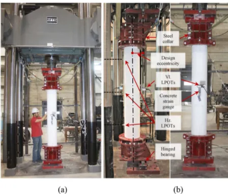
Figure 3.2– Test setup. 33
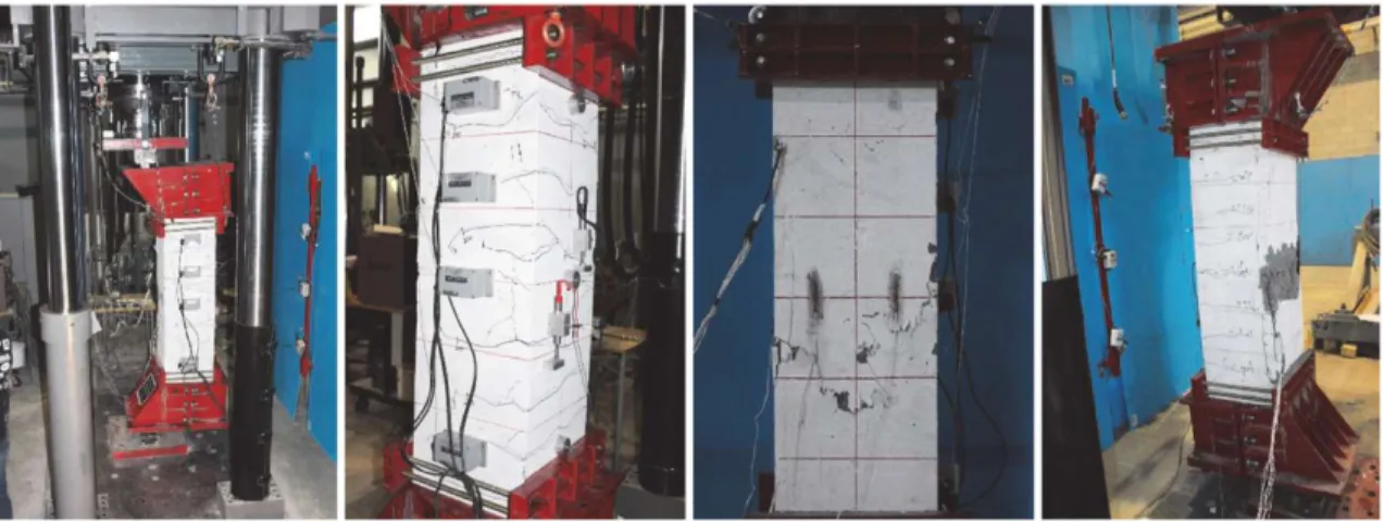
Figure 3.3– Typical failure modes: (a) Compressive rupture of GFRP bars; (b) tensile rupture of GFRP spirals; and (c) failure shear plan.. 35 Figure 3.4– Axial stress-axial strain response (Note: 1 MPa = 145.04 psi). 36 Figure 3.5– −(a) Mid-height lateral displacement; (b) Axial strain gradient at loading and unloading faces and mid-height lateral displacement of specimen G5-33. (Note: 1 mm = 0.0394
in.; 1 kN = 0.225 kpi). 38
Figure 3.6– Loads versus longitudinal-bar strain curves. (Note: 1 kN = 0.225 kpi). 41 Figure 3.7– Euler-Johnson’s failure envelope. 45
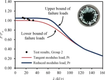
Figure 3.9– Verification of the theoretical buckling loads against test results. 50 Figure 3.10– Effect of considering FRP-bar contribution on the tangent modulus loads. 51 Figure 3.11– Maximum slenderness limit of material failure. 52 Figure 4.1– (a) Reinforcement details, GFRP cages, and internal instrumentation, (b)
Sand-coated GFRP bars and spirals. 62
Figure 4.2– Testing plan: (a) Connecting the external instrumentation, (b) Test-setup
components. 65
Figure 4.3– Failure modes. 68
Figure 4.4– Normalized applied load: (a) Concrete compression strain. (b) Tension-bar strain. (c) Compression-bar strain, (d) Axial-displacement response at mid-height. 69 Figure 4.5– Experimental buckling profile for the GFRP-reinforced concrete columns. 72 Figure 4.6– Experimental normalized load–normalized bending envelopes for slender
GFRP-RC columns. 75
Figure 4.7– (a) Pin-ended column bent in a single curvature, (b) Column cross-section, (c)
Concrete stress–strain model. 77
Figure 4.8– Schematic flowchart for the analysis process. 78 Figure 4.9– Verification of the theoretical interaction diagram with test results considering
2nd-order effects. 79
Figure 4.10– Effect of load eccentricity ratio on the strength curves of GFRP-reinforced
concrete columns. 81
Figure 4.11– Definition of material and stability failures. 82 Figure 4.12– Proposed slenderness upper limit for GFRP-reinforced concrete columns on the
basis of ACI 2019 provisions. 83
Figure 4.13– Comparison of the proposed and current slenderness lower limits. 83 Figure 4.14– Normalized applied load versus the load eccentricity ratio. 85 Figure 4.15– Concrete and GFRP reinforcing bars contribution to the ultimate capacity of the GFRP-RC columns with various slenderness ratios. 85 Figure 5.1– Geometry, reinforcement details, and internal instrumentation. (Note: Dimensions
are in mm; 1 mm = 0.0394 in.). 94
Figure 5.2– Test setup and testing machine. 97
xv
Figure 5.4– Normalized applied load versus: (a) concrete compression strain at mid-height; (b) axial-displacement response; and (c) longitudinal-bar strain. (Note: 1 mm = 0.0394 in.)
100 Figure 5.5– Mid-height linear-strain distribution over the column cross section at peak load. 103 Figure 5.6– Axial-strain gradient and mid-height lateral displacement of specimen GA-33-C.
(Note: 1 mm = 0.0394 in.). 105
Figure 5.7– Effect of test parameters on the buckling profile for the GFRP-RC columns. (Note:
levels are in mm; 1 mm = 0.0394 in.). 105
Figure 5.8– (a) Effect of the applied initial eccentricity on column ultimate bearing capacity; (b) experimental normalized load–normalized bending envelopes for slender GFRP-RC
columns. 107
Figure 5.9– Effect of spiral pitch on the spiral-strain response for concentric and highly eccentric loading on slender GFRP-RC columns . 109 Figure 5.10– (a) Deflected shape for an ideally hinged column bent in a single curvature; (b) GFRP-linear stress–strain diagram; (c) concrete stress–strain model; (d) A strip-by-strip
cross-sectional analysis. 111
Figure 5.11– Verification of the analytical failure envelope with the experimental results. 113 Figure 5.12– Impact of longitudinal-reinforcement ratio and Modulus of Elasticity of GFRP-bars on the P–M interaction diagram with various slenderness ratios. (Note: 1 GPa = 145.04
ksi). 114
Figure 5.13– Analytical strength curves of GFRP-RC columns. (Note: 1 GPa = 145.04 ksi). 115 Figure 5.14– Lateral displacement-to-initial eccentricity ratio versus column slenderness ratio.
(Note: 1 GPa = 145.04 ksi). 116
Figure 5.15– Lateral displacement-to-initial eccentricity ratio versus column slenderness ratio.
(Note: 1 GPa = 145.04 ksi). 117
Figure 6.1– Specimen design, strain-gauge arrangement, and sand-coated GFRP bars and
spirals. 126
Figure 6.2– (a) GFRP cages, (b) casting, (c) testing and test setup, (d) concrete cores. 127 Figure 6.3– Failure modes (after loads were released). 130
Figure 6.4– Applied load versus: (a) axial shortening, (b) concrete compression strain. (c) mid-height lateral displacement, (d) GFRP-spiral strain. 132 Figure 6.5– Strain gradient at first peak load. 133
Figure 6.6– GFRP-bar strain response. 133
Figure 6.7– High eccentric loaded slender HSC columns before releasing the applied load. 135 Figure 6.8– Experimental induced buckling profile. 137 Figure 6.9– Effect of P–δ response on the induced second-order effects at different
eccentricities. 138
Figure 6.10– Experimental interaction envelopes for slender GFRP-RC columns. 139 Figure 6.11– Effect of concrete strength on column strength at different eccentricity levels. 140 Figure 6.12– (a) Pin-ended column bent in a single curvature, (b) column cross section, (c)
concrete stress–strain models. 145
Figure 6.13– Strip-by-strip cross-sectional analysis. 148 Figure 6.14– Verification of the theoretical peak load considering second-order effects with
test results. 150
Figure 6.15– Effect of HSC and eccentricity ratio on column strength curves at L 1%. 151 Figure 6.16– Effect of HSCs on the slenderness limit at 5% strength reduction. 152 Figure 6.17– Effect of implementing HSC on the developed interaction diagrams at different
slenderness ratios. 154
Figure 6.18– Normalized load versus eccentricity ratio of HSC columns at various slenderness
ratios. 154
Figure 7.1– (a) Pin-ended column model; (b) Real cross-section; (c) Assumed equivalent
cross-section 167
Figure 7.2– Typical P-M interaction diagrams of GFRP-RC cross-section and column analysis. 168
Figure 7.3– Typical P-M-φ curves. 170
Figure 7.4– Typical failure modes and test setup. 174 Figure 7.5– Rupture of GFRP-bars and spirals. 175 Figure 7.6– Moment-curvature behavior of the tested GFRP-RC columns. 177
xvii
Figure 7.7– Verification of the analytical model with the test results. 177 Figure 7.8– Typical cross-sections of GFRP-RC columns considered in the parametric study. 179 Figure 7.9– Comparison of theoretically-based flexure stiffness with ACI stiffness equations. 180 Figure 7.10– Effect of test parameters on the flexural stiffness of GFRP-RC columns. 180 Figure 7.11– Effect of test parameters on the concrete compression-zone depth;(a) λ = 30,
40 MPa
c
f
,Efrp 60 GPa;(b, c, and d) ρ = 2%,f
c
40 MPa
,Efrp 60 GPa. 183Figure 7.12– Definition of material and stability failure modes. 183 Figure 7.13– Comparison of the proposed flexural stiffness with the theoretical results. 186 Figure 7.14– Verification of the proposed flexure stiffness equation with the theoretical results. 188 Figure 7.15– Effect of the cross-section geometry and GFRP-bars configuration on the
List of Tables
Table 2.1 – Slenderness limits in North American Codes 15 Table 2.2 – Comparison of Stiffness Modifications in Steel-RC and FRP-RC. 20 Table 3.1 – Test matrix, specimens’ details, and test results 31 Table 3.2 – Mechanical and physical properties of the GFRP and steel reinforcement 31 Table 3.3 – Proposed effective flexural stiffness from literature1 44
Table 4.1 – Test specimens and results 63
Table 4.2 – Mechanical and physical properties of the GFRP and steel reinforcement 63 Table 5.1 – Mechanical properties of the GFRP reinforcement 93
Table 5.2 – Test matrix and results 95
Table 6.1 – Test matrix and results 126
Table 6.2 – Concrete compressive strength (1) 127
Table 6.3 – Mechanical properties of the GFRP reinforcement 128 Table 6.4 – Mechanical properties of the GFRP reinforcement 144
Table 7.1 – Test matrix and results 173
Table 7.2 – Mechanical properties of the GFRP reinforcement 174
CHAPTER 1
I
NTRODUCTION
1.1
General Background
Reinforced concrete (RC) columns can be classified into two broad categories: short columns and slender columns. Slender columns experience considerable reduction in the column capacity due to the induced column buckling compared to the capacity of short or stocky columns that fail without undergoing any noticeable lateral deformations. Most of columns are preferred to be short to eliminate any losses due to lateral deformations and to achieve the maximum loading resistance. However, slender columns are common nowadays because of rapid development of the high strength materials and improved methods of erection which enabled for design some much smaller sections than in the past. Figure 1.1 shows some examples of slender columns in various applications.
Figure 1.1– (a) Viaduct St. Kilian, Germany (structurae.net); (b)University of Magdeburg Library, Germany (designbuild-network.com); (c) Estádio Nacional Mané Garrincha, Brazil
To overcome the tensile stresses caused by the existing loads, misalignments, and/or lateral buckling and second-order effects, such columns are usually reinforced with conventional steel bars and spirals or ties. Steel reinforcement has a limited service life and entails high maintenance costs because of corrosion when used in aggressive and/or harsh marine environments. Therefore, reinforcing slender RC columns with FRP reinforcement extends the structure’s lifetime span and can eliminate the high repair and rehabilitation expenditures due to the inevitable corrosion of conventional steel. For example, the US Federal Highway Administration (FHWA) reported that, in 2018, the estimated rehabilitation costs of structurally deficient (SD) national and nonnational highway system bridges due to steel corrosion exceeded $32.8 billion. Furthermore, the Canadian Construction Association (CCA) estimated that the investment required to rehabilitate public infrastructure overall hovers around C$900 billion (ISIS Canada 2007).
Current editions of North American design codes include comprehensive sections dealing with the design of slabs and beam members reinforced with GFRP-bars. Yet, current standards either do not recommend integrating FRP bars into compression members (ACI 440.1R-15) or conservatively ignore their contribution to the capacity of such members (AASHTO 2018; CSA S806-12). Furthermore, CSA S806-12 stipulates that slender columns shall not be permitted to have FRP longitudinal reinforcement. Consequently, enormous efforts are being deployed to provide detailed sections dealing with the design of GFRP-RC columns in upcoming editions of FRP design codes. This, in turn, requires a large experimental database to assess the behavior of short and long GFRP-RC columns and to propose rational design limits to the code technical committees. Consequently, this research intended to assess the performance of FRP reinforcement in slender columns, accounting for the induced second-order effects. Furthermore, the moment magnifier approach permitted in ACI 318-19 and CSA A23.3-14 for the design of steel-RC slender columns, was re-examined to accommodate FRP reinforcement through proposing design limits, equations, and general recommendations.
1.2
Objectives and Scopes
This research program attempted to provide comprehensive tests and analytical investigations of slender GFRP-RC columns in order to support the work of the relevant technical committees.
1.2 Objectives and Scopes 3
The performance of GFRP bars and spirals were observed through strain measurements at different locations including the most stressed zones. Moreover, the impact of various slenderness ratios on the failure envelope and second-order responses were clearly highlighted and well-presented. Further, the test results of GFRP-RC slender columns were compared with steel-RC counterparts prepared and tested in the same testing conditions as GFRP-RC ones. Therefore, the main and general objective of this study can be drawn as:
Addressing the feasibility of integrating GFRP bars as an internal reinforcement of RC slender columns, proposing design provisions for the relevant North-American codes and guidelines. Besides, the following points summarize the specific objectives:
1. To assess the general behavior of slender GFRP-reinforced concrete columns with critical slenderness ratios ranging from
14
to
33
under concentric and different levels of eccentric loading.2. To quantify the capacity of slender GFRP-reinforced concrete columns, identifying the strength reduction owing to initiated second-order effects.
3. To develop a P–M failure surface of slender GFRP-reinforced concrete columns reflecting the influence of second-order effects on the failure paths.
4. To propose recommendations for slenderness lower and upper limits for GFRP-reinforced concrete columns that could support the work of the North American technical committees engaged in developing standards and design provisions for GFRP-reinforced concrete columns.
5. To experimentally assess the moment-curvature relationship of GFRP-RC slender columns, identifying the influence of the different test parameters on the column flexural stiffness. 6. To develop EI design equations for GFRP-RC slender columns that could generalize the
1.3
Methodology
The above objectives were gained through conducting a large-scale research plan including experimental program and theoretical studies. The experimental plan was consisted of 34 RC columns entirely reinforced with GFRP bars and spirals. All columns are 305-mm in diameter with various heights (1000-mm, 1250-mm, 1750-mm, 2000-mm, and 2500-mm). In addition to the slenderness ratio as a studied parameter, a further set of variables will be investigated such as longitudinal reinforcement ratio, confinement level, and the load eccentricity ratio. Two batches of ready-mixed, normal-weight concrete were used to cast the column specimens: one was for normal-strength concrete; the other was high-strength concrete. As designers are more familiar with the behavior of steel-RC columns, a total of 4 RC columns reinforced with steel reinforcements were prepared and tested at the same testing conditions of GFRP-RC ones to be served as a benchmark.
Any experimental work is going to be of limited usefulness unless it is utilized to develop some simplified design equations. Consequently, a detailed theoretical analysis was carried out in conjunction with the experimental findings to develop models capable to clearly define the behavior of the slender columns reinforced with GFRP. Developed models considered both material and geometrical nonlinearities of GFRP-RC columns. Therefore, these models were capable to predict and simulate the second-order effects attributed to slender columns. Thereafter, the analytical models were verified with the experimental results of the current study and with the experimental database from literature. The analytical models were then employed to extend the research program over a wide range of parametric values including the elastic modulus of GFRP-bars, the column cross-section geometry, and GFRP-bars arrangement in addition to the above-mentioned variables in the experimental program. At last, a multiple linear regression analysis was conducted of the simulated theoretical data in order to propose a simple and practical design equation of the effective flexural stiffness of GFRP-RC slender columns.
1.4 Thesis organization 5
1.4
Thesis organization
The thesis is organized into eight chapters including the introduction. As usual, the thesis begins commonly with an introduction defining the research objectives and methodology as described earlier. Thereafter, A short review is presented in Chapter 2 to provide the reader with most research studies related to the aimed objectives. The next chapters are arranged as follows:
Chapter 3 (1st article) presents an experimental and theoretical investigation of GFRP-RC
columns with various slenderness ratios under concentric axial loads with a focus on stability problems. An estimation of the axial capacity of slender FRP-RC columns along with a new slenderness limit are also proposed based on the experimental results and the buckling analysis. Chapter 4 (2nd article) presents test results of an experimental program to investigate the
structural performance of slender columns loaded at different eccentricities. Based on the test results, a detailed second-order analysis were then conducted. Furthermore, a comprehensive parametric investigation was performed using interaction diagrams and stability curves. Chapter 5 (3rd article) presents a detailed experimental study to discuss the effect of different
test parameters on the second-order response of GFRP-RC slender columns. In addition, based on the stability index specified in ACI 318-19, the maximum permissible tensile design strain of the GFRP-bars was proposed to eliminate the probability of the undesired stability failure of such columns.
Chapter 6 (4th article) investigated experimentally and analytically the feasibility of
high-strength concrete (HSC) in circular GFRP-RC columns under concentric and eccentric loading. The proposed slenderness limit was verified and required modifications have been applied to account for the effect of using HSC on the slenderness lower limit.
Chapter 7 (5th article) introduces a 2nd-order analytical model was derived to assess the
structural performance of more than 9,500 GFRP-RC slender columns includng a wide range of design parameters. The model was used to re-examine the moment magnifier approach
specified in ACI 318 for the structural analysis of steel-reinforced concrete (RC) slender columns to accommodate glass fiber-reinforced polymer (GFRP)-RC columns.
The last Chapter of the thesis, Chapter 8, presents some detailed conclusions of the results obtained from the experiments and analyses with respect to observations and highlights discussed throughout the thesis in addition to recommendations for future work.
CHAPTER 2
L
ITERATURE REVIEW
2.1
General
RC columns are considered as the most substantial element in any RC structure and failure of one column may be an adequate reason for the whole building collapse. Consequently, extensive studies have been carried out in order to assessing the behavior of steel-RC columns. However, limited research was directed to investigate the behavior of fiber-reinforced polymers (FRP)-RC columns, especially slender ones. In addition to the literature review provided in each chapter, the following sections provide a short review of the relevant studies in literature, emphasizing the general behavior and design aspects.
2.2
Performance of FRP-RC Columns
In general, the behavior of FRP-RC columns was found to be similar to those columns that are reinforced with traditional steel bars (De Luca et al. 2010; Tobbi et al. 2012; Afifi et al. 2014; Mohamed et al. 2014; Hadhood et al. 2017a, b, c, and d). For example, Fig. (2.1) is adopted from Hadhood et al. (2017a) and presents the load-axial deformation relationship of two groups of columns. One group was reinforced with CFRP-bars and the other one was reinforced using traditional bars. This plot illustrates the very close performance of both CFRP- and steel-RC tested columns where no major discrepancies were observed. Moreover, the failure of the tested FRP-RC short columns in literature was typically dominated by a material-type failure in terms of gradual concrete cover spalling at the peak load (Hadi et al. 2016; Hassan et al. 2017) as shown in Fig. (2.2). Prior to the point of peak load, the initial applied eccentricity
eccentricity is, the less of the elastic loading path occur. Finally, FRP-bars were found to have a significant contribution to the column axial and flexural capacities of such FRP-RC columns (Tobbi et al. 2012; Tobbi et al. 2014; Afifi et al. 2014).
Figure 2.1– Load versus axial displacement at specimen centerline (Hadhood et al. 2017a).
Figure 2.2– Failure modes of the tested specimens (Hadi et al. 2016).
In most cases, FRP-bars behave elastically up-to failure at large tensile strains exceeds 0.02 compared to a steel yield-strain equals 0.002. These large tensile strains related to FRP-bars (which is approximately 10 times of yielding strain of steel bars) causes that most of the tested
2.2 Performance of FRP-RC Columns 9
specimens in labs fails in compression before reaching the FRP-failure tensile strains. However, some researchers (Hadhood et al. 2017a; Guérin et al. 2018a, b) reported that the tested high-eccentrically loaded columns suffered exaggerated tensile cracks accompanied with large deformations before concrete cover spalling occurred. Fig. (2.3) shows the cracking pattern and failure mode of the GFRP-RC columns tested by Guérin et al. (2018a). The shown test specimen was loaded at an eccentricity-to-depth ratio of 0.80. As ACI 318-14 defines the tension failure as that failure at which a sufficient warning is achieved in terms of excessive tensile cracks and large curvature. Similarly, failure of FRP-RC columns loaded at large eccentricities can be defined as a tension-based failure.
Figure 2.3– Crack appearance and failure mode of columns tested under large eccentricity (e/ho = 80%; G2) (Guérin et al. 2018a).
As mentioned earlier, FRP-bars do not yield and have an elastic behavior up-to failure (ACI 440.1R-15). This affected the achieved ductility of FRP-reinforced columns compared to steel counterparts. However, studies in literature showed that such FRP-RC columns still have the ability to attain adequate deformations even after achieving the peak loads or spalling of the concrete cover at compression side (Pantelides et al. 2013; Afifi et al. 2014; Mohamed et al. 2014). Therefore, the term of “deformability factor” was introduced to define the latter behavior of FRP-RC after failure (ISIS 2007). The ductility and confinement efficiency of the concrete core can be effectively improved using smaller FRP-spirals with closer spacing. Such confinement configuration causes the FRP-RC columns to fail in more gradual manner,
enhancing the ductile behavior in the post-peak stage as concluded by Afifi et al. (2014) and Mohamed et al. (2014). Afifi et al. (2014) defined the ductility of the tested GFRP-RC columns as the ratio c85 c1, where c85is the axial strain defined at an axial load corresponding to 85% of the maximum loading capacity in the descending part of the load–strain curve (see Fig. 2.4), and c1 is defined at a strain corresponding to the limit of elastic behavior on the ascending part.
Figure 2.4– Ductility of the GFRP RC columns on the basis of strain measurements (Afifi et al. 2014).
Several studies have been published recently by a research group in University of Wollongong on the behavior of GFRP-RC columns under axial and/or eccentric loading (Hadi and Youssef 2016; Hadi et al. 2016 and 2017; Karim et al. 2016). These studies include experimental and analytical investigations of various parameters. The experimental program used square cross section of 210 mm sides and 800 mm height and/or circular sections of diameter 205 mm and height 800 mm. The specimens tested under concentric loading; eccentric loading of 25 mm and 50 mm; and/or two-point loading flexure. The test variables were the type of reinforcement (steel vs. GFRP); external confinement or none; internal reinforcement or none; normal concrete or fiber-reinforced concrete. The analytical program included developing interaction diagrams; parametric studies; estimation of ductility.
Their concentric GFRP-RC specimens exhibited second peak points indicating proper confinement, provided by helices spaced each 30 mm or 60 mm. The closely spaced specimen exhibited, however, higher second peak than the other (Hadi et al. 2016). They reported that
2.2 Performance of FRP-RC Columns 11
reducing the GFRP helices pitch from 60 to 30 mm led to an improvement in the performance of the GFRP-RC specimens in terms of load-carrying capacity, bending moment, and ductility. They also reported that the contribution of the longitudinal steel bars in the load carrying capacity of the concentric column specimens was about twice the contribution of the longitudinal GFRP bars, whereas the ductility of the GFRP-RC column specimens was slightly greater than the ductility of the reference steel-RC column specimens under different loading conditions.
Limited available experimental results discussed the behavior of FRP-RC slender columns. Tikka et al. (2010) conducted an experimental program to investigate the behavior of eccentrically loaded slender columns reinforced longitudinally by GFRP bars and laterally tied by Carbon Fiber spirals. Eight square columns 150 mm width with 1800 mm total height were tested. The test variables are the reinforcement ratio and the supplier. Two reinforcement ratios are studied 2.3%, and 3.4%. Also, two sets based on the suppliers were arranged. Figure (2.5) shows the specimens and testing details. The results from this study showed that using GFRP bars from two different manufacturers provided very similar strengths. The plotted load-deflection curves of the tested specimens revealed that GFRP-RC columns had a reasonable amount of ductility and would provide adequate warning perior to failure.
Hales et al. (2016) tested nine high-strength concrete (90 MPa) columns reinforced using either GFRP-bars or steel-bars or a combination of both. The tested columns had slenderness ratios (heights) equalled to 10 (760-mm) and 49 (3730-mm). The reduction in the loading capacity due to slenderness variations could not be observed as the short and long columns had different loading conditions. It was reported that the strength of slender columns with small eccentricity (8.3% of the column size) was governed by material-type failure, while that of slender columns with large eccentricity (33% of column size) was governed by a stability-type buckling failure. Also, GFRP longitudinal reinforcement can provide larger deflection capacity compared to steel bars due to their higher tensile strength; in addition, they retrieved its original shape once the load is removed, which can be beneficial in case of earthquakes. Fig. 2.6 shows the failure mode of the slender column due to 102 mm eccentric load.
Figure 2.6– Slender Columns Tested to Failure (102-mm eccentricity): (a) Before Failure; (b) After Failure.
Recently, Xue et al. (2018) conducted concentric and eccentric loading tests on slender rectangular GFRP-RC columns. Columns were tested under a wide range of the applied eccentricity-to-depth ratios varied from 0 to 1.0. The slenderness ratio of the tested columns
2.3 Design for FRP-RC Columns 13
ranged from 20.8 to 41.6. The test results from Xue et al. (2018) indicated that All columns failed by concrete crushing followed by spalling of the concrete and eventually buckling of the GFRP bars on the compression bars near the mid-height, as shown in Fig. (2.7). The exhibited concrete crushing was in a brittle manner, even for the column with low longitudinal FRP reinforcement ratio (1.34%), large eccentricity ratio (1.0), and high slenderness ratio (41.6). Furthermore, very little post-peak deformation was observed. All GFRP-bars remained intact up-to concrete crushing and the failure load was achieved. As expected, columns with large load eccentricity cracked and deformed significantly prior to failure.
Figure 2.7– Typical failure mode of columns (Xue et al. 2018).
2.3
Design for FRP-RC Columns
Design of any FRP-RC column can be generally divided into two main stages. Stage one defines the exact analysis of the structure considering the applied loads and the induced deformations of the structure due to sidesway and/or slenderness effects. This (stage one) is called as a second-order analysis. The next stage is to find an adequate section to resist the
applied loads and the loads from the second-order effects. The latter stage is established and well-addressed by many codes and guidelines. Regarding stage one, it is beneficial to point out that integrating the structure into a rigorous second-order analysis is a time-consuming process and not suitable for repetitive designs. Therefore, MacGregor et al. (1970) stated that 5% reduction in the column capacity due to second-order effects was acceptable and additional moments from second-order effects may be neglected. For such cases, columns may be designed as short columns satisfying the first-order analysis.
ACI 318-19 and CSA A23.3-14 applied the latter definition originally defined by MacGregor et al. (1970) to set a slenderness limit below which second-order effects on steel-RC columns can be safely ignored. ACI and CSA guidelines express the mechanical slenderness ratio ( klu/ )r in terms of the unsupported length of the column (l ); the effective length factor, u
k ; and the radius of gyration of its cross section, r Ig/Ag, where Ig and Ag are the gross
second moment of inertia and the gross cross-sectional area of the column, respectively. Regarding steel-RC columns, the earlier mentioned codes stated that a slender lower limit of 22 is a safe limit for short columns bent in a symmetrical single curvature. Table 2.1 compares the different slenderness limits stipulated in the North American codes and standards. The upper limit for the slenderness ratio provided by ACI is to eliminate the probability of any undesired stability failure. Limited efforts have been directed to define similar slenderness limit dealing with columns entirely reinforced with FRP-bars. The following section summarizes these attempts.
2.3.1
Slenderness Limits of FRP-RC columns
As mentioned before, two slenderness limits govern the design of FRP-RC columns: lower and upper slenderness limits. So far, there is not any attempt to define an upper slenderness limit for FRP-RC columns. Regarding the lower slenderness limit, CSA S806-12 classifies GFRP-RC columns as short or long, relying on the ACI slenderness limit of 22 for steel-GFRP-RC columns, disregarding that FRP-reinforced concrete members might resist buckling instability differently than steel-reinforced ones. Moreover, CSA S806-12 allows for using FRP-bar as an internal reinforcement for short columns only and explicitly prohibited using it for slender columns. This undoubtedly is due to the lack of the experimental results.
2.3 Design for FRP-RC Columns 15
Table 2.1 – Slenderness limits in North American Codes
Margins Member and condition ACI 318-14 CSA A23.3-04 (2010)
Lower limit
Columns not braced against sidesway and individual compression members. 𝑘 𝑙 𝑟 ≤ 22 𝑘 𝑙 𝑟 ≤ 35 𝑃⁄ 𝑓 𝐴
Columns braced against sidesway. 𝑘 𝑙 𝑟 ≤ 34 − 12(𝑀 𝑀⁄ ) and 𝑘 𝑙 𝑟 ≤ 40 𝑘 𝑙 𝑟 ≤ 25 − 10(𝑀 𝑀⁄ ) 𝑃⁄ 𝑓 𝐴
Upper limit All compression members
𝑀 ≥ 1.4 𝑀 𝑘 𝑙
𝑟 ≥ 100 Beyond this limit the
structural system should be revised.
Beyond this limit, more accurate analysis should be
performed.
Mirmiran (1998) developed an analytical model to investigate the slenderness effect on FRP-RC concrete columns. The developed model accounted for the constitutive properties of materials including concrete, steel and FRP rebar. The studied parameters considered the compressive-to-tensile strength ratio of FRP rebar. The second-order effect was also implemented in the model by integrating deflections over the length of the column. The model was validated with 4 square CFRP-RC columns with 152 mm sides. He reported that slenderness limits shall be reduced by 5%, 15% and 22% for aramid, carbon and glass rebar, respectively, if the minimum reinforcement ratio is held at 1%. Later, Mirmiran et al. (2001) carried out an analytical study by making 11,000 columns to investigate the effect of internally reinforced FRP bars on the slenderness limits and to examine the applicability of ACI moment magnification to FRP-RC columns. A 254 x 254 mm2 section with 27.6 MPa concrete was
considered for the parametric study. The chosen parameters were reinforcement ratios, modular ratios, strength ratios, compressive to tensile strength ratios, yielding response of reinforcing bars, slenderness ratios, end eccentricities, and eccentricity ratios to investigate the effect of
internally reinforced FRP bars on the slenderness concrete column. Figure 2.8 to Figure 2.10 show the effect of strength ratio, compressive/tensile strength ratio, and reinforcement yielding on the columns’ slenderness limit. The following conclusions were made:
1. Variation in tensile strength of typical FRP bars does not affect the slenderness limit of RC columns;
2. Except for aramid bars that have very low compressive strength, variation in compressive strength of FRP bars does not affect the slenderness limit of RC columns. Lower compressive strengths result in more stable columns; and
3. The yielding phenomenon of reinforcing bars does not affect the slenderness limit of RC columns.
4. Based on the parametric studies, it is recommended that the current slenderness limit of 22 for steel-RC columns bent in single curvature be reduced to 17 for FRP-RC columns.
2.3 Design for FRP-RC Columns 17
Figure 2.9– Effect of Reinforcement Yielding on Slenderness Limit (Mirmiran et al., 2001).
Figure 2.10– Slenderness Limit Versus Compressive/Tensile Strength Ratio, (Mirmiran et al., 2001).
Jawahery Zadeh and Nanni (2017) applied a theoretical derivation for the slenderness limits of FRP-RC columns with a rectangular cross section. The contribution of FRP bars in compression was limited to the concrete compressive strength. This means that the area of FRP-bars in compression was replaced by concrete. This was considered as a safe and justifiable hypothesis between two extremes of either subtracting the area of FRP-bars from the gross cross-sectional area or consider the full contribution of the FRP-bars in compression based on equivalent tensile and compressive moduli of elasticity. Finally, they proposed a slenderness limits of 14 and 19 for GFRP-RC and CFRP-RC columns bent in a symmetrical single curvature, respectively. These slenderness limits are considered as more conservative compared to those proposed by Mirmiran et al. (2001)
Karim et al. (2017) conducted a numerical integration to determine the compression force of the concrete in the compression zone of GFRP-RC cross-sections. The results were verified with 12 circular GFRP-RC specimens. All test specimens had a slenderness ratio of 15.6. however, they extended the research program to investigate the influence of column slenderness ratio on the behavior of GFRP-RC columns. At 5% strength reduction, Karim et al. (2017) proposed a slenderness limit of 18.7 below which GFRP-RC columns may be designed as short. The authors explained the higher proposed value of the slenderness limit compared to that reported by Mirmiran et al. (2001) as the latter used GFRP-bars had a relatively low elastic modulus. Recalling Fig. 2.8, the strength ratio on horizontal axis was defined as the ratio of tensile strength of FRP bars (or yield strength of steel bars) and compressive strength of concrete. Based on the current available GFRP-bars on markets, this strength ratio varies between 18 to 27 and 33 to 50 considering a concrete compressive strength of 55 MPa and 30 MPa, respectively. According to Mirmiran’s analytical study, it could be noticed that beyond a strength ratio of 20 both the modular and strength ratios have a trivial effect on the slenderness limit particularly for columns bent in a symmetrical single curvature. The modular ratio is defined as the ratio of moduli of elasticity of the reinforcement and concrete, and ranges (considering GFRP-bars on market) between 1.55 to 2.33 and 1.15 to 1.72 for 30 MPa and 55 MPa normal-strength concrete, respectively. Finally, the scattering in the proposed values of the slenderness limit of FRP-RC columns in literature accentuates the need for more experimental and analytical studies to be conducted.
2.3 Design for FRP-RC Columns 19
To sum up, the design of FRP-RC columns starts with checking the column as being whether short or long. Once the column category is defined, one of the following design approaches can be established.
2.3.2
Short FRP-RC Columns
As mentioned earlier, FRP-RC columns have slenderness ratio less than the slenderness lower limits can be designed as being short, satisfying the 1st-order analysis. Strength of such columns
is governed by the strength of the used materials and the column cross-section geometry. Several studies proved the significant contribution of FRP-bars in compression. The compression contribution of the GFRP-bars to the column axial capacity prior to concrete spalling was reported to be ranged from 2.9% to 4.5% (De Luca et al. 2010), with 5% to 10% (Afifi et al. 2014), and 6.6% to 10.5% (Maranan et al. 2016) for reinforcement ratios of 1%, 2.2%, and 2.4%, respectively. However, CSA S806-12 offers a conservative expression to determine the axial capacity of FRP-RC columns. The offered formula not only ignores the contribution of FRP-bars in compression but also subtract the area of FRP-bars from the total gross concrete area of the column’s cross-section. Afifi et al. (2014) reported that ignoring the contribution of FRP longitudinal bars in the CSA S806-12 design equation underestimated the maximum capacity of the tested specimens on average by 35%.
Tobbi et al. (2012) reported that setting the FRP compressive strength at 35% of the FRP maximum tensile strength yielded a reasonable estimate of the ultimate compressive capacity of FRP-RC short columns compared to the experimental results. Afifi et al. (2014) described the latter recommendations as an accurate and a conservative prediction of the nominal capacity of the tested GFRP-RC columns. Jawahery Zadeh and Nanni (2013) showed that it is possible to develop a methodology for the design of concrete columns with rectangular or circular cross section using GFRP bars and ties. This can be achieved by discussing the theoretical approach at the basis of the behavior of GFRP-RC members subject to simultaneous flexural and axial loads. It was concluded that:
1. The authors developed Interaction diagrams assuming that GFRP longitudinal bars are only effective in tension. It’s suggested to limit the maximum design strain of GFRP longitudinal bars to be 0.01 to avoid exaggerated deflections.
2. They proposed modification factors for the flexural stiffness of GFRP-RC members which are based on the modulus of elasticity of GFRP bars. The proposed design provisions in this paper are not applicable to structures in seismic zones and may be applicable only to buildings of limited size and height.
The authors proposed stiffness modifications to the values presented in ACI 318-19 for steel- reinforced columns to represent the behavior of the same columns if the latter were reinforced with FRP. These values were slightly modified by the same authors in 2017 (Jawahery Zadeh and Nanni 2017). Table 2-2 shows a summary of these modifications.
Table 2.2 – Comparison of Stiffness Modifications in Steel-RC and FRP-RC. Steel-RC (ACI
318-19) Proposed for FRP-RC (2013) Proposed for FRP-RC (2017) Ibeam = 0.35 Ig Ibeam= [0.075 + 0.275(Ef/Es)] Ig ≤ 0.35Ig Ibeam = [0.10 + 0.25(Ef/Es)] Ig ≤ 0.35Ig Islab = 0.25 Ig Islab= [0.10 +0.15(Ef/Es)] Ig ≤ 0.25Ig Islab = [0.10 + 0.15(Ef/Es)] Ig ≤ 0.25Ig Icolumn = 0.70 Ig Icolumn= [0.40 + 0.30(Ef/Es)] Ig ≤ 0.70Ig Icolumn = [0.40 + 0.15(Ef/Es)] Ig ≤ 0.55Ig
2.3.3
Slender FRP-RC Columns
As the building deflects laterally, gravity loads acting on the building produce additional moments and forces in the structure. When these effects are considered in the structural analysis of the building, the analysis is referred to as “second-order analysis”. If the second-order analysis uses nodes along compression members, the analysis accounts for slenderness effects due to lateral deformations along individual members, as well as sidesway of the overall structure. If the second-order analysis uses nodes at the member intersections only, the analysis
2.3 Design for FRP-RC Columns 21
captures the sidesway effects for the overall structure but neglects individual member slenderness effects (ACI 318-19). In this case, individual member slenderness effects should be calculated and added to the analysis results. Again, applying a second-order analysis is a time-consuming process and is not preferred from designers in repetitive office work. Therefore, many codes and guidelines offer simpler approaches for the design of slender columns.
ACI 318-19 and CSA A23.3-14 permit considering a first ̵ order analysis results for design, while the impact of member slenderness (i.e., effect of lateral deformations of an individual member) and sidesway effects for the overall structure should be calculated and added to the analysis results. In the literature, two approaches have been considered to include slenderness effects in column design; applying a reduction factor to the load carrying capacity of a short column or the moment magnifying approach. The latter approach is recommended by the recent codes and guidelines for the design of steel-RC slender columns. In order to account for reflecting the degree of cracking, creep due to sustained loads, and inelastic actions that have occurred along each member, effective member stiffness should be used in such analysis. Limited attempts have been exerted to accommodate the moment magnifier approach addressed in ACI 318-19 and CSA A23.3-14 to the FRP-RC columns (Mirmiran et al. 2001; Jawahery Zadeh and Nanni 2017; Xue et al. 2018). A comprehensive review of the moment magnifier approach and the previous attempts conducted to propose an effective lateral flexural stiffness of steel- and FRP-RC slender columns, is presented in Chapter 7.
CHAPTER 3
Proposed Slenderness Limit for GFRP-RC Columns
Based on Experiments and Buckling Analysis
Proposition de l’élancement limite pour les poteaux en béton armé de prfv
basée sur des essais expérimentaux et l’analyse du flambement
Foreword
Authors and Affiliation:
– Waseem Abdelazim is a doctoral candidate in the Department of Civil Engineering at the University of Sherbrooke, Sherbrooke, QC, Canada, J1K 2R1.
– Hamdy M. Mohamed is a research associate and lecturer in the Department of Civil Engineering at the University of Sherbrooke, Sherbrooke, QC, Canada, J1K 2R1.
– Mohammad Z. Afifi is a postdoctoral fellow in the Department of Civil Engineering at the University of Sherbrooke, Sherbrooke, QC, Canada, J1K 2R1.
– Brahim Benmokrane, FACI, is a Professor in the Department of Civil Engineering, Université de Sherbrooke, Sherbrooke, Quebec, Canada, J1K 2R1
Journal Title and Paper Status:
Published in ACI Structural Journal, V. 117, No. 1, January 2020.DOI: 10.14359/51718073 Contribution to the Thesis:
The study presented in the manuscript aims to establish for the first time a rational slenderness limit for design of concrete columns reinforced with GFRP bars and spirals based on experimental and theoretical results. This research study developed an experimental and theoretical investigation of GFRP-reinforced concrete columns with slenderness ratios of 14,
estimation of the axial capacity of slender GFRP- reinforced concrete columns along with a new slenderness limit are proposed based on the experimental results and the buckling analysis, that could support the work of the North American technical committees engaged in developing standards and design provisions for GFRP- reinforced concrete columns.
Abstract
In order to develop design provisions for concrete columns reinforced with fiber-reinforced polymer (FRP) bar for North American codes and guidelines (ACI 440.1R; CSA S806), a slenderness limit below which it is acceptable to ignore the induced second-order effects must be determined. Nevertheless, limited attempts have been made to define a safe slenderness limit for such columns. Therefore, this study aimed at experimentally and analytically investigating the buckling behavior of 12 full-scale concrete columns reinforced with glass FRP (GFRP) with slenderness ratios of 14, 17, 23, 26, and 33 under concentric loading. The impact of longitudinal reinforcement ratios and confining levels on the performance of slender glass-fiber-reinforced-polymer-reinforced concrete (GFRP-RC) columns is, also, presented. Test results indicate that the GFRP reinforcement contributed significantly to resisting the applied compression loads and resulted in failure modes similar to that of the counterpart steel-reinforced-concrete columns at different slenderness ratios. In addition, a theoretical buckling analysis considering a total of 50 test specimens, assembled from the current study and the literature, was developed to verify the applicability of Euler–Johnson’s stability envelope as well as the reduced and incremental modulus theories to FRP-RC columns. Good correlation was observed between the experimental results and the models developed analytically. Based on the experimental data and the developed buckling analysis, the safe limit of the slenderness ratio for FRP-RC columns bent in single curvature of 18 is proposed.
3.1
Introduction
Design Codes have not yet addressed stability and buckling issues related to slender concrete columns reinforced with fiber-reinforced polymer (FRP) bars owing to a lack of experimental data. Columns are defined as slender if they experience considerable reduction in the column
3.1 Introduction 25
capacity due to the induced column buckling compared to the capacity of short or stocky columns that fail without undergoing any noticeable lateral deformations. The reduction in the buckling load of slender columns is closely related to the maximum column failure load and can be significant, particularly for materials with a relatively low elastic modulus
E . Thedesign of slender columns requires that the deformed geometry of the structure be included in the equilibrium equations, that is, a second-order analysis. Second-order analysis is complicated and not practical for repetitive office design. Hence, MacGregor et al. (1970) stated that for steel-RC columns bent in a symmetrical single curvature, reduction in the column capacity due to second-order effects may be ignored if the column slenderness ratio
Le /r
is less than 22, where L is the column effective buckling length and er
is theradius of gyration of the column cross section. This slenderness limit corresponds to a 5% reduction in the column cross-section axial capacity. For such cases, the column could be safely designed as a short column satisfying the first-order analysis. ACI 318 and CSA A23.3 applied the latter definition along with an effective column lateral stiffness to set a slenderness limit
, below which steel-RC columns may be treated as being short. Regarding FRP-RC columns, CSA S806-12 allows the use of FRP reinforcement in short columns and conservatively ignores the contribution of FRP bars in compression. Moreover, CSA S806-12 classifies GFRP-RC columns as short or long, relying on the ACI 318 slenderness limit for steel-RC columns, disregarding that FRP-reinforced concrete members might resist buckling instability differently than steel-reinforced ones.
Over the last two decades, valuable extensive experimental and analytical research have been conducted to establish the behavior of concrete columns internally reinforced with FRP bars considering a wide range of parameters such as column cross section (square or circular), reinforcement type (glass or carbon), reinforcing bars from different suppliers (different batch effect), longitudinal-reinforcement ratios, confinement levels and configurations (spirals or ties), concrete compressive strength (normal- or high-strength concrete), loading type (concentric or eccentric), and so on (De Luca et al. 2010; Tobbi et al. 2012; Pantalides et al. 2013; Afifi et al. 2014; Mohamed et al. 2014; Hadi et al. 2016; Youssef and Hadi 2017; Hadhood et al. 2017a, b, c, and d; Guérin et al. 2018; Sheikh and Kharal 2018; Hadhood et al. 2019). Most of the experimental programs found in literature were performed for short columns