Faculté de génie Département de génie civil
BEHAVIOUR OF REINFORCED CFFT COLUMNS
UNDER AXIAL COMPRESSION LOADING
COMPORTEMENT AXIAL DE COLONNES EN BÉTON
ARMÉ RENFORCÉES DE TUBES EN MATÉRIAUX
COMPOSITES
Mémoire de maîtrise ès sciences appliquées Spécialité: génie civil
Asmaa Abd El daim Ibrahim Ahmed
A dissertation submitted in partial fulfillmentof the requirements for the degree of Master of Science
(Civil Engineering)
Jury: Prof. Radhouane MASMOUDI, Université de Sherbrooke (Directeur de recherche) Prof. Josée BASTIEN, Université de Laval (Examinateur)
Prof. Richard GAGNÉ, Université de Sherbrooke (Rapporteur)
ABSTRACT
The construction industry is expressing great demand for innovative and durable structural members such as bridge decks and piers, piling, and poles. Many steel-reinforced concrete structures subjected to de-icing salts and marine environments require extensive and expensive maintenance. Fiber-reinforced polymers (FRPs) have recently gained wide acceptance as a viable construction material for repair, rehabilitation, or new construction of the aging infrastructures particularly those exposed to harsh environment conditions. The promising concept of concrete-filled FRP tube (CFFT) system, that may be further reinforced with steel or FRP bars, has raised great interest amongst researchers in the last decade. The CFFT technique has been used successfully in different concrete structure elements such as pier column and girder for bridges and also as fender piles in marine structures.The FRP tube acts as a stay-in-place structural formwork, a noncorrosive reinforcement for the concrete for flexure and shear, provides confinement to the concrete in compression, and the contained concrete is protected from intrusion of moisture with corrosive agents that could otherwise deteriorate the concrete core. Using FRP bars instead of conventional steel bars in the CFFT columns can provide a step forward to develop a promising totally corrosion-free new structural system. Nonetheless, the axial behaviour of FRP bars as longitudinal reinforcement in compression members has yet to be explored, especially for the CFFT columns.
To date, most of the experimental investigations performed on FRP confined concrete columns have considered short, unreinforced, small-scale concrete cylinders, tested under concentric, monotonic, and axial load. The slenderness ratio, internal longitudinal reinforcement type (steel or FRP bars), and axial cyclic loading effects on the behaviour of FRP confined concrete long columns, however, have received only limited research attention. To address such knowledge gaps, this study aimed at investigating the behaviour of the CFFT long columns internally reinforced with steel or FRP bars tested under monotonic and cyclic axial loading. A total of ten reinforced concrete (RC) and CFFT columns were constructed and tested until failure. All columns had 1900-mm in height and 213-mm in diameter. The investigated parameters were: i) the effect of internal reinforcement type (steel, glass FRP
(GFRP), or carbon FRP (CFRP)) and amount, ii) GFRP tube thicknesses, and iii) nature of loading (i.e. monotonic and cyclic). The effect of the different parameters on the axial behaviour of the tested columns is presented and discussed. The research work presented in this dissertation has resulted in one paper submitted to the Elsevier Journal of Engineering
Structures (manuscript ID: ENGSTRUCT-D-15-01381) and one accepted conference paper
submitted to the 5 th International Structural Specialty Conference (CSCE 2016), London,
Ontario, June 1st - 4th, 2016.
The experimental test results showed that the CFFT columns reinforced with GFRP bars exhibited similar responses compared to their counterparts reinforced with steel bars with no significant difference in terms of ultimate axial strength and strain capacities. The GFRP tubes provided significant confinement of the tested specimens attributing to shift the mode of failure from axially dominated material failure to flexural-dominated instability failure. The results also indicated that the plastic strains of the FRP-reinforced CFFT columns was linearly proportional to the envelop unloading strains (εun,env). The relationship depended little on level
of confinement, but strongly on the longitudinal reinforcement amount and type, particularly when εun,env > 0.0035. On the other hand, an analytical investigation was conducted to
examine the validity of the available design provisions for predicting the ultimate load capacity of tested columns. The results of the analysis were compared with the experimental values. It was found that the ACI 440.R1 (2015), CSA S806 (2012), and CSA S6-06 (2010) design provisions provided higher conservative results for the GFRP-reinforced control specimens than that of steel-reinforced specimen. This might be due to neglecting the contribution of the compressive resistance of the GFRP bars to the axial carrying capacity. Furthermore, for FRP-reinforced CFFT columns, the ACI 440.2R (2008), CSA S806 (2012), and CSA S6-06 (2010) provisions results over the experimental results were an average of 1.68±0.31, 1.57±0.18, and 1.72±0.35 with a COV of 18.4%, 11.3%, and 20.5%, respectively. By considering the confinement codes limits, the CSA S806 (2012) showed better correlation for the ultimate carrying capacity based on the average than the CSA S6-06 (2010) and ACI 440.2R (2008), particularly for specimens cast with tube Type B.
Keywords: Columns; FRP; CFFT, Tube; Cyclic loading; Confinement; Slender; and Plastic Strain.
RÉSUMÉ
L'industrie de la construction exprime une grande demande pour les structures innovantes et durables tels que les tabliers de ponts et les quais, les pieux et les poteaux. Plusieurs structures en béton armé sont soumises à des sels de déglaçage et à des environnements marins qui exigent un entretien coûteux. Les polymères renforcés de fibres (PRF) ont récemment été reconnus en tant que matériau de construction viable pour la réparation, la réhabilitation ou la construction de nouvelles infrastructures vieillissantes en particulier celles exposées à des conditions d'environnement sévères. Le concept prometteur du système de tube rempli de béton PRF (CFFT), qui peut être encore renforcé avec de l'acier ou des barres en PRF, a amorcé un grand intérêt parmi les chercheurs durant la dernière décennie. La technique CFFT a été utilisée avec succès dans les différents éléments de structure en béton tels que les colonnes et les poutres de ponts et aussi comme des pieux pour les structures marines. Le tube en PRF agit comme un coffrage structural sur place, un renforcement non corrosif pour le béton en flexion et au cisaillement en utilisant l'orientation des fibres multidirectionnelle, fournit un confinement au béton en compression, et le béton est protégé de toute intrusion d'humidité des agents corrosifs qui, autrement, pourraient détériorer le noyau de béton (ACI 440. R-07 (2007)). L’utilisation des barres de PRF au lieu de barres d'acier conventionnelles dans les colonnes CFFT peut fournir un pas en avant pour développer un nouveau système structurel. Néanmoins, le comportement axial des barres en PRF comme armatures longitudinales dans les membrures en compression n'a pas encore été exploré, en particulier pour les colonnes CFFT.
À ce jour, la plupart des études expérimentales effectuées sur les colonnes en béton confinés de PRF, ont considéré des cylindres en béton, courts, à petite échelle non armés, et testés sous un charge concentrique, monotone, et axiale. Le rapport d'élancement, le renfort longitudinal interne (acier ou barres en PRF), et les effets du chargement axial cyclique sur le comportement des colonnes élancées de béton confinés et en PRF, ont connu une recherche limitée. Pour combler ce manque de connaissance, cette étude vise à étudier le comportement des colonnes élancées CFFT armé en acier ou en barres de PRF testées sous charges axiales monotones et cycliques. Un total de dix colonnes en béton armé (RC) et CFFT été fabriquées
et testées jusqu'à la rupture. Toutes les colonnes ont 1900 mm de hauteur et 213 mm de diamètre. Les paramètres étudiés sont les suivants: i) l'effet de type de renforcement interne et la quantité de renforcement, ii) les épaisseurs de tubes PRV, et iii) le type de chargement (monotone et cyclique). L'effet des variables considérées sur le comportement axial des colonnes testées dans le travail expérimental est présenté et discuté. Le travail de recherche présenté dans cette analyse a fait l’objet d’un article scientifique soumis à Elsevier Journal of
Engineering Structures (manuscrit ID: ENGSTRUCT-D-15-01381) et un article lors d’une conférence acceptée soumis à la 5ième International Structural Specialty Conference (CSCE
2016), London, Ontario, Juin 1er - 4ième, 2016.
Les résultats des essais expérimentaux ont montré que les colonnes CFFT renforcées de barres en PRFV présentaient des réponses similaires par rapport à leurs homologues renforcées avec des barres d'acier sans différence significative en termes de capacité ultime de résistance axiale et de déformation. Les tubes en PRFV fournissent un confinement significatif des échantillons testés attribuant à changer le mode de rupture, c’est-à-dire d’une rupture des matériaux axialement à une rupture d’instabilité en flexion. En outre, l'augmentation de l'épaisseur du tube en PRFV de 2,9 à 6,4 mm améliore les rapports de résistance et de déformation de 25 % et 12 %, respectivement. Les résultats indiquent également que les déformations plastiques des colonnes renforcées de PRF sont linéairement proportionnelles aux enveloppes de tension de déchargement (εde,env). La relation dépend un peu du niveau de
confinement, mais fortement de la quantité et du type de renfort longitudinal, en particulier lorsque εde,env > 0,0035. D'autre part, une investigation a été menée pour examiner la validité
des dispositions de conception disponibles pour prédire la capacité de la charge ultime des colonnes testées. Les résultats de l'analyse ont été comparés avec les valeurs expérimentales. Il a été constaté que les prévisions de l'ACI 440.R1 (2015), CSA S806 (2012), et CSA S6-06 (2010) ont fourni des résultats conservateurs plus élevés pour les échantillons de contrôle en PRFV que celui de l'échantillon d'acier. Cela peut être dû à la négligence de la contribution de la résistance à la compression des barres de PRFV à la capacité de charge axiale. En outre, pour les colonnes de CFFT renforcées de PRF, les prévisions de l'ACI 440.2R (2008), du CSA S806 (2012), et du CSA S6-06 (2010) étaient de 1,68 ± 0,31, 1,57 ± 0,18 et 1,72 ± 0,35 avec un COV de 18,4 %, 11,3%, et 20,5%, respectivement. En considérant les limites des codes de confinement, le code CSA S806 (2012) a révélé les meilleures prévisions pour la capacité de
charge ultime basée sur la moyenne que celui du code CSA S6-06 (2010) et de l’ACI 440.2R (2008), en particulier pour les échantillons réalisés avec des tubes de Type B.
Mots-clés: Colonnes; PRF; CFFT, Tube; Chargement cyclique; Confinement; Élancement; et déformation plastique.
ACKNOWLEDGEMENT
Praise be to Allah Almighty and Peace be upon His Prophet Muhammad.
The author would like to express her profound gratitude and appreciation to her supervisor, Prof. Radhouane MASMOUDI, not only for his support and patience throughout the course of this study but also for giving an opportunity to conduct this research.
The author would like to express her faithful appreciation to Dr. Mohamed HASSAN, postdoctoral researcher, for his technical support and guidance throughout this research program and writing this dissertation. Sincere words of thanks must also go to Prof. Josée BASTIEN, Université de Laval, and Prof. Richard GAGNÉ, Université de Sherbrooke, for their appreciation on this work and valuable comments and suggestions on the dissertation. Sincere words of thanks must be extended to Dr. Mohamed HAMDY, postdoctoral researcher, for his valuable contribution in fabricating the specimens and Ahmed SOLIMAN, PhD Candidate, for his help in testing the specimens. Thanks are due to the technical staff of the Civil Engineering Department at the Université de Sherbrooke, in particular Mr. Nicolas Simard and Mr. Éric Beaudoin.
The financial support received from the Natural Sciences and Engineering Research Council of Canada (NSERC) and contribution of the Canadian Foundation for Innovation (CFI) for the infrastructure is deeply appreciated. Special thanks to the manufacturer (FRE Composites, QC, Canada) for providing FRP tubes.
The author would like to express her deepest appreciation and thanks to her parents and her sisters for their endless love, support, encouragement, duas, and prayers. The spiritual support of all of them cannot be praised enough. The author is indebted to her father, who sacrificed his life for her family when she was growing up. I have a great believe that he is the real reason of my accomplishments in my life.
Words stand helpless and cannot express my deepest love and appreciation to my husband (Mohamed) for his faithful encouragement, for his endless support and his prominent role in helping me to achieve one of the greatest accomplishments in my life; his selflessness will always be remembered. I cannot present this work without expressing my love to my sweetie son (Omar) and my little baby girl (Aseel), who enlightened my life with their smile; to them this thesis is dedicated.
Asmaa Abdeldaim Ahmed
January 2016
Dedication
To the memory of my father “Abd el daim” To my mother and sisters
To my dear husband “Mohamed” and my sweetie kids “Omar” and “Aseel”
TABLE OF CONTENTS
ABSTRACT ... II
RÉSUMÉ ... IV
ACKNOWLEDGEMENT ... VII
TABLE OF CONTENTS ... IX
LIST OF TABLES ... XII
LIST OF FIGURES ... XIII
LIST OF SYMBOLS ... XVII
CHAPTER 1
INTRODUCTION ... 1
1.1 Context and Problem Definition ... 1
1.2 Research Significance ... 2
1.3 Objectives ... 3
1.4 Methodology ... 3
1.5 Organization of the Dissertation ... 4
CHAPTER 2
LITERATURE REVIEW ... 5
2.1 General ... 5 2.2 FRP Composite Materials ... 5 2.3 Modeling of FRP Tubes ... 7 2.3.1 Test Methods ... 13 2.4 Confinement of Concrete ... 14 2.5 Confinement Mechanism ... 16
2.5.2 Confinement by steel tubes ... 20
2.5.3 Confinement by FRP tubes ... 21
2.6 Critical Review on the Structure Behaviour of CFFT Members Subjected to Axial Forces or Combined Axial and Bending ... 25
2.6.1 Effect of loading tube axially ... 32
2.6.2 Effect of central holes ... 33
2.6.3 Effect of tube stiffness on confinement ... 36
2.6.4 Slenderness effect ... 37
2.6.5 Bond effects ... 41
2.6.6 Effect of geometry and cross-section configuration ... 42
2.6.7 Nature of loading (monotonic and cyclic) ... 46
2.6.8 Effect of unconfined concrete strength (f ’c) ... 47
2.6.9 Fibre orientation and type ... 49
2.7 Codes and Guidelines ... 52
2.7.1 CSA approach [S806-12]... 52
2.7.2 CSA approach [CSA-S6-06] ... 53
2.7.3 ACI approach [ACI-440.2R-08] ... 53
2.8 Summary ... 57
CHAPTER 3
EXPERIMENTAL PROGRAM ... 59
3.1 General ... 59 3.2 Materials Properties ... 59 3.2.1 Concrete ... 60 3.2.2 FRP tubes ... 62 3.2.3 Steel bars... 64 3.2.4 FRP bars ... 65
3.3 Test Specimens’ Details ... 65
3.4 Fabrication of the test specimens ... 67
CHAPTER 4
TEST RESULTS AND DISCUSSION………76
4.1 General ... 76
4.2 General Behaviour and Mode of Failure ... 76
4.3 Axial and Lateral Stress-Strain Responses ... 82
4.4 Plastic Strains ... 85
4.5 Stress Deterioration ... 87
4.6 Stress-Strain Responses of Longitudinal Reinforcement ... 88
4.7 GFRP Tube Thickness Effect on Confinement ... 91
4.8 Effect of Loading Pattern ... 95
4.9 Code Predictions of the Axial Load Carrying Capacity ... 96
4.9.1 Comparisons of predications versus experimental results ... 98
CHAPTER 5
SUMMARY AND CONCLUSIONS……….102
5.1 Summary ... 102
5.2 Conclusions ... 102
5.3 Conclusions en Français ... 104
5.4 Recommendations for Future Work ... 106
LIST OF TABLES
Table 3.1: Mechanical properties of glass fibres (Mohamed 2010) ... 63
Table 3.2: Mechanical properties of resin (Mohamed 2010) ... 63
Table 3.3: Dimension, details, and mechanical properties of FRP tubes (Mohamed 2010) ... 63
Table 3.4: Mechanical properties of steel reinforcing bars (Mohamed 2010) ... 64
Table 3.5: Properties of reinforcing FRP bars (Pultrall 2007) ... 65
Table 3.6: Specimen’s details ... 66
Table 4.1: Test specimens’ results ... 85
Table 4.2: Axial load carrying capacity design equations for CFFT columns ... 97
Table 4.3: Code predications comparisons versus test results for control (RC) columns ... 99
Table 4.4: Code predications comparisons versus test results for CFFT-reinforced columns (with allowable confinement codes limits) ... 100
Table 4.5: Code predications comparisons versus test results for CFFT-reinforced columns (with no consideration for allowable confinement codes limits) ... 100
LIST OF FIGURES
Figure 2.1: Typical stress-strain relationships of different FRPs compared to steel bars
(Zhishen et al., 2012) ... 6
Figure 2.2: Modes of failure in a laminate (Berthlot 1995) ... 8
Figure 2.3: Macromechanics of FRP composites (Hollaway 1990) ... 11
Figure 2.4: Helically wound fiber reinforced cylindrical shell (Jones 1975) ... 12
Figure 2.5: Positive rotation of principal material axes from arbitrary XY axes (Jones 1975) . 12 Figure 2.6: Specimens of FRP tubes for the split-disk test and coupon tensile test (Masmoudi and Mohamed 2011) ... 13
Figure 2.7: Test setup and load-strain curve for the FRP tubes for coupon tensile test (Masmoudi and Mohamed 2011) ... 14
Figure 2.8: Test setup and stress-hoop strain behaviour of the FRP tubes for split-disk test (Masmoudi and Mohamed 2011) ... 14
Figure 2.9: Typical compressive stress-strain curves (Collins and Mitchell 1997) ... 15
Figure 2.10: Effect of lateral pressure on stress-strain response (Richart et al. 1928) ... 16
Figure 2.11: Lateral pressure in circular columns: (a) uniform buildup of pressure; and (b) computation of lateral pressure from hoop tension (Saatcioglu and Razvi 1992) ... 17
Figure 2.12: Arching action and confined concrete core shape for poorly and well-detailed transverse reinforcement (Adopted from Tobbi et al. 2012) ... 18
Figure 2.13: Lateral pressure in square columns: (a) Lateral pressure buildup in square columns; and (b) pressure distributions resulting from different reinforcement arrangements (Saatcioglu and Razvi 1992) ... 19
Figure 2.14: Lateral pressure in distribution in rectangular columns (Saatcioglu and Razvi 1992) ... 20
Figure 2.15: Axial stress-strain behaviour of confined concrete (Spoelstra and Monti 1999) .. 23
Figure 2.16: Dilation curves of GFRP-confined concrete versus steel-confined concrete (Samaan et al 1998) ... 24
Figure 2.17: Confining pressure engaged by dilation of concrete (Harris and Kharel 2002) ... 26
Figure 2.18: Representative axial stress versus axial and transverse strain responses (Harris and Kharel 2002) ... 27
Figure 2.19: Comparison between axial-lateral behaviour in beams and columns (Fam and Rizkalla 2002)... 29
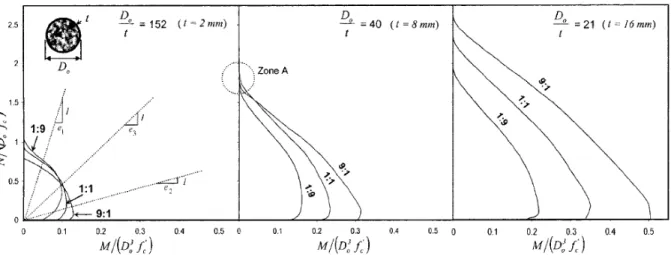
Figure 2.20: Normalized interaction diagram for concrete-filled FRP tubes of different thickness and laminate structures (Fam et al. 2003a) ... 30
Figure 2.21: Load-axial deformation relationships (Mohamed and Masmoudi 2008) ... 31
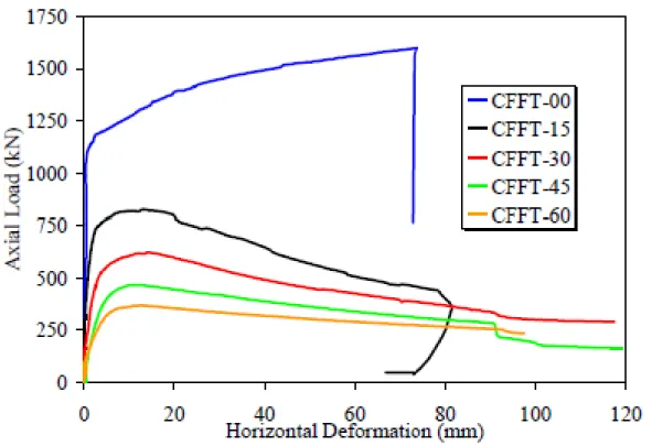
Figure 2.22: Load-horizontal deformation relationships (Mohamed and Masmoudi 2008) ... 32
Figure 2.23: Effect of loading FRP tube axially (Fam and Rizkalla 2001 a&b) ... 33
Figure 2.24: Effect of void size on confinement level (Fam and Rizkalla 2001a) ... 34
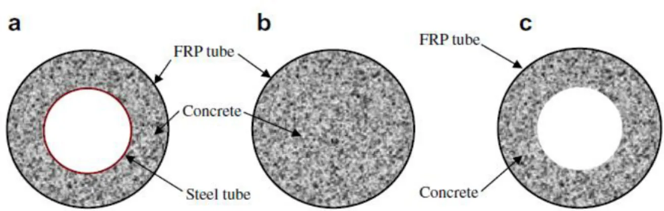
Figure 2.25: Cross-sections of (a) DSTCs, (b) FCSCs, and (c) FCHCs ... 36
Figure 2.26: Effect of stiffness of tube on confinement effectiveness (Fam and Rizkalla 2001a)……….37
Figure 2.27: Effect of slenderness and CFRP warpping scheme on peak load capacity (Fitzwilliam and Bisby 2010) ... 40
Figure 2.28: Biaxial stress-strain curves for bond effect specimens with multilayer shells (Mirmiran et al. 1998) ... 42
Figure 2.29: Normalized stress-strain curves of concrete-filled GFRP circular and square tubes (Mirmiran et al. 1998) ... 44
Figure 2.30: Influence of fiber orientation on axial stress-strain behaviour of CFFTs (Vincent and Ozbakkaloglu 2013b) ... 50
Figure 2.31: Variation of axial stress-fiber orientation strain relationships with fiber orientation (Vincent and Ozbakkaloglu 2013b) ... 51
Figure 2.32: Lam and Teng’s stress-strain model for FRP confined concrete (Lam and Teng 2003) ... 55
Figure 2.33: Equivalent circular cross section Lam and Teng (2003)... 56
Figure 2.34: Representative interaction diagram (ACI 440.2R-2008) ... 57
Figure 3.1: Compression test of the standard concrete cylinders ... 60
Figure 3.2: Splitting test of the standard concrete cylinders ... 61
Figure 3.4: Filament wound GFRP tubes ... 62
Figure 3.5: Test setup and load-strain curve for the FRP tubes for coupon tensile test (Masmoudi and Mohamed 2011 ) ... 63
Figure 3.6: Test setup and stress-hoop strain behaviour of the FRP tubes for split-disk test (Masmoudi and Mohamed 2011) ... 64
Figure 3.7: Typical details for the tested specimens and reinforcement layout: (a) CFFT columns; (b) control specimens ... 67
Figure 3.8: (a) FRP tubes; (b) and cardboard for columns (Mohamed 2010) ... 68
Figure 3.9: Reinforcement strain gauges instrumentations (Mohamed 2010) ... 69
Figure 3.10: Vertical and horizontal strain gauges ... 70
Figure 3.11: Horizontal LVDTs for measuring the lateral displacements ... 70
Figure 3.12: Vertical DTs for measuring the axial displacements ... 71
Figure 3.13: Column capping preparation ... 71
Figure 3.14: Top and bottom confined steel bolted plates ... 72
Figure 3.15: Schematic of the test setup and placing of specimen instrumentations ... 73
Figure 3.16: Test setup ... 74
Figure 3.17: Testing machine and a data acquisition system ... 75
Figure 4.1: Failure mode of specimen S-S(3.4)-C ... 77
Figure 4.2: Failure mode of specimen S-G(3.4)-C ... 78
Figure 4.3: Failure mode of specimen A-S(3.4)-C ... 78
Figure 4.4: Failure mode of specimen A-G(3.4)-C ... 79
Figure 4.5: Failure mode of specimen B-G(3.4)-C ... 79
Figure 4.6: Failure mode of specimen B-G(1.2)-C ... 80
Figure 4.7: Failure mode of specimen B-G(1.2)-M ... 80
Figure 4.8: Failure mode of specimen B-G(1.2)-C* ... 81
Figure 4.9: Overall failure modes of tested specimens ... 81
Figure 4.10: Axial cyclic stress-strain curves for control columns ... 83
Figure 4.11: Axial cyclic stress-strain curves for the reinforced-CFFT columns confined with tube type A... 84
Figure 4.12: Axial cyclic stress-strain curves for the reinforced-CFFT columns confined with tube type B ... 84
Figure 4.13: Typical axial cyclic stress-strain curves (Lam and Teng 2009) ... 86 Figure 4.14: Plastic strain versus envelop unloading strain relationships of test specimens .... 87 Figure 4.15: Stress deterioration ratio (β1) versus envelop unloading strain ... 88 Figure 4.16: Axial stress-strain relationships for longitudinal bars for the control columns .... 90 Figure 4.17: Axial stress-strain relationships for longitudinal bars for the reinforced-CFFT columns confined with tube type A ... 90 Figure 4.18: Axial stress-strain relationships for longitudinal bars for the reinforced-CFFT columns confined with tube type B ... 91 Figure 4.19: Strain distribution versus different strain gauges locations surrounding the column perimeter at the mid-height for specimen A-S(3.4)-C ... 92
Figure 4.20: Strain distribution versus different strain gauges locations surrounding the column perimeter at the mid-height for specimen A-G(3.4)-C ... 93
Figure 4.21: Strain distribution versus different strain gauges locations surrounding the column perimeter at the mid-height for specimen B-G(3.4)-C ... 94
Figure 4.22: Strain distribution versus different strain gauges locations surrounding the column perimeter at the mid-height for specimen B-G(1.2)-M ... 95
Figure 4.23: Experimental loads versus predicted values for the tested specimens (considering confinement codes limits) ... 101 Figure 4.24: Experimental loads versus predicted values for the tested specimens (with no considering confinement codes limits) ... 101
LIST OF SYMBOLS
SI units are used throughout the study presented herein. Unless otherwise stated, the symbols most frequently used have the following meanings:
Symbol Definition
Ac cross-sectional area of concrete in compression member;
Af area of FRP external reinforcement;
Ag gross area of concrete section;
As area of nonprestressed steel reinforcement;
Af area of nonprestressed FRP reinforcement;
D internal diameter of the FRP tubes;
Ec modulus of elasticity of concrete
Es steel elastic modulus;
Ef FRP elastic modulus;
E11 primary modulus of elasticity;
x
E tubes Young’s modulus in the axial direction; FRPU
E tubes Young’s modulus in the hoop direction; /
c
f unconfined cylinder compressive strength of concrete; /
cc
f confined concrete compressive strength; lFRP
f lateral confinement pressure of FRP;
lu
f ultimate lateral confinement stress;
a lu
f , actual lateral confinement stress; '
,a/ cc lu f
f actual confinement ratio;
FRPU
f tubes ultimate strength in the hoop direction;
x
f tubes ultimate strength in the axial direction;
fnew stress where the first reloading path reaches to the point corresponding to
the maximum axial strain in the envelop unloading path;
f t split cylinder tensile strength of concrete;
fu ultimate tensile strength of steel bars;
fy yield strength of steel bars;
ffu ultimate tensile strength of FRP bars;
G12 shear modulus;
Ka efficiency factor accounts for the geometry of the section, circular, and
noncircular;
kc factor accounts for the shape of the cross section, which is equal to 1.0 for
circular section and 0.4 for square and rectangular section; ke strength reduction factor applied for unexpected eccentricities;
Kε strain efficiency factor =0.55;
M Bending moment;
N axial compression force;
nf modular ratio of elasticity between FRP and concrete = Ef /Ec;
ns modular ratio of elasticity between steel and concrete = Es /Ec;
P11 resultant axial force;
Pm resultant forces in the matrix;
Pf resultant forces in the fibers;
Pu experimental ultimate load;
Pr factored axial load resistance of the confined columns; Qij denote the reduced stiffness of an orthotropic lamina;
tfrp FRP tubes thickness;
V volume fraction;
εco’ corresponding axial strain of unconfined concrete;
h, min minimum hoop strain for the tested specimen;
h, aver average hoop strain for the tested specimen;
h, max maximum hoop strain for the tested specimen;
FRPU
tubes ultimate tensile strain in the hoop direction;
x
tubes ultimate tensile strain in the axial direction;
εpl plastic strain (is defined as the residual axial strain when the stress
unloaded to zero stress of each unloading path);
εul,max maximum axial strain in the envelop unloading path;
ϕc material resistance factor for concrete;
ϕs material resistance factor for steel;
ϕFRP material resistance factor for FRP;
εun,env envelop unloading strains;
ρL longitudinal reinforcement ratio;
ρs Steel reinforcement ratio;
ρf FRP reinforcement ratio;
α1 multiplier on fc′ to determine intensity of an equivalent rectangular stress
distribution for concrete; β1 stress deterioration ratio;
νm poisson’s rations for the matrix;
νf poisson’s rations for the fibers;
CHAPTER 1
INTRODUCTION
1.1 Context and Problem Definition
Concrete-filled steel tubes (CFST) have been used as alternative to typical reinforced concrete (RC) columns, due to the full confinement effects for concrete and the construction efficiency of the tube as permanent formwork. The tube interacts with the core in three ways: i) it confines the core, thereby enhancing its compressive strength and ductility; ii) it provides additional shear strength for the core; and iii) depending on its bond strength with concrete and its stiffness in the axial direction, it develops some level of composite action, thereby also enhancing the flexural strength of concrete (Mirmiran and Shahawy 1997). Since steel is an isotropic material, its resistance in the axial and hoop directions cannot be uncoupled nor optimized. Steel high modulus of elasticity causes a large portion of axial loads to be carried by the tube, resulting in premature buckling. In addition, its Poisson's ratio is higher than that of concrete at early stages of loading. This differential expansion results in partial separation of the two materials, delaying the activation of confinement mechanism (Fam and Rizkalla, 2001). In cold regions or Canadian climates in an aging highway and marine infrastructure, steel tubes are exposed to harsh environment conditions such as significant temperature fluctuations, freeze-thaw cycles, marine sea spray, and chlorides accelerating the corrosion of steel tubes, which typically lead to significant deterioration and rehabilitation needs. These problems can be eliminated by using fiber-reinforced-polymer (FRP) tubes as an alternative to the steel tubes particularly where steel corrosion is a major concern.
The FRP tube provides lightweight structural component, permanent formwork, non-corrosive characteristics, protected the contained concrete from intrusion of moisture with corrosive agents that could otherwise deteriorate the concrete core and saving of construction time and effort. Furthermore, the laminate structure of FRP tubes could be optimized by controlling the proportions of fibers in the axial and hoop directions to suit the application
(Rizkalla and Fam, 2002). For instance the axial members, larger stiffness is required in the hoop direction as well as a minimum Poisson’s ratio in order to produce the maximum confinement of concrete. The composite system thus formed is commonly referred to as concrete-filled FRP tubes (CFFTs), and is found to be a viable alternative and has showed superior performance to RC or CFST for use as columns, piles, and beams. The promising concept of concrete-filled FRP tube (CFFT) system, that may be further reinforced with steel or FRP bars, has raised great interest amongst researchers in the last decade. The CFFT technique has been used successfully in different concrete structure elements such as pier column and girder for bridges and also as fender piles in marine structures (Fam et al 2003b).
Using FRP bars instead of conventional steel bars in the CFFT columns can provide a step forward to develop a promising totally corrosion-free new structural system. Nonetheless, investigation of the axial behaviour of FRP bars as longitudinal reinforcement in CFFT columns has been quite limited. To date, most of the experimental investigations performed on FRP confined concrete columns have considered short, unreinforced, small-scale concrete cylinders, tested under concentric, monotonic, and axial load (Mirmiran et al. 2001; Fam et al 2003a; Lam and Teng 2009; Ozbakkaloglu et al 2013; Vincent and Ozbakkaloglu 2014). The slenderness ratio and internal longitudinal reinforcement type (steel or FRP bars) effects on the behaviour of FRP confined concrete long columns have received only limited research attention. Thus, this experimental study is designed to investigate the axial behaviour of CFFT long columns reinforced with longitudinal steel and FRP bars under monotonic and axial cyclic compression loading.
1.2 Research Significance
This study, which presents experimental test results of circular CFFT long columns reinforced with steel or FRP bars, contributes to expand the knowledge in the area of CFFT, used as structural members, by addressing new parameters intended to simulate practical applications. Using FRP bars in the CFFT columns can provide a step forward to develop a totally corrosion-free new structural system. The effect of glass FRP (GFRP) tubes wall thicknesses, internal reinforcement type and amount, and nature of loading (monotonic and cyclic) on the strength and mode of failure of CFFT long columns is investigated.
1.3 Objectives
The main objectives of this research project can be summarized as follows:
1. Evaluate the axial behaviour of reinforced concrete and GFRP-CFFT long columns reinforced with steel and FRP bars.
2. Investigate the influencing of internal reinforcement type and amount, GFRP tubes thicknesses, axial monotonic and cyclic loading of the strength, strain capacity, and mode of failure of the tested columns.
3. Investigate the influencing of the investigated parameters on the shape of unloading/reloading paths, the ultimate axial strain, and plastic strain values of steel and FRP-reinforced CFFT columns.
4. Evaluate the accuracy of the existing design equations as provided in ACI and CSA codes and design guidelines to predicate the axial compression capacity of the test specimens.
1.4 Methodology
In order to achieve these objectives, an experimental program is designed. The experimental program focuses on axial behaviour of RC and CFFT circular columns internally reinforced with steel and FRP bars. The test specimens included construction and testing of ten fixed-fixed columns measuring 1900 mm in-height and 203 mm-in diameter. The test specimens were divided into two series denoted as Series I and II. Series I included three control RC specimens reinforced with a longitudinal reinforcement ratio (ρL) equals to (3.4%),
one specimen reinforced with steel bars and two identical specimens reinforced with GFRP bars. Steel spiral stirrups (pitch = 50.6 mm) were used as transverse reinforcement to have approximately similar hoop stiffness of the GFRP tube (Type A). Series II consisted of seven reinforced CFFT columns laterally confined with GFRP tubes (Type A or B). One specimen reinforced steel bars and laterally confined with tube type (A). Four specimens reinforced with GFRP bars (ρL = 1.2 and 3.4%) and laterally confined with tubes type (A and B). In addition,
two identical specimens reinforced with CFRP bars (ρL = 1.2 %) and laterally confined with
tube type (A). All specimens were tested under single complete unloading/reloading cyclic axial compression loading, except for one specimen, which was tested under monotonic axial
compression loading. The investigated test parameters were: (i) GFRP tubes thicknesses (2.9 and 6.4 mm); (ii) internal reinforcement type (steel; GFRP; or CFRP bars) and amount; and (iii) nature of loading (i.e. monotonic and cyclic).
1.5 Organization of the Dissertation
This dissertation consists of five chapters. The following is a brief description of each:
Chapter 1: This chapter defines the problem and summarizes the main objectives and
originality of the research program. The methodology undertaken to achieve these objectives is also emphasized.
Chapter 2: This chapter provides general information on the FRP composites materials and
their characteristics. The chapter also presents background and review on modeling FRP tubes and test methods to evaluate the mechanical properties of FRP tubes. An overview of the background literature carried out to investigate the structural behaviour of CFFT column with different parameters is reviewed. Furthermore, design guide (recently published in Canada and USA) of the concrete infill columns structures are also covered.
Chapter 3: This chapter describes the experimental program conducted at the University of
Sherbrooke to test 10 RC and CFFT columns internally reinforced with (steel and FRP bars). In this chapter, the details of test specimens, test setup, and instrumentation are given. The chapter provides detailed characteristics of the materials used in the research program.
Chapter 4: This chapter presents the results obtained from the experimental investigation. The
influence of each test parameter on the axial behaviour of the tested columns is also discussed. The behaviour of the tested columns in each series is discussed in terms of failure mode, axial and lateral stress strain responses, the plastic strains and stress deterioration. Furthermore, the effect of the GFRP tube thickness on confinements, internal longitudinal reinforcement steel or FRP bar and loading pattern (monotonic and cyclic) are discussed as well. The accuracy of the existing design equations as provided in ACI and CSA codes and design guidelines to predicate the axial compression capacity of the test specimens is also highlighted.
Chapter 5: A summary of this investigation is given in this chapter. The chapter also presents
CHAPTER 2
LITERATURE REVIEW
2.1 General
Harsh environmental effects, such as significant temperature fluctuations, freeze-thaw cycles, and high concentrations of chlorides, on concrete bridge pier columns and piles have resulted in their steady deterioration that shortens their long-term durability and structural integrity. The key problems are permeability of concrete and corrosion of the embedded steel reinforcement. One promising innovative structural system is concrete filled fiber-reinforced polymer (FRP) tubes, which provide many unique advantages (Seible 1996). The FRP tube acts as a stay-in-place structural formwork to contain the fresh concrete, which may save the costs of formwork and labor used by the cast-in-place or precast industries. At the same time, the FRP tube acts as non-corrosive reinforcement for the concrete for flexure and shear. More importantly, the FRP tube provides confinement to the concrete in compression, which significantly improves the strength and ductility. The contained concrete is protected from severe environmental effects and deterioration resulting from moisture intrusion (Mirmiran 1995).
This chapter provides brief information on the FRP materials and their characteristics compared to steel reinforcement, modeling FRP tubes and test methods to evaluate the mechanical properties of FRP tubes. An overview of the background literature carried out to investigate the structural behaviour of CFFT column with different parameters is reviewed. Furthermore, codes design guides (recently published in Canada and USA) of the concrete infill columns structures are also examined.
2.2 FRP Composite Materials
“FRP” is an acronym for fiber-reinforced polymers. The term composite material is a generic term used to describe combination of two or more materials, which yield a product that is more efficient from its strength. The fibers provide the tensile strength, which are
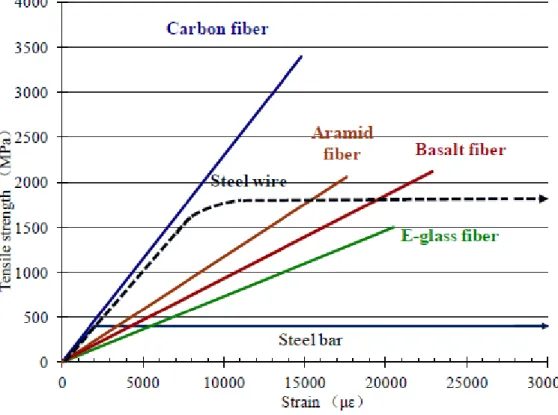
embedded in the matrix. The matrix provides protection and support for the sensitive fibers as well as local stress transfer from one fiber to another. The matrix, such as a cured resin-like epoxy, polyester, vinyl ester, or other matrix acts as a binder and holds the fibers in the intended position, giving the composite material its structural integrity by providing shear transfer capability. Three FRPs are commonly used (among others): composites containing glass fibers are called glass fiber reinforced polymers (GFRP); those containing carbon fibers are called carbon fiber reinforced polymers (CFRP); and those reinforced with aramid fibers are referred to as aramid fiber reinforced polymers (AFRP). GFRPs are the most inexpensive compared to the other commercially available FRPs, consequently the most commonly used fibers in structural engineering applications. Moreover, the latest FRP composite is namely Basalt FRP (BFRP), which has developed within the last ten years and has higher tensile strength than E-glass fibers but lower than S-glass; however, its cost is near the cost of E-glass (Zhishen et al., 2012).
Figure 2.1: Typical stress-strain relationships of different FRPs compared to steel bars (Zhishen et al., 2012)
Typical stress-strain relationships of different FRPs compared to steel bars relationship are shown in Figure 2.1. FRP is linear elastic up to final brittle rupture when subject to tension while steel shows an elastic-plastic region. These curves give a clear contrast between the brittle behaviour of FRP composite and the ductile behaviour of steel. The fundamental difference between steel and FRP materials is due to the stress-strain behaviour of steel, which after the initial linearly elastic phase displays the yielding plateau. Therefore, after reaching the maximum value corresponding to the yielding stress the confinement pressure remains constant (neglecting strain hardening).
2.3 Modeling of FRP Tubes
Mechanical properties of FRP materials depend on the fabrication technique, type and properties of its components, particularly the fibers, and the volume fraction of the fibers in the overall mix. Pressure or vacuum molding generally results in a higher fiber volume fraction as compared to hand lay-up. While the ultimate strength of FRP materials depends on the strength and modulus of the fibers, its in-service properties are functions of the matrix. Fibers generally exhibit linear elastic behaviour, while resins are visco-elastic or visco-plastic. As such, linear elastic behaviour of fibers is generally the dominant factor in the response of unidirectional FRP materials loaded in the direction of the fibers. However, a nonlinear behaviour is often observed in the off-axis direction, under certain fiber orientations and fiber volume ratios, as the matrix resists the pull out of broken fibers in shear.
FRP materials are laminate structures made up of a stack of lamina with various fiber orientations. Bonding of the plies or layers of a laminate is often made with the same matrix used in the lamina. In the filament-winding of a tube, for example, each fiber orientation represents a ply, and the entire laminate is made with the same matrix in a single batch. Figure 2.2 shows the different modes of failure in laminate structures, including fiber rupture, transverse or longitudinal cracking of the matrix, debonding at the fiber-matrix interface, and delamination between different layers.
Figure 2.2: Modes of failure in a laminate (Berthlot 1995)
Because of their inherent heterogeneous and anisotropic nature, FRP materials are studied from two points of view: micromechanics and macro-mechanics. The former is a study of FRP at the level of its constituent materials and their interaction at a microscopic scale, whereas the latter is a study of FRP materials at a macroscopic scale, assuming homogeneity along with the average properties of the constituent materials. On the other hand, FRP materials are more advantageous than their isotropic counterparts, because they can be engineered or tailored for optimum properties in different directions. The tailoring process includes selecting appropriate constituents, fiber volume fraction, fiber orientation, and the stacking sequence of layers.
Figure 2.3 shows fibers uniformly dispersed within a matrix in a unidirectional lamina. Perfect bond is assumed at the interface between fibers and the matrix. The lamina, therefore, has orthotropic properties with the greatest stiffness and strength in the direction of fibers. The primary modulus of elasticity E11 can be calculated as
where E and V are the elastic modulus and volume fraction, respectively, and subscripts f and
m denote fibers and the matrix, respectively. The above equation, known as the “law of
mixture,” can be derived from the resultant axial force P11 in the lamina, as given by
P11PmPf (2.2)
where Pm and Pf are the resultant forces in the matrix and the fibers, respectively. The equation
can be written in terms of stresses as
11A11mAmfAf (2.3)
where σ and A are the stress and area identified with subscripts for each phase, and therefore, in terms of volume fractions, it can be written as
11mVmfVf (2.4)
from which, one can derive Equation (2.1), assuming strain compatibility. Similarly, the Poisson's ratio ν12 of the lamina can also be written as
v12 mVmfVf (2.5)
where νm and νf are the Poisson’s rations for the matrix and the fibers, respectively. The
transverse modulus of elasticity E22 can be written as
E22 EfEm/
EmVf EfVm
(2.6)Finally, the shear modulus G12 is expressed as
G22 GfGm/
GmVf GfVm
(2.7)At the macromechanics level, the stress-strain relationship of uni-directional lamina can be sufficiently described using the generalized Hooke's law, as
12 31 23 3 2 1 66 55 44 33 23 13 23 22 12 13 12 11 12 31 23 3 2 1 0 0 0 0 0 0 0 0 0 0 0 0 0 0 0 0 0 0 0 0 0 0 0 0 C C C C C C C C C C C C (2.8)
where σi (i = 1, 2, 3) and εi (i = 1, 2, 3) are the normal stresses and strains in the three principal
material directions (see Figure 2.3), respectively, and τij (i,j = 1, 2, 3) and γij (i,j = 1, 2, 3) are
the shear stresses and strains, respectively, and Cij are stiffness coefficients. For a thin
orthotropic shell, transverse strains are negligible, and therefore, it can be shown that
0 0 0 0 0 0 3 3 23 23 13 13 (2.9)
As such, the constitutive equations can be simplified in the principal material directions of the orthotropic material as
12 2 1 66 22 12 12 11 3 2 1 0 0 0 0 Q Q Q Q Q (2.10)
where Qij denote the reduced stiffness of an orthotropic lamina, and are related to the
engineering properties measured along the principal directions, as given by
66 12 21 12 2 11 21 12 2 12 12 21 12 1 11 1 vE v ;Q 1vvEv ;Q 1 Ev v ;Q G Q (2.11)
The above relations were developed for the principal materials directions in an orthotropic material. However, the principal directions of orthotropy often do not coincide with the geometric coordinate system, as evident in a helically wound glass FRP tube (see Figure 2.4). Transformation from the principal materials direction to an arbitrary coordinate system can easily be done, as shown in Figure 2.5, using the following equation:
12 2 1 2 2 2 2 2 2 sin cos cos . sin cos . sin cos . sin 2 cos sin cos . sin 2 sin cos x x (2.12) where φ is the angle of rotation. Similar transformations can be applied to the strains and material properties of the shell.
Figure 2.3: Macromechanics of FRP composites (Hollaway 1990)
As stated earlier, nonlinearity in the off-axis direction could be significant. Hahn and Tsai (1973) used a complementary energy density function to derive nonlinear relations for in-plane shear. Hahn (1973) extended the nonlinear theory of unidirectional lamina to that of laminated composites. Lifshitz (1998) studied the shear modulus of T300-934 graphite/epoxy lamina with four layers at fiber orientations of ±45º. Hu (1993) reported that unidirectional FRP may exhibit severe nonlinearity in its in-plane shear stress-strain relation. Also, some deviation from linearity may be observed under in-plane transverse loading, but the degree of nonlinearity is not comparable to that of the in-plane shear.
Figure 2.4: Helically wound fiber reinforced cylindrical shell (Jones 1975)
Haj-Ali and Kilic (2002) made coupon tests to calibrate three-dimensional micromechanical models for E-glass/vinyl-ester pultruded FRP. Tension, compression, and shear tests were performed on off-axis coupons cut at different angles of 0°, 15°, 30°, 45°, 60°, and 90°. The overall linear elastic properties were identified along with the nonlinear stress-strain behaviour under in-plane multi-axial tension and compression loading. The material had a lower ultimate tensile stress and initial stiffness in tension compared to the corresponding values from compression tests, regardless of thickness and orientation. This was attributed to the existing voids and micro-cracks that are more pronounced in matrix mode tensile loading. The difference between the compressive and tensile properties increased for off-axis angles approaching 90°.
2.3.1 Test Methods
The classical lamination theory provides a feasible method to evaluate the mechanical properties of FRP tubes. This theory, however, involves complicated calculations for FRP laminates, practically those with asymmetric unbalanced laminate structures. In addition, non-linear behaviour may be dominated for FRP tubes with angle-ply laminate structures, which cannot be predicted by lamination theory. Moreover, some previous research (e.g. Fam 2000) showed that the error of predications of the lamination theory may be up to 40% for the ultimate strength up to 25% for the elastic modulus and up to 50% for Poisson’s ratio. Thus, standard tests are important for more accurate evaluation of the mechanical properties of FRP tubes.
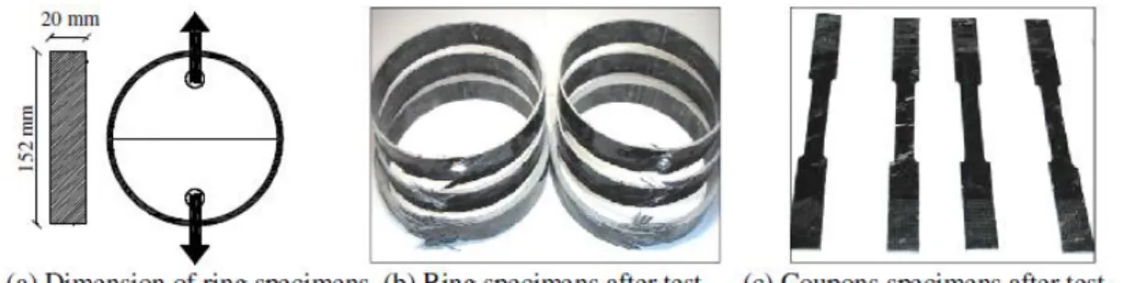
The most popular test standards for tensile properties of FRP appear to be ASTM D638– 10 (2010) and ASTM D2290–12 (2012) which provide test methods for the determination of the tensile properties for FRP tubes using a flat coupon test and split disk test, respectively. On the other hand, the most popular test standard for the compressive properties of FRP includes ASTM D3410/D3410M-08 (2008) which provides a test method for the compressive properties of FRP through shear loading tests. Typical test samples of this standard are shown in Figure 2.6. Figure 2.7 presents the axial tensile stress-strain responses resulted from the coupon tests and Figure 2.8 shows the average stress-strain relationships for the split-disk test in the hoop direction. Lam and Teng (2004) concluded that the ultimate strength obtained by the ring-splitting test is in general lower than that obtained from the corresponding flat coupon test, mainly due to the effect of curvature. Despite the difference in the ultimate strength, Lam and Teng (2004) also found that the elastic modules obtained from these two test methods are almost the same.
Figure 2.6: Specimens of FRP tubes for the split-disk test and coupon tensile test (Masmoudi and Mohamed 2011)
Figure 2.7: Test setup and load-strain curve for the FRP tubes for coupon tensile test (Masmoudi and Mohamed 2011)
Figure 2.8: Test setup and stress-hoop strain behaviour of the FRP tubes for split-disk test
(Masmoudi and Mohamed 2011)
2.4 Confinement of Concrete
Concrete is one of the most commonly analyzed structural civil engineering materials in use today. The difficulty in characterizing the mechanical behaviour of concrete is due to its highly nonhomogeneous structure. In addition, the interaction between the cement paste and
aggregate causes the nonlinearity of the concrete stress-stain response. At relatively low stress levels, the development and propagation of micro-cracks at the aggregate-paste interfaces soften the concrete, resulting in a somewhat parabolic stress-strain curve (Collins and Mitchell 1997). It was demonstrated that with the increase in concrete strength, the ductility decreases, whereas initial stiffness and linearity of the curve increase (see Figure 2.9). Once the maximum stress (f’c) is reached at a strain εo, concrete cannot support this high level of stress
with increasing deformation. For concrete strengths less than about 41MPa, the stress-strain relationship can be reasonably described by a simple parabola (Collins and Mitchell 1997).
Figure 2.9: Typical compressive stress-strain curves (Collins and Mitchell 1997) The basic principle of confinement, which adds another dimension to columns analysis, consists of imposing a restriction on the lateral expansion of the concrete, and its corresponding crack growth, due to axial stress. When properly confined, the concrete can sustain plastic deformation with axial strains and stresses higher than its unconfined failure values (Considere 1903; Richart et al. 1928; Mirmiran et al. 1998; Saafi et al. 1999; Fam and Rizkalla 2001; Hong and Kim 2004; Fam et al. 2005; Ozbakkaloglu and Oehlers 2008 a, b; Mohamed and Masmoudi 2010; Park et al. 2011; and Ozbakkaloglu 2013a, b, c, etc.). Figure
2.10 shows the effect of hydraulic confining pressure on stress-strain response. Confinement considerably increases the energy absorption capacity of concrete. Thus, in seismic regions, appropriately detailed transverse reinforcement and/or wrapped with FRP or encasing concrete in tubes (steel or FRP) is provided to confine the concrete and hence increase the ductility of columns and beams (Kent and Park 1971; Sheikh 1978; Sheikh and Uzumeri 1980; Seible et al. 1996; Yamakawa et al. 2003; Zhu et al. 2006; Ozbakkaloglu and Saatcioglu 2006, 2007; Saatcioglu et al. 2008; and Idris and Ozbakkaloglu 2013).
Figure 2.10: Effect of lateral pressure on stress-strain response (Richart et al. 1928)
2.5 Confinement Mechanism
2.5.1 Confinement by lateral steel reinforcement
In practice, columns are confined by lateral reinforcement, commonly in the form of closely spaced steel spirals or hoops. At low levels of stress in the concrete, the lateral reinforcement is hardly stressed, thus the concrete exhibits unconfined behaviour. When stresses approach the uniaxial strength, the progressive internal cracking cause high lateral
strains. The concrete bears out against the lateral reinforcement, which then apply a confining reaction to the concrete and hence the concrete exhibits a confined behaviour (Park and Paulay 1975). Confinement of different column shapes is presented in the following:
(a) Circular columns: Circular spirals, because of their shape, are in axial hoop tension and
provide continuous confining pressure around the circumference. The pressure provided by closely spaced circular spirals and vertical column reinforcement can be considered to be uniform around the perimeter of the core (Saatcioglu and Razvi 1992). Figure 2.11 shows the lateral pressure of circular column.
Figure 2.11: Lateral pressure in circular columns: (a) uniform buildup of pressure; and (b) computation of lateral pressure from hoop tension (Saatcioglu and Razvi 1992)
(b) Square columns: Square and rectangular hoops can apply confining pressure only at the
corners of the ties, thus causing a portion of the core concrete to remain unconfined (See Figure 2.12). Passive confinement pressure exerted by a square hoop is dependent on the restraining force developed in the hoop steel. The hoop steel can develop high restraining forces at the corners, where it is supported laterally by transverse legs, and low restraining action between the laterally supported corners. The restraining force at the corners depends on the force that can be developed in the transverse legs, which, in turn, is related to the area and strength of the hoop steel. The restraining action of the hoop, between the corners is related to the flexural rigidity of the hoop steel, which depends on the size and unsupported length of the bar. This restraining action is proportional to the elastic rigidity of the hoop steel until
yielding. Beyond yielding, the restraining action remains approximately constant until the strain hardening of steel produces additional restraining action. However, the flexural rigidity of the hoop between the laterally supported nodal points and the resulting restraining action is very small as compared to the restraining action of the corners and the other nodal points. Therefore, as the concrete expands laterally under axial compression, there will be higher reactive pressures building up at the nodal points than at locations away from the nodes. Figure 2.13 (a) illustrates the buildup of passive confinement pressure in a square column. If cross ties or inside hoops are used to support the middle bars, additional points of high lateral restraint are generated. It is clear that the shape of the pressure distribution is a function of the reinforcement arrangement. Shapes of pressure distributions for various tie arrangements are shown in Figure 2.13 (b).
Figure 2.13: Lateral pressure in square columns: (a) Lateral pressure buildup in square columns; and (b) pressure distributions resulting from different reinforcement arrangements
(Saatcioglu and Razvi 1992)
(c) Rectangular columns: Rectangular columns may have different confinement
reinforcement in two orthogonal directions. This may lead to different levels of confinement pressure along the long and short sides of the section. Figure 2.14 illustrates lateral pressure distributions along the long and short sides of a rectangular-column section. Confinement pressure along the long side plays a more dominant role on concrete strength than that along the short side. Examination of experimental data indicates that the effects of confinement pressures along the long and short sides can be considered to be proportional to the cross sectional dimensions.
Figure 2.14: Lateral pressure in distribution in rectangular columns (Saatcioglu and Razvi 1992)
2.5.2 Confinement by steel tubes
Another form of concrete confinement is by encasing concrete in a steel tube (Kloppel and Goder 1957). The steel tube acts as longitudinal, transversal, and shear reinforcement; formwork; and as a continuous confining jacket, which provides a tri-axial state of stress for concrete under compression. In return, concrete delays local buckling of the tube (Gardner and Jacobson 1967). Moreover, circular sections provide uniform flexural strength and stiffness in all directions. Due to the large shear capacity of concrete-filled steel tubular members, they predominantly fail in flexure in a ductile manner (Fam 2000).
It should be noted, however, that in addition to the corrosion problems of steel tubes, the confinement effectiveness is reduced at low levels of loading if the tube is also loaded in the axial direction. This is attributed to the fact that Poisson’s ratio of concrete at low levels of loading, 0.15 to 0.2, is smaller than the 0.3 value of steel, which rather tends to separate (Prion and Boehme 1994; Wei, Mau, and Mantrala 1995). As loading increases, lateral expansion of unconfined concrete approaches that of steel as micro cracking of the concrete increases and Poisson's ratio reaches up to 0.6. Consequently, a radial pressure develops at the steel-concrete
Normally, after the unconfined cylinder strength is attained, concrete would tend to spall and disintegrate in the absence of the confining jacket. However, if the jacket buckles before strains are large enough to develop the unconfined cylinder strength; the full strength of concrete cannot be utilized. It was reported that concrete begins to increase in volume at a strain level of about 0.002 (Knowles and Park 1969) and confinement is activated at stress level of 95 percent of the concrete strength (Prion and Boehme 1994). At this stage, the concrete is stressed tri-axially and the tube bi-axially. The interaction between the tube and the core results in a synergistic effect where the capacity of the composite column exceeds the sum of the individual strengths of steel and concrete (Kilpatrick and Rangan 1997). Prion and Boehme (1994) reported that the confining level is higher if the axial load is applied to the concrete only as the steel shell will not expand laterally and keep in contact with concrete. However, in practice, bond stresses and friction cause longitudinal strain in steel, which also reduces the yield strength in both directions.
2.5.3 Confinement by FRP tubes
Concrete filled FRP tubes (CFFTs) are a simple system comprised of filling prefabricated hollow FRP tubes with concrete. The FRP tubes are fabricated in a number of different ways, which include pultrusion, filament winding, spin casting or hand lay-up. The layers of fibre may also be oriented in a number of different directions, including longitudinal, circumferential or at angles, depending on the desired structural requirements. These CFFTs may or may not be further strengthened with the addition of conventional internal reinforcing steel bars and/or prestressing steel strands. CFFTs are particularly advantageous because the prefabricated hollow FRP tube serves as stay-in-place formwork, which greatly simplifies construction. In addition, these FRP tubes provide confinement for the inner concrete core, which not only increases its compressive strength, but also protects the core from the aggressive environmental conditions.
FRP jackets, other than being much lighter than steel jackets and non-corrosive, provide other advantages from the structural point of view. FRP-confined concrete is insensitive to small lateral expansion due to its lower Young’s modulus which forces concrete to carry most of the axial load, therefore, allowing the shell to be more solicitude in the hoop direction rather than failing prematurely by outward local buckling in the axial direction (Rizkalla and Fam
2002). As the unconfined strength is approached, high lateral expansion occurs due to major microcracking, which activates the FRP jacket. Passive confining pressure, continuously increasing due to the linear characteristics of the FRP, is induced. Once the jacket reaches its hoop strength, it ruptures, and the concrete fails. Unlike steel jackets, the FRP expansion in the hoop direction due to axial load is less than that of concrete at the early stage of loading for most laminates. This results in eliminating any separation of the FRP tube with the concrete or delay of the confinement process. In addition, the orthotropic laminate structure of FRP shells allows uncoupling of the two fiber orientations for design optimization as reported by Shahawy and Mirmiran (1998).
The fundamental difference between FRP and steel tubes is that the stress-strain behaviour of steel, which after the initial linearly elastic phase, displays the yielding plateau. Therefore, after reaching the maximum value corresponding to the yielding stress, the confinement pressure remains constant (neglecting strain hardening). Another difference is the greater stiffness of steel when compared to FRP (especially to GFRP, whereas CFRP may reach even higher values of elastic modulus). Both differences are reflected in the typical axial stress-strain behaviour of steel-confined and FRP-confined concrete, illustrated in Figure 2.15. Stresses and strains are normalized with respect to the unconfined concrete strength and peak strain. The steel-confined concrete follows an approximately linear trend before reaching the peak stress ( f’cc) after which it follows a gradual post-peak descending branch, therefore, the
ultimate stress ( fcu) is lower than the peak stress.
The FRP confined concrete displays a distinct bilinear response with a sharp softening and a transition zone at the level of its unconfined strength (f’co), after which the tangent
stiffness stabilizes at a constant value until reaching the ultimate strength. Thus, the peak point coincides with the ultimate point and they both correspond to tensile rupture of the FRP confining device. It has been noted that the strain measured in the confining FRP at rupture is in most cases lower than the ultimate strain of the FRP tested in uniaxial tension (see, for example, Matthys et al. 1999; Lorenzis and Tepfers 2003). The ever-increasing response is associated to the absence of yielding. The decrease in stiffness at the level of the concrete unconfined strength is due to the lower stiffness of the FRP confining device with respect to steel (in Figure 2.15 it can be seen that it is more pronounced for GFRP than for CFRP
confinement, the latter being very close to the response of the steel-confined column). From the observed behaviour, it has been noted that the value of the confined strength is essentially dependent on the maximum confining pressure that the FRP may apply, whereas the slope of the second branch of the stress-strain relationship (and, as a consequence, the value of the strain at peak stress) is mainly related to the confinement stiffness.
Figure 2.15: Axial stress-strain behaviour of confined concrete (Spoelstra and Monti 1999) Samaan et al. (1998) attributed the difference in behaviour between steel-confined concrete and FRP-confined concrete to the distinctly different dilation behaviour of concrete as shown in Figure 2.16. The dilation response of FRP-confined concrete is initially similar to unconfined concrete. It reaches a peak value, after which it decreases and finally stabilizes. Steel jackets effectively confine the concrete and control dilation before yielding. After yielding of the confining steel, the lateral confining pressure from steel confinement becomes essentially constant, thus allowing for increasing lateral dilation of confined concrete with increasing axial strains.
Figure 2.16: Dilation curves of GFRP-confined concrete versus steel-confined concrete (Samaan et al 1998)
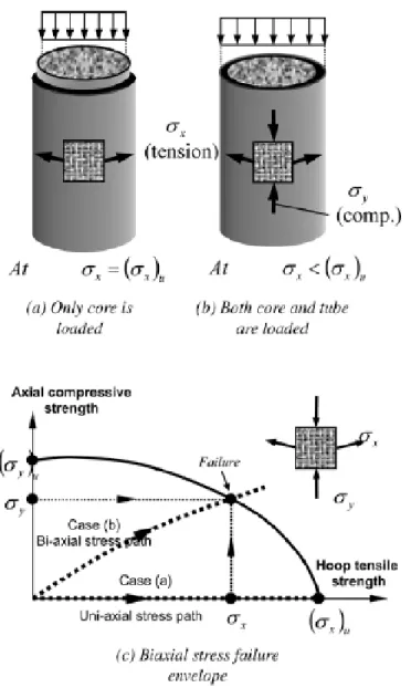
Fam and Rizkalla (2001b) reported the following equation that summarizes the critical parameters affecting the confinement pressure σR in circular CFFT, which directly contributes
to the enhanced axial strength of the concrete.
c1 R cc c f c R E t E (2.13)
At any axial strain level εcc, σR is increased as the stiffness of the tube in the hoop direction (Ef
t/R) is increased, where Ef is the equivalent orthotropic elastic modulus of the tube in the hoop
direction, t is the thickness of the tube, and R is the radius. The confinement pressure σR also
increases as the dilation of concrete increases as reflected by its Poisson’s ratio νc. Ec is the
modulus of the concrete core. Equation (2.13) represents an FRP tube fully utilized in the circumferential direction (debonded from concrete and not loaded axially), as shown in Figure 2.23.