Faculté de Génie
Département de Génie Civil
GFRP- REINFORCED CONCRETE COLUMNS UNDER
SIMULATED SEISMIC LOADING
COLONNES EN BÉTON ARMÉ RENFORCÉES DE PRFV SOUS UN
CHARGEMENT SISMIQUE SIMULÉ
Thèse de doctorat
Spécialité: génie civil
Mohammed Gaber Elshamandy Mohammed
A dissertation submitted in partial fulfillment
of the requirements for the degree of
Doctor of Philosophy
(Civil Engineering)
Jury: Prof. Brahim Benmokrane (Directeur de recherche)
Prof. Murat Saatcioglu (Examinateur)
Prof. Amr ElRagaby (Examinateur)
Prof. Sébastien Langlois (Examinateur et rapporteur)
Sherbrooke (Québec) Canada
March 2017
UNIVERSITÉ DE
i
ABSTRACT
Steel and fiber-reinforced-polymer (FRP) materials have different mechanical and physical characteristics. High corrosion resistance, high strength to weight ratio, non-conductivity, favorable fatigue enable the FRP to be considered as alternative reinforcement for structures in harsh environment. Meanwhile, FRP bars have low modulus of elasticity and linear-elastic stress-strain curve. These features raise concerns about the applicability of using such materials as reinforcement for structures prone to earthquakes. The main demand for the structural members in structures subjected to seismic loads is dissipating energy without strength loss which is known as ductility. In the rigid frames, columns are expected to be the primary elements of energy dissipation in structures subjected to seismic loads.
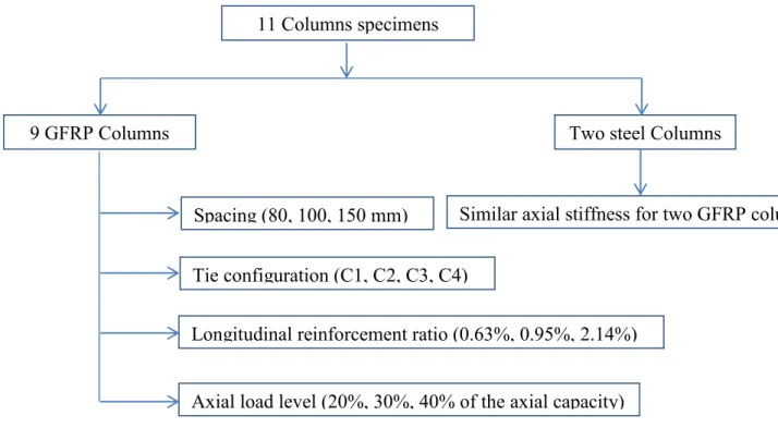
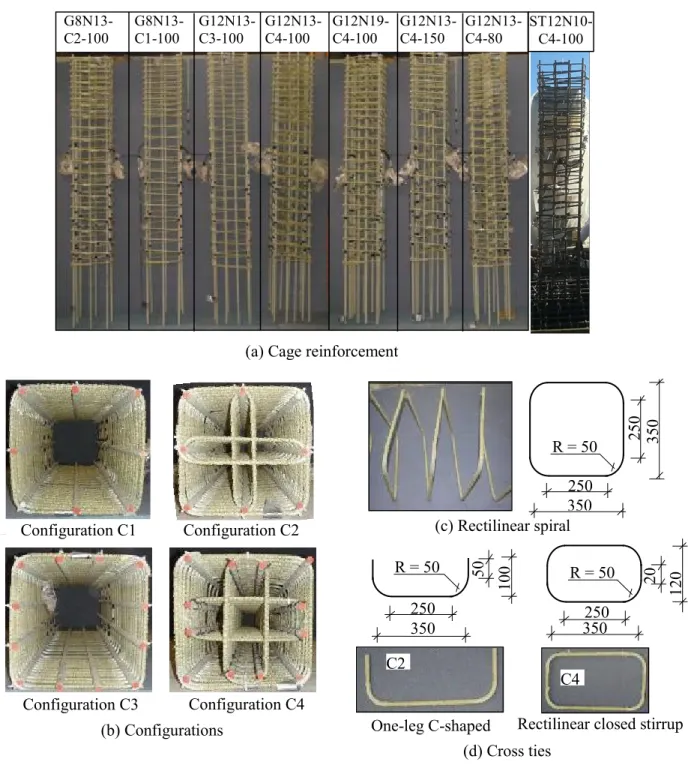
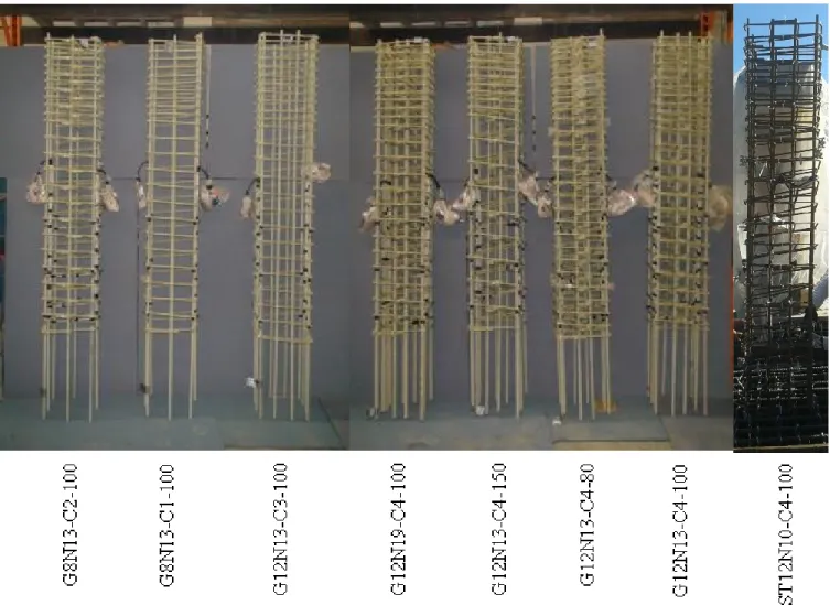
The present study addresses the feasibility of reinforced-concrete columns totally reinforced with glass-fiber-reinforced-polymer (GFRP) bars achieving reasonable strength and the drift requirements specified in various codes. Eleven full-scale reinforced concrete columns—two reinforced with steel bars (as reference specimens) and nine totally reinforced with GFRP bars—were constructed and tested to failure. The columns were tested under quasi-static reversed cyclic lateral loading and simultaneously subjected to compression axial load. The columns are 400 mm square cross-section with a shear span 1650 mm. The specimen simulates a column with 3.7 m in height in a typical building with the point of contra-flexure located at the column mid-height. The tested parameters were the longitudinal reinforcement ratio (0.63, 0.95 and 2.14), the spacing of the transverse stirrups (80, 100, 150), tie configuration (C1, C2, C3 and C4), and axial load level (20%, 30% and 40%).
The test results clearly show that properly designed and detailed GFRP-reinforced concrete columns could reach high deformation levels with no strength degradation. An acceptable level of energy dissipation compared with steel-reinforced concrete columns is provided by GFRP reinforced concrete columns. The dissipated energy of GFRP reinforced concrete columns was 75% and 70% of the counter steel columns at 2.5% and 4% drift ratio respectively. High drift capacity achieved by the columns up to 10% with no significant loss in strength. The high drift capacity and acceptable dissipated energy enable the GFRP columns to be part of the moment resisting frames in regions prone to seismic activities. The experimental
ABSTRACT
ii
ultimate drift ratios were compared with the estimated drift ratios using the confinement Equation in CSA S806-12. It was found from the comparison that the confinement Equation underestimates values of the drift ratios thus the experimental drift ratios were used to modify transverse FRP reinforcement area in CSA S806-12. The hysteretic behavior encouraged to propose a design procedure for the columns to be part of the moderate ductile and ductile moment resisting frames. The development of design guidelines, however, depends on determining the elastic and inelastic deformations and on assessing the force modification factor and equivalent plastic-hinge length for GFRP-reinforced concrete columns. The experimental results of the GFRP-reinforced columns were used to justify the design guideline, proving the accuracy of the proposed design equations.
Keywords: Concrete columns, GFRP bars, hysteretic response, ductility parameters, energy dissipation, drift capacity, displacement-based design
iii
RÉSUMÉ
L‘acier et les matériaux à base de polymères renforcés de fibres (PRF) ont des caractéristiques physiques et mécaniques différentes. La résistance à la haute corrosion, le rapport résistance vs poids, la non-conductivité et la bonne résistance à la fatigue font des barres d‘armature en PRF, un renforcement alternatif aux barres d‘armature en acier, pour des structures dans des environnements agressifs. Cependant, les barres d‘armature en PRF ont un bas module d‘élasticité et une courbe contrainte-déformation sous forme linéaire. Ces caractéristiques soulèvent des problèmes d'applicabilité quant à l‘utilisation de tels matériaux comme renforcement pour des structures situées en forte zone sismique. La principale exigence pour les éléments structuraux des structures soumises à des charges sismiques est la dissipation d'énergie sans perte de résistance connue sous le nom de ductilité. Dans les structures rigides de type cadre, on s'attend à ce que les colonnes soient les premiers éléments à dissiper l'énergie dans les structures soumises à ces charges.
La présente étude traite de la faisabilité des colonnes en béton armé entièrement renforcées de barres d‘armature en polymères renforcés de fibres de verre (PRFV), obtenant une résistance et un déplacement latéral raisonnable par rapport aux exigences spécifiées dans divers codes. Onze colonnes à grande échelle ont été fabriquées: deux colonnes renforcées de barres d'acier (comme spécimens de référence) et neuf colonnes renforcées entièrement de barres en PRFV. Les colonnes ont été testées jusqu‘à la rupture sous une charge quasi-statique latérale cyclique inversée et soumises simultanément à une charge axiale de compression. Les colonnes ont une section carrée de 400 mm avec une portée de cisaillement de 1650 mm pour simuler une colonne de 3,7 m de hauteur dans un bâtiment typique avec le point d‘inflexion situé à la mi-hauteur. Les paramètres testés sont : le taux d‘armature longitudinal (0,63%, 0,95% et 2,14 %), l'espacement des étriers (80mm, 100mm, 150 mm), les différentes configurations (C1, C2, C3 et C4) et le niveau de charge axiale (20%, 30 % et 40%).
Les résultats des essais montrent clairement que les colonnes en béton renforcées de PRFV et bien conçues peuvent atteindre des niveaux de déformation élevés sans réduction de résistance. Un niveau acceptable de dissipation d'énergie, par rapport aux colonnes en béton armé avec de l‘armature en acier, est atteint par les colonnes en béton armé de PRFV.
RÉSUMÉ
iv
L'énergie dissipée des colonnes en béton armé de PRFV était respectivement de 75% et 70% des colonnes en acier à un rapport déplacement latéral de 2,5% et 4%. Un déplacement supérieur a été atteint par les colonnes en PRFV jusqu'à 10% sans perte significative de résistance. La capacité d‘un déplacement supérieur et l‘énergie dissipée acceptable permettent aux colonnes en PRFV de participer au moment résistant dans des régions sujettes à des activités sismiques. Les rapports des déplacements expérimentaux ultimes ont été comparés avec les rapports estimés en utilisant l‘Équation de confinement du code CSA S806-12. À partir de la comparaison, il a été trouvé que l‘Équation de confinement sous-estime les valeurs des rapports de déplacement, donc les rapports de déplacement expérimentaux étaient utilisés pour modifier la zone de renforcement transversal du code CSA S806-12. Le comportement hystérétique encourage à proposer une procédure de conception pour que les colonnes fassent partie des cadres rigides à ductilité modérée et résistant au moment. Cependant, l'élaboration de guides de conception dépend de la détermination des déformations élastiques et inélastiques et de l'évaluation du facteur de modification de la force sismique et de la longueur de la rotule plastique pour les colonnes en béton armé renforcées de PRFV. Les résultats expérimentaux des colonnes renforcées de PRFV étudiées ont été utilisés pour justifier la ligne directrice de conception, ce qui prouve l‘efficacité des équations de conception proposées.
Mots clés: Colonnes en béton, barres en PRFV, réponse hystérétique, paramétres de ductilité, énergie de dissipation, capacité de déplacement.
v
ACKNOWLEDGEMENT
Thanks to Almighty ALLAH for blessing and mercy and to be always beside me when I need and for all the life which I have, starting from choosing for me; my parents, uncle, all my family, teachers, friends and Colleagues.
I would like to express my deepest and sincere gratitude to my supervisor Professor Brahim
Benmokrane not just for giving me the opportunity to work on such project in his large research group
or for his patience, kindness, advices and continuous support but also for giving me a clear example for the difference between the leader and the boss.
I would like to express my deepest and sincere gratitude to Dr. Ahmed Farghaly for his patience and advices, helping, co-operation and guidance during my program starting from first step to the last one which even included participating in the experimental work and analysis.
Deep thanks for my colleagues and friends Ahmed Arafa, Ahmed Hassanien, Fareed Elgabbas, and
Khaled Mohamed for helping me during the cages fabrication and casting.
Thanks for all my colleagues in Civil Engineering Department and our research group technical staff
Martin Bernard.
Thanks cannot be described for my parents; my mother and my father and my uncle Abdelnasser for their love, kindness, teaching, support, advices, and consolation and also for being a real good example I tried to follow.
Thanks for my brothers and sister who I cannot imagine my life without them, who really sharing me all my memories including happiness and sadness who setting with them and with our parents means all happiness to me.
Thanks for my GOD that I have my wife Karmen Mohammed in my life who was really a great support for me during my work. Really thanks for her sacrifices, co-operation, kindness, understanding and love.
Finally thanks for GOD for having my kids Adam and Nour who just looking at their eyes when they smile, give me all happiness in the world.
TABLE OF CONTENTS vii
TABLE OF CONTENTS
ABSTRACT i RÉSUMÉ iii ACKNOWLEDGEMENT vTABLE OF CONTENTS vii
LIST OF TABLES xi
LIST OF FIGURES xiii
CHAPTER 1: INTRODUCTION 1
1.1 General 1
1.2 Research Objectives 2
1.3 Methodology 2
1.4 Thesis Outlines 3
CHAPTER 2: LITERATURE REVIEW 5
2.1 FRP Composite Materials 5 2.1.1 General 5 2.1.2 Constituents 5 2.1.2.1 Fibers 6 2.1.2.2 Resins 6 2.1.3 Manufacturing Process 6 2.1.4 Physical Properties 7 2.1.4.1 Density 7
2.1.4.2 Coefficient of Thermal Expansion 7
2.1.5 Mechanical Properties 8 2.1.5.1 Tensile Behavior 8 2.1.5.2 Compressive Behavior 8 2.1.5.3 Shear Behavior 9 2.1.5.4 Bond Behavior 9 2.2 Literature Review 9 2.2.1 General 9
2.2.2 Steel Reinforced Concrete Columns under Simulated Seismic Loading 10
2.2.3 FRP Reinforced Concrete Members 17
2.2.3.1 Columns under Axial Compression only 17
2.2.3.2 Columns under Eccentric Loads 18
2.2.3.3 Columns under Cyclic Lateral Load 20
2.2.3.4 Beam-Column Joint under Cyclic Lateral Load 25
2.2.3.5 Structural Walls under Cyclic Lateral Load 28
TABLE OF CONTENTS
viii
2.3 Summary of the Literature Review 32
CHAPTER 3: EXPERIMENTAL PROGRAM 35
3.1 Introduction 35
3.2 Design Philosophy of FRP Reinforced Concrete Elements 35
3.2.1 General 35
3.2.2 Columns Design 35
3.2.2.1 Design for Combined Flexural and Axial Capacity 35
3.2.2.2 Design for Shear 40
3.2.2.3 Design for Anchorage Length 41
3.3 Details of Column Specimens 42
3.4 Materials Properties 53
3.4.1 Concrete 53
3.4.2 Reinforcement 53
3.5 Cages Preparation and Specimens Casting 54
3.6 Instrumentation 59
3.7 Test Set-up 61
3.8 Loading Procedures 63
CHAPTER 4: EXPERIMENTAL RESULTS AND ANALYSIS 65
4.1 Abstract 66
4.2 Introduction 67
4.3 Research Significance 68
4.4 Experimental Program 68
4.4.1 Test Specimen Design 68
4.4.2 Test Specimen 69
4.4.3 Material Properties 73
4.4.4 Instrumentation 74
4.4.5 Test Setup and Loading Procedure 75
4.5 Experimental Results 76
4.5.1 General Behavior and Response 76
4.5.2 Ductility and Energy Dissipation 83
4.5.3 Effect of Axial Load 90
4.5.4 Effect of Transverse Reinforcement Spacing 90
4.5.5 Comparison to Design Code 90
TABLE OF CONTENTS
ix
CHAPTER 5: SEISMIC DESIGN OF GFRP REINFORCED CONCRETE COLUMNS
BASED ON DISPLACEMENT CAPACITY 97
5.1 Abstract 98
5.2 Introduction 99
5.3 Idealized Load Displacement Curve 100
5.4 Force Modification Factor 102
5.5 Calculation of Ductility Related Force Modification Factor 102
5.6 Plastic Hinge Length 107
5.7 Proposed Provisions for GFRP Reinforced Concrete Columns 111 5.8 Simplified Proposed Expressions for Designing GFRP Reinforced Concrete Columns 114
5.9 Conclusions 119
CHAPTER 6: CONCLUSIONS AND RECOMMENDATIONS 121
6.1 Summary 121
6.2 Conclusions 121
6.3 Recommendations for Future Work 123
6.1 Sommaire 125
6.2 Conclusions 125
6.3 Recommandations pour La Recherche Future 127
REFERENCES 129
TABLE OF CONTENTS
xi
LIST OF TABLES
Table 2.1 – Typical densities of different FRP bars 7
Table 2.2 – Typical Coefficient of thermal expansion for reinforcing bars ×10–6/°C 7
Table 2.3 – Tensile properties of reinforcing bars 8
Table 3.1 – Test matrix and specimens details 52
Table 3.2 – Material properties of the reinforcing bars and stirrups. 53
Table 4.1 – Test specimens details 72
Table 4.2 – Reinforcement material properties 73
Table 4.3 – Lateral resistance values 78
Table 4.4 – Failure progression details 83
Table 4.5 – Ductility parameters 86
Table 5.1 – Derivation of force modification factors from experimental results 104
Table 5.2 – Values of Plastic hinge length 109
LIST OF TABLES
xiii
LIST OF FIGURES
Figure 2.1 – Stress-strain relationships for fibrous reinforcement and matrix (ISIS2007) 5
Figure 2.2 – Pultrusion process 7
Figure 2.3 – Concrete dimensions and reinforcement details. (Caballero et al. 2012) 11 Figure 2.4 – Concrete dimensions and reinforcement details (Saatcioglu and Baingo 1999) 12 Figure 2.5 – Confinement Configuration details (Samuel et al. 2011) 13 Figure 2.6 – Concrete dimensions and reinforcement details (Tobbi et al. 2012) 18 Figure 2.7 – Concrete dimensions and reinforcement details (Ozbakkaloglu and Saatcioglu 2007) 22 Figure 2.8 – Concrete dimensions and reinforcement details (Tavassoli et al. 2015) 24 Figure 2.9 – Concrete dimensions and reinforcement details (Ali and El-Salakawy 2016) 25 Figure 2.10 – Concrete dimensions and reinforcement details (Sharbatdar et al.2011) 26 Figure 2.11 – Concrete dimensions and reinforcement details (Mohamed et al.2014) 29 Figure 2.12 – Concrete dimensions and reinforcement details (Fukuyama and Masude 1995) 31
Figure 3.1 – Specimen concrete dimensions 42
Figure 3.2 – Flow chart illustrating the studied parameters 43
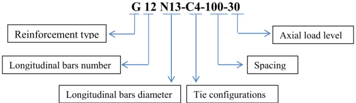
Figure 3.3 – Identification key 44
Figure 3.4 – Concrete dimensions and the reinforcement details 45
Figure 3.5 – Concrete dimensions and reinforcement details 46
Figure 3.6 – Spacing details 47
Figure 3.7 – Configuration details 48
Figure 3.8 – Elevation details 49
Figure 3.9 – Cross-section details 50
Figure 3.10 – Reinforcement details 51
Figure 3.11 – Base formwork and cages 54
Figure 3.12 – Instrumented Columns cages 55
Figure 3.13 – Column cage into the base 56
Figure 3.14 – Align the columns formworks 57
Figure 3.15 – Casting the base 57
Figure 3.16 – Ready mix concrete and pump truck 58
Figure 3.17 – Pouring concrete into columns‗ formworks 58
Figure 3.18 – Cured columns ready for testing 59
Figure 3.19 – LVDTS instrumentation 60
Figure 3.20 – Strain gauges instrumentations 60
Figure 3.21 – Test set-up 61
xiv
Figure 4.1 – Test specimen details 70
Figure 4.2 – Instrumentation of test specimens 74
Figure 4.3 – Test setup 75
Figure 4.4 – Loading history 75
Figure 4.5 – Hysteretic response 77
Figure 4.6 – Crack pattern and plastic hinge 79
Figure 4.7 – Typical failure progression of the steel-reinforced columns 80 Figure 4.8 – Typical failure progression of the GFRP-reinforced columns 81
Figure 4.9 – Idealized curve definition 84
Figure 4.10 – Definition of energy dissipation 87
Figure 4.11 – Accumulated energy dissipation 88
Figure 4.12 – Experimental and estimated drift ratios 92
Figure 4.13 – Typical strain in rectilinear spirals and cross ties (G12N13-C4-100) 93 Figure 4.14 – Strain in the rectilinear spirals and cross ties in the tested columns 94 Figure 5.1 – Idealized load–displacement curves for tested column specimens 101 Figure 5.2 – Calculation of ductility-related response modification factor (Rd) 103
Figure 5.3 – Experimental and estimated drift ratios 106
Figure 5.4 – Tri-linear shape of the measured curvature distribution 108
Figure 5.5 – Plastic hinge length 109
Figure 5.6 – Strain distribution profile 111
Figure 5.7 – Elastic and plastic displacements and Rotations 113
Figure 5.8 – Elastic curvature 114
INTRODUCTION
1
CHAPTER 1: INTRODUCTION
1.1
General
Using of Fiber Reinforced Polymers-FRP- reinforcement as alternative to steel reinforcement is
being explored in all members of the new concrete structures such as slabs, beams, columns, shear walls, squat walls and shear walls. The reasons for increase in demand and usage of FRP reinforcement in the civil engineering industry are as follows:1. FRP reinforcement possess many desirable features including high strength to weight ratio, non-conductivity, electro-magnetic transparency, favorable fatigue strength and low relaxation characteristics.
2. The long term cost and effectiveness of FRP reinforcement when used in corrosive environments like chemical plants, waste-water treatment plants, marine structures and industrial cooling towers encouraged structures owners and governments to use these kind of materials.
3. The deterioration state of the infrastructures which requires restoration and maintenance proceedings, opens the door for FRP reinforcement not just in rehabilitation and strengthening of existing structures but also as alternative to steel reinforcement in the new structures.
All the previous characteristics enabled FRP bars and stirrups to be good replacement to steel bars and stirrups respectively, however, the stress-strain relationship for FRP bars is linear elastic up to failure without a yielding plateau as happens in the case of steel bars. This raises concerns about the applicability of using FRP bars in reinforcing concrete structural members exposed to seismic activities. Inquiries for the behavior of FRP reinforced concrete structures regarding the deformability, strength, and energy dissipation need to be explored. These characteristics are essential for concrete structural members exposed to seismic actions like earthquakes and wind loads.
The ductility of earthquake resistant structures assures the ability and capacity of the structural elements to absorb and dissipate energy under seismic loads without a significant loss of strength. Due to the inelastic behavior of the structural element, the plastic hinge might be developed. The plastic hinge is the region where the inelastic deformations appear and in return dissipate the
INTRODUCTION
2
absorbed energy. Consequently, reinforced concrete columns have to provide an important inelastic response without a significant decrease of strength capacity. In order to guarantee the ductile behavior of the columns, codes specify the transverse reinforcement ratio provisions to be included in critical zones where a plastic hinge could be developed. In spite of all previous favorable characteristics of FRP reinforcement in new structures, there is a lack in informations regarding the performance of FRP–reinforced columns subjected to lateral reversed loads as in case of earthquakes resistant elements. The present study investigates the performance of GFRP-reinforced concrete columns.
1.2
Research objectives
The main objective of the current research is to investigate the behavior of GFRP-reinforced concrete columns subjected to quasi-static reversed cyclic loading, and to develop design equations for such structural element. Experimental research is needed to verify the applicability of GFRP-reinforced concrete columns under seismic loading. The objectives of the current study can be summarized as follows:
Design the GFRP-reinforced concrete columns with a dominant flexural behavior in accordance with previous works and design codes guidelines.
Investigate the ultimate load capacity.
Investigate the lateral drift ratio, deformability and energy dissipation.
Assessthe seismic behavior and the deformability within the inelastic range of concrete. Evaluate the plastic hinge length and ductility related force modification factors needed in
the design.
Propose simplified equation for calculating the deformation capacity and compare the calculated deformation capacity with the needed deformation demand.
1.3
Methodology
To achieve the objectives of this research, the following steps are followed:
Review the design guidelines in available codes concerning the seismic design of laterally loaded FRP-reinforced concrete elements.
Review of previous researches on the behavior of concrete columns reinforced with steel and FRP bars.
INTRODUCTION
3
Design, constructing, and testing nine large-scale GFRP reinforced concrete columns in addition to two steel reinforced concrete columns which serve as control specimens.
Analyze the experimental results regarding hysteretic response, lateral drift ratio, deformability, energy dissipation, ultimate load capacity.
1.4
Thesis outlines
The thesis includes six chapters; chapter 1 presents general information on GFRP reinforcement including the advantages of using these materials. The objectives and the methodology of the present study are also included in this chapter. Chapter 2 reports the literature review on steel and FRP reinforced structural members. Chapter 3 includes the experimental program and the followed design philosophy of FRP reinforced concrete elements. Chapter 4 shows the experimental results and analysis. Chapter 5 provides proposed equations for designing GFRP reinforced concrete columns based on displacement capacity. Chapter 6 includes conclusions and recommendations for the future studies based on present study.
INTRODUCTION
Chapter 2: Literature review 5 Stress 1800-4900 600-3000 34-130 0.4-4.8 % > 10 % Strain Fibres FRP matrix
CHAPTER 2: LITERATURE REVIEW
2.1
FRP Composite Materials
2.1.1 General
FRPs are being used in many fields like the aeronautical, aerospace and automotive fields since five decades. The use of FRPs in civil engineering started in 1950s when GFRP bars were considered. However, it was not until the 1970s that FRP was finally considered for structural engineering applications. Since their early application, many different types of fibers have been developed including aramid, polyvinyl, carbon and improved glass fibers. Also different shapes and forms have been manufactured such as bars, fabric, 2D grids, 3D grids or standard structural shape.
2.1.2 Constituents
FRP products are composite materials consisting of a matrix (resin) and reinforcing fibers. The fibers have higher strength than the matrix as shown in Figure 2-1. For reinforcing demands, the fiber-volume fraction should be more than 55 percent for FRP bars and rods and 35 percent for FRP grids (ISIS 2007). The mechanical properties of the final FRP product depend on the fiber quality, orientation, shape, volumetric ratio, adhesion to the matrix, and on the manufacturing process.
Chapter 2: Literature review
6
2.1.2.1 Fibers
High strength and stiffness, toughness, durability and low cost are the main characteristics for the fibers used in manufacturing FRP composite materials. The performances of fibers depend on the fibers length, cross-sectional shape and the chemical composition. Different types, cross-sectional shapes and sizes of fibers are available. The most common fibers are carbon, glass and aramid fibers.
2.1.2.2 Resins
The physical and thermal properties of the matrix significantly affect the final mechanical properties as well as the manufacturing process. To achieve the full strength of the fibers, the matrix should be able to develop a higher ultimate strain than the fibers (Phillips, 1989). Matrix is used for coating the fibers and protecting them from mechanical abrasion, transferring stresses between the fibers, transferring inter-laminar and in-plane shear in the composite, also providing lateral support against fibers buckling. There are two types of polymeric matrices used for FRP composites; namely, thermosetting and thermoplastic.
2.1.3 Manufacturing Process
There are three common manufacturing processes for FRP materials; pultrusion, braiding, and filament winding. Pultrusion is a common technique for manufacturing continuous lengths of FRP bars that are of constant or nearly constant profile. A schematic representation of this technique is shown in Figure 2-2. Continuous strands of reinforcing material are drawn from creels, through a resin tank, and then through a number of wiper rings into the mouth of a heated die. To ensure good bond with concrete, the surface of the bars is usually braided or sand-coated. Braiding is a term used for interlocking two or more yarns to form an integrated structure. Filament winding is a process whereby continuous fibers are impregnated with matrix resin and wrapped around a mandrel (ISIS2007).
Chapter 2: Literature review
7
Figure 2-2: Pultrusion process
2.1.4 Physical properties
2.1.4.1
DensityFRP bars have a density ranging from 1.25 to 2.1 g/cm3, one-sixth to one-fourth of that of steel. Reduced weight lowers transportation costs and may ease handling of the cages during construction. Table 2.1 lists different types of FRP bars densities.
Table 2.1: Typical densities of different FRP bars (ACI 440.1R-15)
Steel GFRP CFRP AFRP
7.9 1.25 to 2.10 1.50 to 1.60 1.25 to 1.40
2.1.4.2
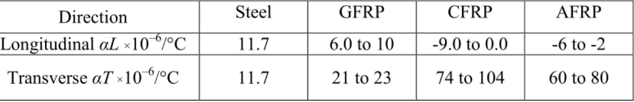
Coefficient of thermal expansionThe coefficients of thermal expansion of FRP bars vary in the longitudinal and transverse directions depending on the types of fiber, resin, and volume fraction of fiber. The longitudinal coefficient of thermal expansion is dominated by the properties of the fibers, while the transverse coefficient is dominated by the resin (Bank 1993). Table 2.2 lists the longitudinal and transverse coefficients of thermal expansion for typical FRP and steel bars.
Table 2.2: Typical Coefficient of thermal expansion for reinforcing bars(ACI 440.1R-15)
Direction Steel GFRP CFRP AFRP
Longitudinal αL ×10–6/°C 11.7 6.0 to 10 -9.0 to 0.0 -6 to -2 Transverse αT ×10–6/°C 11.7 21 to 23 74 to 104 60 to 80
Chapter 2: Literature review
8
2.1.5 Mechanical
properties
2.1.5.1
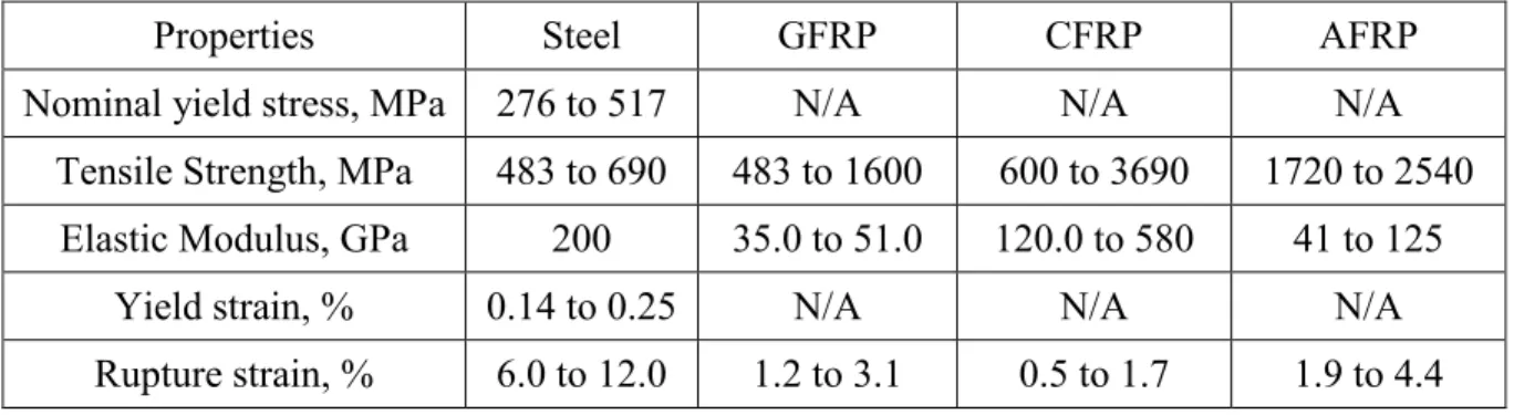
Tensile behaviorThe tensile behavior of FRP bars consisting of one type of fiber material is characterized by a linearly elastic stress-strain relationship until failure. The tensile properties of some commonly used FRP bars are summarized in Table 2.3. The tensile strength and stiffness of an FRP bar are dependent on several factors. Because the fibers in an FRP bar are the main load-carrying constituent, the ratio of the volume of fiber to the overall volume of the FRP (fiber-volume fraction) significantly affects the tensile properties of an FRP bar (Wu 1990).
Table 2.3 - Tensile properties of reinforcing bars (ACI 440.1R-15)
Properties Steel GFRP CFRP AFRP
Nominal yield stress, MPa 276 to 517 N/A N/A N/A Tensile Strength, MPa 483 to 690 483 to 1600 600 to 3690 1720 to 2540
Elastic Modulus, GPa 200 35.0 to 51.0 120.0 to 580 41 to 125
Yield strain, % 0.14 to 0.25 N/A N/A N/A
Rupture strain, % 6.0 to 12.0 1.2 to 3.1 0.5 to 1.7 1.9 to 4.4
2.1.5.2
Compressive behaviorWhile it is not recommended to rely on FRP bars to resist compressive stresses, the following researches are presented to fully characterize the behavior of FRP bars. Tests on FRP bars with a length-diameter ratio from 1:1 to 2:1 have shown that the compressive strength is lower than the tensile strength (Wu 1990). The mode of failure for FRP bars subjected to longitudinal compression can include transverse tensile failure, fiber micro-buckling, or shear failure. The mode of failure depends on the type of fiber, the fiber-volume fraction, and the type of resin. Compressive strengths of 55, 78, and 20% of the tensile strength have been reported for GFRP, CFRP, and AFRP, respectively (Mallick 1988; Wu 1990). In general, compressive strengths are higher for bars with higher tensile strengths, except in the case of AFRP, where the fibers exhibit nonlinear behavior in compression at a relatively low level of stress.
Chapter 2: Literature review
9
2.1.5.3
Shear behaviorMost FRP bar composites are relatively weak in inter-laminar shear where layers of unreinforced resin lie between layers of fibers. Because there is usually no reinforcement across layers, the inter-laminar shear strength is governed by the relatively weak polymer matrix. Orientation of the fibers in an off-axis direction across the layers of fiber will increase the shear resistance, depending upon the degree of offset. If the shear properties of a particular FRP bar are needed, these should be obtained from the bar manufacturer. The manufacturer should provide a description of the test method used to obtain the reported shear values (ACI 440.1 R-15).
2.1.5.4
Bond behaviorBond performance of an FRP bar is dependent on the design, manufacturing process, mechanical properties of the bar itself, and the environmental conditions (Al-Dulaijan et al. 1996; Nanni et al. 1997; Bakis et al. 1998; Bank et al. 1998; Freimanis et al. 1998). The bond properties of FRP bars have been extensively investigated by numerous researchers through different types of tests, such as pullout tests, splice tests, and cantilever beams, to determine an empirical equation for embedment length (Faza and GangaRao 1990; Ehsani et al. 1996; Benmokrane 1997; Shield et al. 1999; Mosley 2002; Wambeke and Shield 2006; Tighiouart et al. 1999).
2.2 Literature Review
2.2.1 General
The use of GFRP reinforcement in concrete members like columns under seismic loading is suffering lack and shortage of data and guidelines in codes due to lack in researches. Few researches were conducted on axial compression columns reinforced with FRP bars (Pantelides et al. 2013, Tobbi et al. 2012). Also, FRP jackets and sheets were used as a confinement for the columns (Purba and Mufti 1999, Deniaud and Neale 2005). FRP materials were used also for rehabilitation and strengthening of existing structures (Zafra and Kawashima 2013, Shan et al. 2006). Beam-column joints were studied by Mady et al. (2011), and Said and Nehdi (2004). FRP-reinforced structural walls had been studied by Yamakawa and Fujisaki (1995), Mohamed et al. (2014). Previous researches for FRP reinforced concrete columns under seismic loading are limited (Tavassoli et al. 2015 and Ali and El-Salakawy
Chapter 2: Literature review
10
2016), therefore the following section summarizes the available conducted researches on steel and FRP reinforced concrete columns.
2.2.2 Steel reinforced concrete columns under simulated seismic loading
Many experimental and analytical studies were carried out on steel reinforced concrete columns under different types of loading; concentric and eccentric compression, monotonic lateral loading, reversed lateral loading and simulated seismic loading (axial compression and reversed lateral deformations). Many codes and specifications include guidelines and provisions for columns‘ design; involve equations to determine the section dimensions and the required amount of steel reinforcement. The main demand for structures in seismic zones is the ductility capacity, the structures with ductile behavior have the ability to absorb and dissipate energy under seismic loads without significant loss in strength through plastic hinges. The capacity of ductile structures to dissipate energy is taken into account in the seismic design of concrete structures in all codes. A safe ductile behavior and failure for a structure can be reached by guarantee strong column-weak beam concept. However, according to Hwang and Yun (2004), it has been stated that hinges appear at the ends of the columns after an earthquake.
Caballero et al. (2012) performed an experimental study on the behavior of slender columns subjected to combinations of constant axial and lateral cyclic loads. Figure 2-3 shows the concrete dimensions and reinforcement details. Fourteen specimens were constructed and tested. The researchers used the results to calibrate numerical models and to validate simplified methods. The studied parameters were: slenderness, axial load level, transverse reinforcement ratio, and volumetric steel-fiber ratio. The strength and deformation capacity of the columns are analyzed. It was concluded that the deformation capacity depends on the chosen parameters. Using steel fibers and the minimum transverse reinforcement into the concrete mixture increases the deformation capacity. Also the slenderness of the column influences the deformation capacity.
Chapter 2: Literature review
11
Figure 2-3: Slender concrete columns details. (Caballero et al. 2012)
Grira and Saatcioglu (1998) tried to develop economically feasible new techniques for columns confinement. Thirty one full scale reinforced concrete columns were constructed and tested under simulated seismic loading. Thirteen columns confined with welded steel grids, of which 3 columns were built of high strength concrete, 4 columns confined with steel hoops and double head studs, and 14 columns confined with fiber reinforced plastic grids. The columns specimens were chosen to be representatives of a lower portion of a first floor column between the footing and the point of inflection with a 1645 mm shear span and cross-sectional dimensions of 350×350 mm. The dimensions of the columns were chosen to guarantee flexural dominant behavior. The columns were confined following the spacing requirements of ACI 318 (1995). The studied parameters were compressive strength of concrete, arrangement of longitudinal bars, volumetric ratio of transverse reinforcement, vertical spacing of grids and level of the axial load. The authors concluded that the welded reinforcement grids can be used effectively as confinement reinforcement provided that the steel has sufficient ductility and without noticeable loss in strength. The specimens showed 7 to 10% strain prior to failure and producing lateral drift ratios (the lateral displacement divided by the shear span) in excess of 3% with volumetric ratios less than those required by ACI 318 (1995) building code. For the concrete columns confined with double head studs and conventional perimeter hoops also showed ductile behavior, developing lateral drifts of 4 to 6% prior to a significant loss moment capacity. The concrete column properly confined with FRP grids showed ductile response and behaved as well as the companion columns confined with welded steel grids. The failure of those columns was caused mostly by crushing of compression concrete but in few columns, premature failure of FRP grids at the joints had happened. 150 Section A-A 150 Section B-B B B 1320 300 1320 6 ɸ (12 or 8) 8mm@50, 70 and 100
Chapter 2: Literature review
12
Saatcioglu and Baingo (1999) studied the behavior of high strength steel reinforced concrete columns under simulated seismic loading. The studied parameters were the concrete strength, axial load level, confinement steel grade, volumetric ratio of transverse reinforcement and spacing. The authors concluded that the increased confinement required for HSC columns can be provided by increasing the volumetric ratio and/or yield strength of transverse steel. Deformability of HSC columns decreases with increasing axial compression. Individual circular hoops are as effective as continuous circular spirals in confining HSC columns; however, the spiral reinforcement appears to be more effective in improving stability of longitudinal reinforcement at later stages of inelastic deformations. Figure 2-4 shows the concrete dimension and reinforcement details.
Figure 2-4: High strength circular concrete columns details (Saatcioglu and Baingo 1999)
Samuel et al. (2011) designed and constructed 600 mm square cross section columns and 1200 mm in length with 10 different steel configurations as shown in Figure 2-5 to study the effect of tie configuration on column seismic behavior.
Section A - A 8-16 mm bars 10 mm Cover Spiral A A D=250 1100
Chapter 2: Literature review
13
Figure 2.5 - Confinement Configuration details (Samuel et al. 2011)
(a) conventional; (b) single bar; (c) welded wire grid; (d) three welded hoops; (e) twin hexagonal; (f) twin elliptical; (g) four spiral; (h) five spiral; (i) spiral plus cross ties; and (j) spiral plus four ears.
Sixteen No. 8 (area = 506.7 mm2) longitudinal bars with a yield strength of 412 MPa were used for all specimens. The results clearly verified that columns with interlocking multi-spiral confinement design exhibited higher compressive strength and ductility when compared to columns with conventional rectilinear hoop design.
Yeh and Shamim (1990) studied the seismic behavior of steel reinforced concrete columns, confined by rectilinear ties. 305 mm square cross section columns with length 2740 mm were tested under flexure to large inelastic deformations while simultaneously subjected to constant axial load. The studied parameters were distribution of longitudinal and lateral reinforcement, the axial load level, and amount of lateral reinforcement and spacing of ties. The result showed that large number of laterally supported longitudinal bars results in higher flexural strength and ductility. At small tie spacing for the same amount of transverse reinforcement, higher strength and ductility were found with precautions of lateral steel anchorage. 26% excess in flexural capacity was observed due to the confinement. The maximum values of curvature ductility factor and the compressive concrete strain corresponding to the maximum moment were above 50 and 0.019, respectively. In case of unsupported longitudinal bars, the
Chapter 2: Literature review
14
bars suffered buckling at large deformations, resulting in brittle failure due to losing the needed confinements. Higher axial load reduces strength and ductility of confined concrete sections very significantly. Flexural behavior enhancement could be obtained at case of increasing the amount of lateral reinforcement.
Bayrak and Shamim (1998) studied experimentally the confinement of high-strength concrete (HSC) and ultrahigh-strength concrete (UHSC) column with lateral steel reinforcement on columns seismic behavior. 305 mm square cross section columns with 1473 mm in length tested under different axial load levels and reversed cyclic displacement. The studied parameters were the concrete strength, axial load level, steel configuration, and amount of lateral steel. A comparison between the behavior of normal strength concrete column and HSC and UHSC columns was done. The authors reported that HSC and UHSC could behave in ductile manner if a sufficient amount of confinement is used in an efficient configuration. A high confined 102 MPa concrete columns displayed a very ductile behavior showing a curvature ductility factor of 14 and displacement ductility factor of 6.3. The authors concluded that the rectilinear ties had high effect on the columns ductility. Better distribution of reinforcement and better lateral support to the longitudinal bars provided tougher response of UHSC columns, which is similar to the ones observed for NSC and HSC columns. An increase in axial load reduces the column's deformability and ductility and, also, accelerates strength and stiffness degradation with every load cycle. It was mentioned that, the amount of lateral reinforcement to reinforcement configuration and the level of axial load must be considered in the design of confinement reinforcement.
Yun (2003) had an experimental and analytical study on high strength concrete columns under seismic loading. 510 mm square cross sections columns were reinforced with 4 No.29 and 4 No.36 as longitudinal steel reinforcement with a ratio of 2.6% of the column gross sectional area. The studied parameter was the transverse reinforcement details. The authors concluded that the deformability and behavior of the columns were extremely affected by the amount and details of the transverse reinforcement in the plastic hinge region as well as the axial load levels. 6% drift ratio was reached without degradation of load carrying capacity at case of columns with 82% or more of confinement specified in the seismic design provision of the ACI 318 (1995) code when the axial load ratio was 20%. Increasing the applied axial load
Chapter 2: Literature review
15
level resulted in decreasing the ultimate drift ratio and deformability of the columns. 4% drift ratio was reached in case of 52% of confinement specified in the seismic design provision of the ACI 318-95 code when the axial load ratio was 20%. A micro-analysis was performed with ADINA by constructing three-dimensional finite element models. The results, with all parameters properly prescribed, provided good correlation with the experimental values. The finite element method could provide detailed analytical results of stress and crack distributions and provided insights in stress and crack variations during the stages of loading as well as verification of the experimental results.
Bae and Bayrak (2008) had an experimental and analytical study to estimate the plastic hinge length of reinforced concrete columns. The effect of axial load level and shear span to depth ratio (L/h) were studied. Based on the experimental results, it was concluded that the level of axial load influenced the length of the plastic hinge. Specimens tested under high axial loads developed longer plastic hinge lengths than those tested under low axial loads. The following equation was proposed to estimate the length of the plastic hinges forming in RC columns:
* ( ) ( ) + ( )
where,
lp : Plastic hinge length. h : Overall depth of column. P : Applied axial load.
Po : Nominal axial load capacity. As : Area of tension reinforcement. Ag : Gross area of concrete section.
L : Distance from critical section to point of contraflexure.
Mortezaei and Ronagh (2013) had 1316 inelastic time-history analyses that been performed to predict the nonlinear behavior of RC columns under both far-fault and near-fault ground motions. The axial load level, height over depth ratio, amount of longitudinal reinforcement, and different characteristics of earthquakes effects on column seismic behavior were evaluated
Chapter 2: Literature review
16
analytically by finite element methods. The results were compared with corresponding experimental data. Based on the results, the following expressions were proposed to be used to estimate plastic hinge length of RC columns subjected to both far-fault and near-fault earthquakes that contain a forward-directivity effect.
For far fault earthquakes:
* ( ) ( ) + ( )
For near fault earthquakes:
* ( ) ( ) + ( )
where,
h : Overall depth of column. P : Applied axial load.
P0 : Nominal axial load capacity. As : Area of tension reinforcement. Ag : Gross area of concrete section.
L : Distance from critical section to the point of contraflexure.
Ho (2011) constructed eight 325 × 325 mm square cross-section columns with a height of 1515 mm to study the structural parameters affecting the flexural ductility of high-strength reinforced concrete (HSRC) columns under constant compressive axial load and reversed cyclic displacements. The specimen represented a real column in an RC moment-resisting framed building between the contra-flexure and the maximum bending moment points, which are located around the mid-height and at the face of the beam-column joint respectively. The reinforcement ratio of the longitudinal steel bars varied from 0.9 to 6.1%. The confining steel content within critical region was calculated using the following equation:
( ) ( ) ( ) ( )
Chapter 2: Literature review
17
While that outside the critical region was designed to resist the ultimate shear force only. From the test results, it is evident that ultimate curvature ductility factors obtained for all the column specimens were close to 10, which is considered the standard for limited ductility. The design is thus suitable for HSRC columns of tall buildings in regions having low to moderate seismic risk where the design of fully ductile columns is too generous and/or not necessary.
Gajalakshmi and Helena (2012) studied experimentally the behavior of concrete-filled steel tube columns subjected to lateral cyclic loading. The studied parameters were the diameter-to-thickness ratio of the steel tube and two types of in-fills namely plain cement concrete and steel fiber reinforced concrete. The authors concluded that steel fiber reinforced concrete-filled steel tube (SCFT) columns, exhibited about 1.5 to 2 times the energy absorption capacity of plain cement concrete-filled steel tube, enhanced ductility and reduced damage index compared to concrete-filled steel tube (CFT) columns.The failure pattern of the specimens are found to be governed by diameter of columns-to-thickness ratio of the columns and are independent of the type of in-fill and type of loading pattern.
2.2.3 FRP Reinforced concrete members
2.2.3.1 Columns under axial compression only
Tobbi et al. (2012) performed an experimental study on concrete columns, reinforced longitudinally and transversally with GFRP bars. The specimen cross-section dimensions were 350х350 mm with a height of 1400 mm. Figure 2-6 shows the concrete dimensions and reinforcement details. The specimens tested under concentric load to investigate the behavior of GFRP internally reinforced concrete columns and comparing it with steel control specimen. The studied parameters were the longitudinal reinforcement ratio, transverse reinforcement spacing and ties configurations. The authors concluded that the tie configurations and spacing had a clear influence on GFRP columns in increasing the strength, stiffness and ductility of the confined concrete core. The strength reduction factor 0.85 (at case of steel) can be adopted for GFRP reinforced concrete columns. The GFRP bars could contribute 10% of the columns capacity which reveals the possibility of using GFRP bars in compression members, however, adequate confinement is needed for avoiding the bars local buckling.
Chapter 2: Literature review
18
Figure 2-6: Square GFRP-reinforced concrete columns details (Tobbi et al. 2012)
Pantelides et al. (2013) evaluated the GFRP spiral confinement behavior for longitudinal GFRP and steel reinforced concrete columns under axial compression loads. It was concluded that hybrid control and entirely GFRP-reinforced columns achieved 87 and 84% of the axial load capacity of the entirely steel-reinforced control column, respectively. To achieve a similar performance to entirely steel-reinforced columns, hybrid columns must be reinforced with a larger GFRP spiral reinforcement ratio. Entirely GFRP-reinforced columns must be reinforced with a larger reinforcement ratio for both GFRP vertical bars and GFRP spirals.
Wu (1990) reported that the compressive strength of FRP bars were lower than their tensile strength. Accordingly, the compressive strength of GFRP, CFRP and AFRP bars were 55%, 78% and 20% of their tensile strengths, respectively.
2.2.3.2 Columns under eccentric loads
Paramanantham (1993) studied the behavior of FRP reinforced concrete columns under concentric and eccentric loading. Fifteen FRP-reinforced concrete blocks and 16 columns were constructed and tested under concentric and eccentric loading, respectively. The longitudinal and transverse reinforcement were GFRP bar type. The fifteen FRP-reinforced
Chapter 2: Literature review
19
concrete blocks were tested to investigate the concentric capacity of specimens as affected by tie spacing and bar local buckling. The studied parameter – tie spacing – was chosen as 100, 150, and 200 mm. The authors concluded that no major difference for the concentric capacity due to tie spacing, but it was noticed that small improved strength due to better control for buckling of FRP reinforcement in the case of 100 mm tie spacing. FRP bars contributed to the load carrying corresponding to 0.003 strains. This represented 20-30% of the ultimate strength of FRP reinforcement. The other specimens (16 columns) tested under different axial loading and moment combinations. All the specimens failed in compression crushing mode. The columns behavior was characterized upon the ratios of moment-deflection relationships slopes into three parts, the first and the second parts were linear, but the third part was nonlinear. When the ratio of first to second slope varied between 1.25 and 1.85, the failure was defined as compression failure. When the ratio varied between 2.22 and 2.37, the failure was defined as compression with tensile cracking. When the ratio varied between 5.5 and 6.0, the failure was defined as compression-flexure failure. It was also concluded that the best results were produced using a transverse spacing 100 mm. The maximum tensile stress measured in FRP bars was about 70% of their ultimate tensile strength in direct tension. The experimental results were compared with a moment axial force interaction diagram derived analytically on the basis of the plane section analysis. The comparison showed that the experimental strength values were higher than those computed analytically except for four columns. The compression-controlled portion of interaction diagrams was similar for both FRP and steel reinforced columns but the tension governing portions were different. At last, the researchers developed equations for calculating column capacities under concentric and eccentric axial loads.
For concentric loading, the axial capacity of the column (Pn) can be calculated as:
׳( ) For columns under eccentric loading:
׳
׳
Chapter 2: Literature review
20
where,
׳ : Compressive concrete strength. Cc : Force carried by concrete.
Cf : Force carried by the bars in compression. Tf : Force carried by the bars in tension. Ag : Gross cross sectional area.
Af : Area of FRP reinforcement fibers.
Ef : Tensile modulus of elasticity of FRP bars.
β1 : Ratio of depth of rectangular compression block to depth to the neutral axis. A : Depth of equivalent rectangular stress block.
B : Width of compression face of the member. ׳ : Compressive strain of FRP bars.
Efc : Compressive modulus of elasticity of FRP bars. εt : Tensile strain of FRP bars.
2.2.3.3 Columns under cyclic lateral load
Similar reduction in strength was reported by Kobayashi and Fujisaki (1995). The researchers conducted materials tests on FRP bars, as well as FRP reinforced columns tests under monotonic and reversed cyclic loading, the FRP bars were CFRP, AFRP and GFRP bars. The FRP bars were embedded in concrete and subjected to compression. The compressive capacity was 30 to 50% for CFRP, 10% for AFRP and 30-40% for GFRP bars of their tensile capacity. The same bars were subjected to incrementally increasing axial tension and compression reversals, AFRP and GFRP bars showed a reduction of 20-50% in their compressive capacity not like the CFRP bars which did not show any significant reduction in the strength. All the bars failed in compression and the tension capacity was not affected by reversing the load. Also 200 mm square cross-section and 650 mm height concrete columns and reinforced with CFRP, AFRP and GFRP hoops were studied. The researchers observed that the strain compatibility was maintained up to the crushing of concrete, the columns reached concentric capacity at 0.25-0.4% compressive strains. The FRP bars continued straining up to 1.00 to
Chapter 2: Literature review
21
1.8% in compression, beyond the peak column load, before they failed in compression. The researchers suggested that the concentric capacity of FRP reinforced concrete columns could be computed by using the gross area of the column, multiplied by 85% of concrete strength with neglecting the FRP bars contribution. The researchers also reported that under strain gradient, plane section analysis could be employed with failure governed by concrete crushing. The researchers reported also that the column strength and behavior were not affected by FRP compression failure in compression zone but those bars were not expected to resist subsequent tension after load reversing.
Zafra R., G. and Kawashima K. (2009) studied experimentally and analytically the behavior of CFRP sheet-retrofitted RC bridge columns under lateral cyclic loading. It was concluded that the fiber element analysis using constitutive models for concrete confined by both CFRP sheet and tie reinforcement provides good numerical simulation of the experimental results. The failure mode and progress of failure of the columns can be well explained based on the fiber element analysis. As CFRP sheet ratio increases, flexural strength and ductility of CFRP sheet-retrofitted columns also increases. However, as tie reinforcement ratio increases, there is no much difference on the hysteretic response for low tie reinforcement ratios.The hysteretic response of as-built columns can be enhanced by CFRP sheet jacketing which effectively increases lateral confinement, allowing an increase in flexural strength and ductile behavior. Simulation of the 7.5 m tall pier under a large earthquake shows that CFRP sheet retrofit increases the flexural strength of the as-built pier while limiting its displacement.
Sharbatdar (2003) studied experimentally the behavior of full-scale square columns and rectangular beams reinforced with CFRP bars and stirrups under seismic loading. Based on characterization testing, the used CFRP bars had compression strength and modulus of elasticity of 16-21% and approximately 20% of their corresponding tensile properties, respectively. The authors concluded that columns with 30% of the confinement reinforcement required by the CSA S806 (2002) had a brittle behavior shortly after 2.0% lateral drift ratio. Also, those columns showed a 50% drop in flexural capacity at 3.0% drift ratio. On the other hand, columns that had 60% of the confinement reinforcement required by CSA S806 (2002) showed increased deformability with lateral drift ratio up to 3.0% associated with approximately 23% strength degradation. In general, all the columns specimens sustained
Chapter 2: Literature review
22
lateral drift ratios higher than the limits specified by the national building code of Canada (1995)
Ozbakkaloglu and Saatcioglu (2007) studied the seismic performance of square high-strength concrete columns in FRP stay-in-place formwork. The columns had 270 mm square sections and concrete strengths up to 90 MPa. Figure 2-7 shows the concrete dimensions and reinforcement details. The studied parameters were the introduction of the corner radius, validity of FRP casing for confinement and the presence of internally placed FRP crossties. Results indicated that the deformation capacity of HSC columns can be improved significantly by using FRP casings. The results further indicate that the confinement effectiveness of columns is significantly affected by the corner radius of casings. Additionally, the confinement efficiency can be improved with the use of FRP crossties. The columns developed inelastic drift capacities of up to 11%, demonstrating the usefulness of FRP stay-in-place formwork in improving deformability of HSC columns.
Figure 2-7: Square high strength concrete column details (Ozbakkaloglu and Saatcioglu 2007) 250 1100 1720 5 1 3 6 5 500 FRP crossties 8#15 bars R= 45mm 270 mm 270 m m FRP crossties R= 45mm 270 mm 8#15 bars 270 m m R= 45mm 270 mm 12#15 bars 270 m m R= 8 mm 270 mm 8#15 bars 270 m m R= 45mm 4#20 bars 270 mm 270 m m
Chapter 2: Literature review
23
Dong et al. (2012) studied experimentally and analytically the effect of FRP Jacket as external confinement for steel reinforced concrete columns under seismic loading on the plastic hinge length as well as the drift capacity of FRP confined circular concrete columns. The experimental results and the obtained plastic hinge model showed that FRP confinement increased the plastic hinge length at low confinement ratio, however, it had an opposite effect when the confinement ratio is high. The ultimate drift ratio of a column was affected by its axial load level, confinement ratio, and aspect ratio. Confinement at a low level increased the drift capacity of the column. However, after a critical value had been exceeded a further increase in confinement will cause a reduction in the deformation capacity of the column.
Choo et al. (2006) performed an analytical study on short and slender FRP reinforced concrete columns to investigate the seismic behavior of FRP-RC columns and to study the axial-moment-curvatures relations. The authors concluded that unlike steel, FRP-RC columns did not exhibit balance points bound by the reinforcement limits [(ρmin = 1%) ≤ ρ ≤ (ρmax = 8%)] defined by the ACI 318 (2005). The FRP-RC columns were tending to brittle tension failure according to this study. Ignoring the contribution of FRP reinforcement in the compression zone may be conservative. However, the ultimate compressive strain of FRP reinforcing bars must be checked to ensure that compressive failure does not occur in FRP bars.
Tavassoli et al. (2015) studied experimentally nine GFRP reinforced circular concrete columns under simulated seismic loading. The specimens were reinforced longitudinally and transversally with GFRP bars and spiral. The specimen diameter and length were 356 mm and 1473 mm respectively as shown in Figure 2.8. The column was tested in away resulted in 1841 mm shear span. The studied parameters were the spiral diameter; spacing and axial load level also two different types of GFRP bars and spiral were used. The authors concluded that the GFRP columns had a stable seismic performance as well as high drift ratios reached 9% in some columns. The confinement level is very effective parameter also it is more critical for high axially loaded columns. Columns with higher axial loads showed more damage and lower level of deformability. The authors concluded that GFRP bars can be successfully used as internal reinforcement in ductile concrete columns.
Chapter 2: Literature review
24
Figure 2.8 – GFRP-reinforced circular concrete column details (Tavassoli et al. 2015)
Ali and El-Salakawy (2016) studied experimentally eight reinforced concrete columns subjected to simulated seismic loads. Seven of the specimens were reinforced with GFRP bars and stirrups while one was reinforced with steel bars and stirrups as a control specimen. The specimen had a 350 mm square cross section and a shear span of 1650 mm as shown in Figure 2.9. The studied parameters were the longitudinal ratio, spacing and the axial load level. The authors concluded that all the columns reached high drift ratio around 8.5%. The dissipated energy of GFRP column was 50% of counter steel one at 4% drift ratio. Increasing the reinforcement ratio resulted in increasing the lateral capacity while decreasing the deformation capacity. Increasing the confinement level for column plays important role in increasing the drift capacity. Increasing the axial load results in rapid deterioration and decreasing the strength and drift capacity.
Chapter 2: Literature review
25
Figure 2.9 – GFRP-reinforced square concrete column details (Ali and El-Salakawy 2016)
2.2.3.4 Beam-column joint under cyclic lateral load
Sharbatdar et al. (2011) constructed and tested three large-scale FRP reinforced concrete joints under cyclic loading. The specimens were T-shape joints consisting of two columns and one beam representing half portion of the first and the second floor of one-bay reinforced concrete frame, or exterior joint of frames with more than one bay. Figure 2-10 shows the concrete dimensions and reinforcement details. The columns subjected to constant axial load meanwhile the beams subjected to reversed cyclic loading. The joint reinforced with CFRP bars as longitudinal reinforcement and CFRP grids as transverse reinforcement. Spacing of CFRP grids and arrangement of longitudinal CFRP bars were the main test parameters. The results indicated that FRP reinforcement can be used effectively in new concrete buildings, the joint drift capacity can be in excess of 3%. FRP bars were capable of resisting the significant compression and tension–compression cycles without any distress. The strength and elastic modulus of FRP bars in compression were approximately equal to 20% of the values in tension. The failure in tension occurred at about 1.0% strain. Also more bars arrangement
550
Chapter 2: Literature review 26 2100 483 8 or 12 of (12.7 mm diameter) 12-Cell grids 3-Cell grids 5 (12.7 mm) 5 or 7 (12.7 mm)
Figure 2-10: Concrete dimensions and reinforcement details (Sharbatdar et al.2011) provided more confinement for joint which drove to stable and ductile hysteretic relationships without a sudden failure.
Mady et al. (2011) performed an experimental study on full scale exterior T-shaped beam-column joint prototypes, tested under simulated seismic loads. The longitudinal and transversal reinforcement type and ratio are the main investigated parameters. A total of five full-scale beam-column joint prototypes were constructed as follows; the first test specimen (SS) was reinforced with conventional steel bars and stirrups and used as a control specimen; the second specimen (GS) was reinforced with GFRP bars and steel stirrups; the remaining three specimens (GG-1), (GG-2) and (GG-3) were totally reinforced with GFRP bars and stirrups. Each prototype simulated a beam-column connection of an exterior bay in a multistory several bays reinforced concrete moment-resisting plane frame. The span of the considered frame (bay length) is 4700 mm with a story height of 3650 mm. Each specimen represented an exterior connection between assumed point of contra-flexural at mid height of columns and mid span of beams. The beam length was 2350 mm with cross section 350×450 mm, the column length was 3650 mm with cross section 350×500 mm. The authors concluded that the GFRP-reinforced concrete joints could successfully sustain a 4.0% drift ratio without significant damage. This indicates the feasibility of using GFRP bars and stirrups as
Chapter 2: Literature review
27
reinforcement in the beam-column joints subjected to seismic-type loading. Increasing the beam reinforcement ratio, while satisfying the strong column-weak beam concept, can enhance the ability of the joint to dissipate seismic energy. A length of 24 times the beam bars diameters is enough to transfer the forces in the beam bars to the joint under cyclic loading. After 4.0% lateral drift and unloading, the measured residual strains in the GFRP reinforced joint were negligible compared with steel-reinforced joint which showed larger residual strains. This indicates that, surviving an earthquake event, GFRP-reinforced joints would remain functional with a minimum required amount of repair, if any.
Said and Nehdi (2004) studied the performance of GFRP reinforced beam-column joints under reversal quasi-static cyclic loading. They constructed and tested two specimens, the first specimen was reinforced with GFRP rebars and grids, and the second specimen was reinforced with steel. Both specimens were designed and reinforced to have similar flexural capacity. The authors concluded that the steel reinforced specimen had higher drift ratio and ductility than GFRP reinforced joint. Lower energy dissipation in case of GFRP reinforced beam-column joint was observed. The GFRP-reinforced specimen reached 6% drift ratio. The researchers concluded that design code provisions for the seismic design of RC structures which have been developed for ductile steel reinforcement need to be re-evaluated for FRP-reinforced structures to address their low energy dissipation capacity.
Hasaballa et al. (2009) investigated the Seismic performance of exterior beam–column joints reinforced with glass fiber reinforced polymer bars and stirrups. Four full-scale beam–column joint prototypes were constructed and tested under reversed quasi-static loading. Each prototype simulated a beam–column connection between assumed point of contra-flexural of an exterior bay in a multi-bay, multi-story reinforced concretemoment-resisting plane frame. The span of the considered frame (bay length) is 4700 mm with a story height of 3650 mm.
The beam had 350×450 mm cross section, and the column had 350×350 mm cross section. One test prototype, S0, totally reinforced with steel, is used as a control specimen. Two prototypes, G2 and G3, were reinforced with straight longitudinal GFRP bars and stirrups. Specimen G1 was reinforced with longitudinal GFRP bent bars and steel stirrups. Specimen G3 had an additional 200 mm long beam stub. The steel and GFRP specimens were designed to have a similar ultimate capacity. The specimens were tested under seismic loading. The test