U N IV H R SITh DH
SHERBROOKE
EVALUATION OF THE ENVIRONMENTAL EFFECTS ON THE
BEHAVIOUR OF GFRP COMPOSITE TUBES FOR NEW
SUSTAINABLE BUILDING AND URBAN INFRASTRUCTURE
APPLICATIONS
EVALUATION DES EFFETS ENVIRONNEMENTAUX SUR LE COMPORTEMENT DE TUBES EN MATERIAUX COMPOSITES POUR DE NOUVELLES APPLICATIONS
DURABLES DE BATIMENTS ET D'INFRASTRUCTURES URBAINES
By
Hend El-Zefzafy
A Dissertation
Submitted in Partial Fulfilment o f the Requirement for the Degree
Doctor of Philosophy
Specialty: C ivil EngineeringFaculty o f Engineering University o f Sherbrooke Advisor External Examiner Reporter Examiner
Sherbrooke, Quebec, Canada, Sep 27th 2013 Jury members:
Radhouane Masmoudi Mohamed Lachemi Nathalie Roy
1+1
Published Heritage Branch Direction du Patrimoine de I'edition 395 Wellington Street Ottawa ON K 1A0N 4 Canada 395, rue Wellington Ottawa ON K1A 0N4 CanadaYour file Votre reference ISBN: 978-0-499-00399-7
Our file Notre reference ISBN: 978-0-499-00399-7
NOTICE:
The author has granted a non
exclusive license allowing Library and Archives Canada to reproduce, publish, archive, preserve, conserve, communicate to the public by
telecomm unication or on the Internet, loan, distrbute and sell theses
worldwide, for commercial or non commercial purposes, in microform, paper, electronic and/or any other formats.
AVIS:
L'auteur a accorde une licence non exclusive permettant a la Bibliotheque et Archives Canada de reproduire, publier, archiver, sauvegarder, conserver, transmettre au public par telecomm unication ou par I'lnternet, preter, distribuer et vendre des theses partout dans le monde, a des fins com merciales ou autres, sur support microforme, papier, electronique et/ou autres formats.
The author retains copyright ownership and moral rights in this thesis. Neither the thesis nor substantial extracts from it may be printed or otherwise reproduced without the author's permission.
L'auteur conserve la propriete du droit d'auteur et des droits moraux qui protege cette these. Ni la these ni des extraits substantiels de celle-ci ne doivent etre imprimes ou autrement
reproduits sans son autorisation.
In compliance with the Canadian Privacy A ct some supporting forms may have been removed from this thesis.
W hile these forms may be included in the document page count, their removal does not represent any loss of content from the thesis.
Conform em ent a la loi canadienne sur la protection de la vie privee, quelques
form ulaires secondaires ont ete enleves de cette these.
Bien que ces form ulaires aient inclus dans la pagination, il n'y aura aucun contenu manquant.
SUBMISSION OPTION
While the outcome o f the research work conducted in this PhD-thesis resulted in three journal
publications (the first and second are published and the third to be submitted) and seven
conference peer-reviewed articles, this thesis is not submitted in paper submission format (see list o f publications on page iv).
ABSTRACT
The advantages o f fiber-reinforced polymer (FRP) composite material have attracted structural and architectural engineers as alternative construction materials o f the traditional wood, steel
and concrete. Concrete-filled FRP tubes (CFFTs) system is one o f the most promising applications o f the FRP composit material. This innovative integrated system can protect RC
structures from aggressive environmental conditions; sequentially expand the service life o f
structures. Nevertheless, limited knowledge is available on the CFFT system at extreme service environments. Data related to durability o f the CFFT as integrated system comparing with conventional ones is one o f the major challenges that need to be addressed. These data are moer required prior to the widespread acceptance and implementation o f FRP materials in civil
infrastructure. Farther, comprehensive databases in this specific are critical to provide designers and practicing engineers with the knowledge to select the best solution toward
achieving a sustainable built environment.
This thesis focuses on evaluating the short and long term effect o f freeze-thaw cycles on the mechanical behavior o f the filament wound glass-FRP (GFRP) tubes. In addition, the thesis
evaluating the axial performances o f reinforced and unreinforced CFFT columns through experimental and theoretical study. To fulfill the objectives o f this research, an experimental program has been designed to examine three main parts. (I) Mechanical properties o f the GFRP
tubes; (II) The axial behavior o f CFFT cylinders; (III) The axial behavior o f CFFT reinforced and unreinforced columns. The effect o f five parameters and their interactions were investigated; namely, the effect o f different freeze-thaw cycles (in dry air, fresh and/or salt water), number o f cycles (100 and/or 300 cycles), two different thicknesses (2.65 mm and 6.4
mm) o f the GFRP tube. The influence o f using different types o f internal longitudinal reinforcement (steel, GFRP, and carbon FRP bars) and the type o f transverse reinforcements (spiral steel or FRP tubes) are included in the test variables.
Abstract
Based on the finding o f experimental investigation regarding mechanical properties o f the
GFRP tubes (part I), neither the type nor the number o f freeze-thaw cycles affect the strength
o f GFRP tube used in this study. However, increasing in the stiffness, reductions in the strains
and transition in failure mechanisms are identified after 300 freeze-thaw cycles. The
experimental results o f axial compression tests on CFFT cylinders (part II) indicated low
influence o f the freeze-thaw cycles on the average ultimate strength o f CFFT tube with the
large thickness. While, significant and sever degradation was reflected on the behavior o f
CFFT cylinders with the small thickness after 300 freeze-thaw cycles. Based on the
experimental test results o f (part II) environmental reduction factors were proposed to consider the effect freeze/thaw cycles on the strength capacity o f CFFT cylinders. Also, the regression
analysis was used to predict the service life environmental reduction Factors to design CFFT
member for up to 75 years. In addition, an assessment o f selected FRP-confined models has
been presented to predict the ultimate strength o f CFFT cylinders based on the test results o f (part I). Finally, comparisons between the experimental results and those predicted by the selected models were presented.
The experimental investigation on the performance o f reinforced CFFT columns (part III) indicated that the freeze-thaw exposure brings about individual degradation, in different levels,
in the component o f the CFFT (GFRP tube, concrete and reinforcement) as integrated systems.
This degradation resulted in reduction in the axial carrying capacities o f the conditioned columns. Nevertheless, an increase in compressive strength o f the CFFT columns was evident over the RC conventional columns. Based on the test results o f this (part III), environmental reduction factors were proposed to account for the effect o f freeze/thaw cycles on the axial load capacity o f reinforced and unreinforced CFFT columns. The data obtained from the test results o f (part I), predicted confined compressive strength optained from (part II) and the
proposed environmental reduction factors from (part III) were used in the ACI440-2R-08 and CAN/CSA S806-08 design equations to predict the nominal capacity o f CFFT columns in sever environmental condition.
The candidate has participated in the following publications during his doctorate study at the
University o f Sherbrooke:
Journal Papers
1. El Zefzafy, Mohamed, H., and Masmoudi, R. (2010) “Freeze Thaw Cycling Effect on the Mechanical Behavior o f Filament Wound FRP Tubes.” Int. J. Microstructure and
Materials Properties, Tunis, Vol. 7, No. 5, 2012, pp. 439-459.
2. El Zefzafy, H., Mohamed, H., and Masmoudi, R. (2013) “Evaluation Effects o f the short and Long-Term Freeze-Thaw Exposure on the Axial Behavior o f Concrete Filled Glass Fiber-Reinforced- Polymer Tubes.” Journal o f Engineering, Vol 2013, Article ID
340672, 10 p.
3 El Zefzafy, H„ Mohamed, H., and Masmoudi, R. “Long term performance o f steel and FRP-Reinforced Concrete-Filled FRP Tubes: Experimental and Theoretical Investigations.” AC1 Structural Journal, (to be submitted in February 2014).
Refereed Conference Publications:
4. Mohamed, H., El Zefzafy, H., and Masmoudi, R., (2008), “Review o f ACI 440.2R Design Method for Strength and Axial Load Capacity o f Concrete Filled-FRP Tubes Columns,” CSCE 2010 Annual General Meeting, proceedings on CD-Rom, Winnipeg, Manitoba, Canada, 9 to 12 Jun, lOp.
5. Mohamed, H., El Zefzafy, H., and Masmoudi, R. (2008) “Experimental Investigation on the Behaviour o f Concrete-Filled FRP Tubes under Flexural Load” CSCE 2010 Annual General Meeting, Winnipeg, Manitoba, Canada, 9 to 12 Jun, lOp.
6. El Zefzafy, H., Mohamed, H., and Masmoudi, R. (2011) “ Effect o f the Freeze-Thaw Exposure on The Axial Behavior o f Concrete Filled Fiber-Reinforced Polymer Tubes, ” First Middle East Conference on Smart Monitoring, Assessment and Rehabilitation o f Civil Structures, proceedings on CD-Rom, Dubai, UAE, February 8 to 10, 8P.
7. El Zefzafy, H., Mohamed, H., and Masmoudi, R. (2011), “Freeze-Thaw Effects on The Behavior o f Concrete-Filled FRP Tube Columns.” 2nd International Engineering Mechanics and Materials Specialty Conference, (CSCE) annual general meeting and conference, proceedings on CD-Rom, Ottawa, Ontario, Canada, June 14-17, lOp. 8. El Zefzafy, H., Mohamed, H., and Masmoudi, R., (2011) “Freeze-Thaw Cycling Effect
on Mechanical Properties o f FRP-Filament-Wound Tubes.” Fourth International Conference on Durability and Sustainability o f Fibre Reinforced Polymers (FRP) Composites for Construction and Rehabilitation, CDCC 2011, Quebec City, QC, Canada, proceedings on CD-Rom, July 20-22, 8p.
9. El Zefzafy, H., Mohamed, H., and Masmoudi, R. (2011), “Axial Behaviour o f the o f Concrete-Filled FRP Tube Columns after 300-Freeze-Thaw Cycles.” Fourth International Conference on Durability and Sustainability o f Fiber Reinforced Polymers (FRP) Composites for Construction and Rehabilitation, CDCC 2011, Quebec City, QC,
Bibliography
10. El Zefzafy, H., Mohamed, H., and Masmoudi, R. (2011), “Effect o f Freeze-Thaw Cycling on the Behaviour o f Concrete-Filled FRP Tube Cylinders.” Fourth International Conference on Durability and Sustainability o f Fiber Reinforced Polymers (FRP) Composites for Construction and Rehabilitation, CDCC 2011, Quebec City, QC, Canada, proceedings on CD-Rom, July 20-22, 8p.
RESUME
r
Evaluation des Effets Environnementaux sur Le Comportement de Tubes
en Materiaux Composites Pour de Nouvelles Applications Durables de
Batiments et D'infrastructures Urbaines
La corrosion de l’acier engendre beaucoup de problemes de degradations dans la plupart
des infrastructures en beton arme. Ceci a cree le besoin de developper de nouveaux elements structuraux hybrides durables et a tres haute performance. Recemment, Lutilisation des tubes en polymere renforces de fibre (PRF) pour les elements structuraux tels que
les poutres, les poteaux, et les piles des ponts et les pieux, a emerge comme solution innovatrice pour les problemes de corrosion des armatures en acier. Dans ces elements structuraux, les tubes en PRF agissent de fa<?on permanente et ameliorent la resistance a la corrosion. Ils
continent le beton et agissent comme renforcement exterieur dans les directions longitudinale et transversale. Outre les performances mecaniques, ils procurent au beton arme une protection
contre Lutilisation des sels de degla?age et contre Lhumidite. Par consequent, cette technique etend la vie en service de la structure. Dans la litterature, la tres grande majorite des etudes
experimentales sur les tubes en PRF remplis de beton (CFFT) n ’utilisent pas de renforcement longitudinal interieur. Aussi, les etudes portant sur Levaluation des effets environnementaux sont tres limitees. La performance des structures confinees avec des tubes en PRF et exposees a environnements agressifs des depend principalement du type de beton, du type d ’armature
interne et des proprietes mecaniques des tubes en PRF.
Les travaux de cette these portent principalement sur Levaluation des effets des cycles gel-degel sur le comportement mecanique a la compression de colonnes en beton arme confinees a l’aide de tubes en PRFV. Aussi une caracterisation mecanique des proprietes
Resume
en traction et en compression des tubes en materiaux composites dans les memes
conditions que les colonnes en beton arme confinees a ete realisee. Au total, 180 echantillons
de traction longitudinale et circonferentielle (split-disk) ont ete testes et les effets
des conditions environnementales sur ces proprietes mecaniques ont ete etudies et quantifies.
Des essais de compression pure ont ete conduits sur 72 echantillons cylindriques (de diametre
152 mm et de longueur 305 mm) et 48 colonnes (de 152 mm de diametre et de longueur de
912 mm). Les effets de quatre parametres et de leurs interactions sur le comportement a la
compression ont ete etudies et analyses. Ces parametres s o n t: 1) le nombre de cycles de gel
degel : 100 et 300 cycles; 2) Le milieu dans lequel les colonnes ont ete entreposees : a Pair libre, dans l’eau pure et dans une solution salin e.; 3) L’epaisseur des tubes en PRFV (2.65mm
et 6.4mm pour les tubes de type A et B respectivement); et 4) Le type d ’armature longitudinal
interne : acier versus barres en PRFV (fibres de verre) et PRFC (fibre de carbone).
Les resultats des essais de caracterisation mecanique dans les conditions
environnementales decrites ci-dessous demontrent qu’il n ’y pas d ’effet de degradation sur les resistances en traction et en compression du materiau composite lui-meme. Cependant, des
influences significatives ont ete remarquees notamment une augmentation de la rigidite et une diminution des deformations ultimes, et une transition dans le mecanisme de rupture apres 300 cycles de gel-degel.
Les resultats experimentaux des essais de compression axiale sur les cylindres CFFT en comparaison avec celles en beton non arme sont presentes. Des reductions aussi eleve que 27,5% de la resistance a la compression ont ete obtenus apres exposition du beton non confine a 300 cycles gel/degel dans l’eau salee.
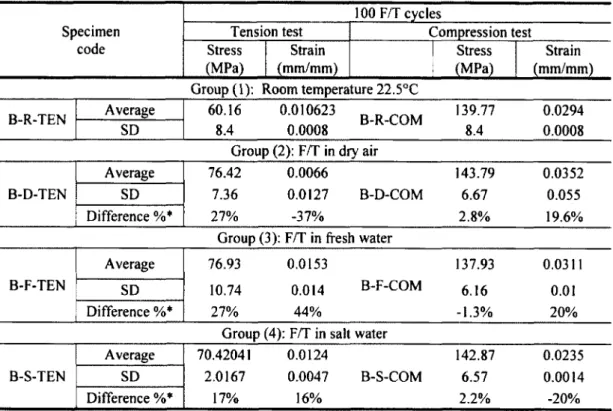
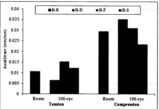
Les resultats experimentaux de compression axiale sur des cylindres en beton confines de tubes en PRFV indiquent une petite influence des cycles gel/degel sur la moyenne de la capacite ultime des cylindres confines a l’aide des tubes de type B. La reduction maximale est egale a 6.6 % apres 300 cycles dans l’eau salee. Tandis qu‘une reduction de 11.3 et 5.5 % ont ete observees dans les deformations ultimes axiale et radiale apres 100 cycles dans l’eau salee. D ’autre part, 100 cycles de gel/degel n ’avaient pas d’influence sur le comportement mecanique
des colonnes CFFT a Fexception d ’une reduction minime des capacites axiales et de la deformation ultime axiale (qui ne depassent pas 2.8% et 6.7 % respectivement dans l’eau salee). Cependant, une degradation plus importante et plus severe a ete observee dans les
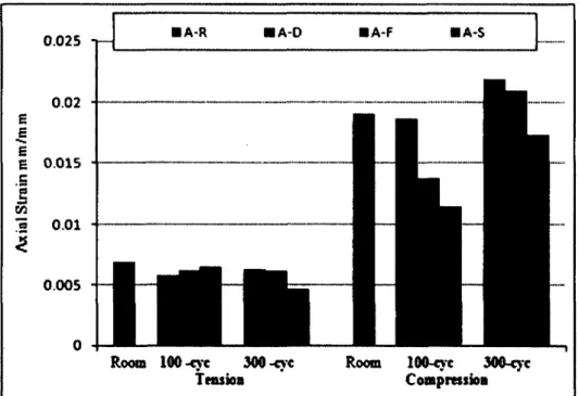
colonnes confinees a l’aide des tubes de type A en augmentant le nombre de cycles a 300 dans
l’eau pure. Des reductions de 16.2%, 42% et 21 %, respectivement, de la capacite axiale moyenne des colonnes, la deformation axiale ultime moyenne, et la deformation
circonferentielle moyenne, ont ete enregistrees.
Les etudes experimentales sur la performance des poteaux CFFT renforces indiquent que
le comportement axial sous l’effet des cycles gel/degel est influencee par les
proprietes mecaniques de chaque composante des poteaux : tube PRFV, beton et type
d ’armature interne) Les essais demontrent que l’exposition aux cycles gel-degel degradent a
differents niveaux les composantes individuelles du CFFT qui affectent le comportement a la compression des colonnes CFFT comme systeme global.
Mots-cles : axial, tubes, materiaux composites gel-degel, sale, beton arme, experimentales,
A cknowledsements
ACKNOWLEDGEMENTS
All P raise be to A llah Alm ighty and Peace be upon His P rophet M ohammed.
I would like to express my sincere and deepest g ratitu d e to my supervisor,
Prof. R adhouane M asmoudi, for his unw avering support and guidance throughout
th is research project. His patience, leadership, and never ending encouragem ent
gave me the confidence to focus and proceed. I owe him an unbelievable am ount
of g ratitu d e for his prom inent role in helping me to achieve one of th e g reatest
accom plishm ents in my life.
I would like to th a n k the stru c tu ra l laboratory technical sta ff in the
D ep artm en t of Civil E ngineering a t the U niversite de Sherbrooke, in p a rticu la r
Mr. Nicolas Sim ard for his help in my experim ental work. Special th a n k s to the
m an u factu rer (FRE Composites, S ain t'A n d re d’A rgenteuil, QC, C anada) for
providing the FRP Tubes.
Also, we are th an k fu l to The N a tu ra l Sciences and E ngineering R esearch
Council of C anada (NSERC) for supporting th is research an d to the C anadian
Foundation for Innovation (CFI) for the in frastru ctu re used to conduct testing,
which w ithout such in frastru ctu re, th is research w ork could not be possible.
M any th a n k s also go to all my colleagues and friends a t th e U niversite de
Sherbrooke. T heir friendliness stream lin ed and supported my stu d ies an d life
style d u ring th e period of my doctoral studies.
I would like to express my deep appreciation and th a n k s to my bro th ers from
th e bottom of my h e a rt for th e ir support, endless love and encouragem ent.
Especially my older b ro th er who w as th e first one ta u g h t me w riting and reading
early in my life, I g ratitu d e his advisees d u ring all my educational stage. Special
th a n k s are due my fath e r and m other, for th e ir prayers, encouragem ent and
endless love. The sp iritu a l support of all of them cannot be p raised enough.
Finally, I would like to m ark my deep love and appreciation to my hu sb an d H am dy
for his stead fast support throughout these years. He w as alw ays th ere to give me
the p ush for th is challenge. I cannot p resen t th is work w ithout expressing my love
to my son M ahm oud and my dau g h ters R azan and Lena who enlightened my life
w ith th e ir smile; to them th is th esis is dedicated.
Dedication
To ttie memory o f m yfattier wtio gooddestiny ctioose tiim tiefore
Having ttie ctiance dedicating it to tiim in tiis fife
To my mottier wtio tauytit me fa itti andaiwaysjoustiiny me forw ard
To my tirottiers wtio aiw aysgrayfor me
To my tiustiand rny son andm y dauytiters
To ttiose wtio worti tiardto matie ttie worlda tietterjaiace to five in
Table of Contents
A B ST R A C T ... i
AC K N O W LED G EM ENTS... viii
Table o f C ontents... xi
Chapter 1 Introduction...1
1.1 G eneral... 1
1.1.1 FRP Composites Potential Advantages As Construction M aterial... 2
1.1.2 FRP Composites as Innovativ and Sustainable Construction M aterial... 4
1.1.2.1 Environmental Impacts o f FRP Composites M aterials... 5
1.1.2.2 Long Term Durability...6
1.1.2.3 Life Cycle A ssessm ent...8
1.1.3 Existing Applications o f FRP Composite Materials In Architecture Engineering...8
1.1.3.1 Exteriorse applications...9
1.1.3.2 Interior Applications... 18
1.1.3.3 Complete Composite Buildings...21
1.1.4 Applications o f the GFRP tube filled with concrete as integrated innovative hybrid system in the urbaninfrastructure... 23
1.2 Objectives and O riginality... 28
1.3 M ethodology...31
Notation
Chapter 2 Freeze Thaw Cycling Effect on the Mechanical Behavior o f Filament
Wound GFRP T u b es... 36
2.1 A bstract... 36
2.2 Introduction...37
2.3 Experimental Program ... 38
2.3.1 Filament-Wound Glass FRP T u b es...38
2.3.2 Specimens Details and Preparation... 39
2.3.2.1 Freeze-Thaw Exposure... 40
2.3.2.2 Test setup and instrumentation... 42
2.3.2.2.1 Axial tension test... 42
2.3.2.2.2 Axial compression te s t...42
2.3.2.2.3 Split-disk test... 44
2.4 Results and Discussion... 47
2.4.1 Room Temperature Specimens... 47
2.4.2 Effects o f Freeze-Thaw Cycles...52
2.5 Conclusions...69
Chapter 3 Evaluation Effects o f the short and Long-Term Freeze-Thaw Exposure
on the Axial Behavior o f Concrete Filled Fiber-Reinforced-Polymer Tubes.... 71
3.1 A bstract... 71 3.2 Introduction... 72 3.3 Research Significance... 74 3.4 Experimental Program ... 75 3.4.1 Properties o f M aterials...75 3.4.1.1 FRP T u b es... 75 3.4.1.2 Concrete...75
3.4.2 Specimen details and preparation... 76
3.4.3 F reeze-Thaw Exposure...77
3.4.4 Test procedure... 80
3.5 Results and Discussion...82
3.5.1 Behavior before Testing...82
3.5.1.1 Change in Strain Level due to Freeze-Thaw C ycles... 82
3.5.2 Test Results...83
3.5.2.1 Effect o f confinement: virgin specimens...84
3.5.2.2 Effects o f freeze-thaw cycles... 87
3.5.2.2.1 Compressive strength... 87
3.5.2.2.2 Hoop and axial strain response...90
3.5.2.3 Failure m ode...95
3.6 Design and application recom m endations... 96
3.6.1 Effect o f environmental freeze-thaw cycles on plain and CFFT cylinders 98 3.6.2 Proposed Environmental Reduction Factor Based on the Experimental R esults... 100
3.6.2.1 Environmental Reduction Factor,... 101
(Dry-condition- *«"-«*)... 101
3.6.2.2 Environmental Reduction Factor,... 102
(Fresh water-condition- ^ " " -/)... 102
3.6.2.3 Environmental Reduction Factor,... 104
(Salt w a t e r - c o n d i t i o n - ) ... 104
3.6.3 Proposed Service-life Environmental Reduction Factor (75 Y ears) 105 3.6.3.1 Effect o f Confinement Using CFFT technique on the Service-life Environmental Reduction F acto r... 108
3.7 Confinement Models for Concrete Confined with FRP Tubes...109
3.7.1 Review o f Strength Models o f FRP-Confined C oncrete...110
3.7.2 Assessment o f Selected FRP-Confined M odels...113
Notation
Chapter 4 Performance Evaluation o f Reinforced Concrete Filled FRP Tubes
Columns Conditioned to Long-Term Freeze-Thaw E xp osu re... 122
4.1 A bstract... 122
4.2 Introduction and Background...123
4.3 Research Significance...127
4.4 Experimental P rogram ...127
4.4.1 M aterials... 127
4.4.1.1 Filament wound glass-FRP tu b es...127
4.4.1.2 Concrete... 129
4.4.1.3 Reinforcing steel b a rs...129
4.4.1.4 FRP Bars... 129
4.4.2 Test Specimens Details and Preparation...131
4.4.3 Freeze-Thaw E xposure... 134
4.4.4 Instrumentations and test se t-u p ... 136
4.5 Test Results and Discussion... 140
4.5.1 Results before T estin g ... 140
4.5.1.1 Change in Strain Level due to Freeze-Thaw C ycles...140
4.5.2 Test results after compression te st...142
4.5.2.1 Compressive strength...143
4.5.2.1.1 Virgin specimens...143
4.5.2.1.2 Effects o f Freeze- Thaw C ycles...148
4.5.2.2 Load-strain relationship... 152
4.5.2.2.1 Virgin specimens... 152
4.5.2.2.2 Effects o f Freeze-Thaw C ycles...156
4.5.2.3 Axial displacem ent... 162
4.5.2.3.1 Virgin specimens... 162
4.5.2.3.2 Effects o f Freeze- Thaw C ycles...166
4.5.2.4 Failure m o d es...174
4.6 Proposed Environmental Reduction Factor and Design E quations...181
4.6.1 Proposed Environmental Reduction Factor...182
4.7 Design E quations... 186
4.8 Conclusions... 192
Chapter 5 Summary and C onclusions...195
5.1 Sum m ary... 195
5.2 Conclusions... 197
5.2.1 GFRP tube mechanical properties... 197
5.2.2 CFFT cylinders...198
5.2.3 Reinforced CFFT columns... 200
Resume et C on clu sion s... 203
5.3 Resum e... 203
5.4 Conclusions...205
5.4.1 Proprietes mecaniques des tubes PRFV... 205
5.4.2 Cylindres C F F T ... 206
5.4.3 Colonnes CFFT renforcees... 208
5.5 Recommendations for Future W ork...211
Notation
List of Tables
Table Table Table Table Table Table Table Table Table Table Table Table (ACI440-2R-08)... 98Table 3-7 The Percentile change in compressive strength due to the environmental conditioning used in this study... 99
Table 3-8 Environmental Reduction Factor, (Dry-condition- 4env_d ) ... 102
Table 3-9 Environmental Reduction Factor, (Dry-condition- ) ... 102
Table 3-10 Environmental Reduction Factor, (Fresh water-condition- <t>env f ) ... 103
Table 3-11 Environmental Reduction Factor, (Fresh water -condition-
4m- , )
... 103Table 3-12 Environmental Reduction Factor, (Salt water-condition- j>env_s ) ...104
Table 3-13 Strength Reduction Factor, (Salt water -condition- 4env_s ) ...105
Table 3-14 Predicted Service-life Environmental Reduction Factor (75 years)...106
Table 3-15 Existing confining models for FRP-confined concrete... 112
Table 3-16 Performance o f selected confined models and comparison with test d a ta 115 Table 3-17 Performance o f selected confined models and comparison with test data (cont)l 16 Table 3-18 Performance o f selected confined models and comparison with test data (cont)l 17 Table 3-19 Statistical performance o f strength model for CFFT specim ens... 118
xvi 2-1 Mechanical and physical properties o f fibers and re sin ... 39
2-2 Details o f coupon tensile, compression and split-disk test specim ens... 40
2-3 Test results o f coupon tensile specimens for tube A ...53
2-4 Test results o f coupon compression specimens for tube A ...54
2-5 Test results o f coupon tensile and compression specimens for tube B ...55
2-6 Test results o f split-disk test specimens for tube A and B ...56
3-lD im ension and mechanical properties o f fiber reinforced polymer tu b e s...75
3-2 The typical number o f test units for each type o f the freeze thaw cycles...77
3-3 Test results o f unconfmed concrete cylinders...84
3-4 Overall response characteristics for confined concrete (CFFT) cylinder tube A ....85
3-5 Overall response characteristics for confined concrete (CFFT) cylinder tube B ....86 3-6 Environmental reduction factor for various FRP systems and exposure conditions
Table 4-1 Dimension imension and mechanical properties o f fiber-reinforced polymer tubes
128
Table 4-2 Properties o f reinforcing steel bars... 130
Table 4-3 Properties o f reinforcing FRP bars...131
Table 4-4 Typical number o f test specimens for each type o f the freeze thaw cycles...132
Table 4-5 Configuration and characteristics o f the tested specimens... 132
Table 4-6 The test result o f control RC columns subjected to different conditions... 143
Table 4-7 The test result o f conditioned and unconditioned CFFT columns Tube (A)... 145
Table 4-8 The test result o f conditioned and unconditioned CFFT columns Tube (B )... 146
Table 4-9 The percentile change in the compressive strength o f the conditioned and unconditioned CFFT columns compare with the control RC colum n... 151
Table 4-10 Summarize o f the percentile change in the mechanical properties due to the freeze thaw exposure used in this study relative to the room temperature exposure... 160
Table 4-11 Summary o f normalized energy absorption o f conditioned and unconditioned specim ens...164
Table 4-12 Environmental reduction factor for GFRP systems and exposure conditions (ACI440-2R-08)...182
Table 4-13 Environmental Reduction Factor, (Dry-condition-
)
...183Table 4-14Environmental Reduction Factor, (Fresh water-condition- </>eny r ) ... 184
Notation
List of Figures
Figure 1-1 The Chanel Pavilion in Central Park (Stacey 2008) 9
Figure 1-2 Honglu Clubhouse by MAD Architects (Stacey 2003) 10
Figure 1-3 The Bexhill-on-Sea Band Stand (De La Warr Pavilion 2013) 11
Figure 1-4 The reception building for the Novartis Campus Located in Basel, Switzerland
(Ernst Basler 2013). 12
Figure 1-5 The Abu Dhabi Investment Council headquarters (Composites and Architecture
2013) 13
Figure 1-6 The trellis system sits on top o f the Waikiki Shopping Plaza 14
Figure 1-7 The Eyecatcher Building (Fiberline Composites Inc 2013) 15
Figure 1-8 Multi-purpose FRP building, Weston, WV, constructed with modular FRP panels,
Nov 1995 (photo taken on Aug 27, 2009) 16
Figure 1 -9 A two-story all-FRP house (Composites and Architecture 2013) 17
Figure 1-10 Marina with composite decking (Creese and Hota 2004) 17 Figure 1-11 The pedestrian bridge in Pontresina, Switzerland (Keller 2002) 18
Figure 1-12 Charred Cedar House in Hiroshima, Japan 19
Figure 1-13 The FRP one- piece room (Dezeen magazine 2013). 20 Figure 1-14 the meeting room pods at Victoria House in London (All Design 2013) 21
Figure 1-15 FRP radome (The National Composites Network 2013) 22 Figure 1-16 The Rest Zone FRP building within the Millennium Dome, London (The National
Composites Network 2013) 22
Figure 1-17 The Home Planet Zone, a 36 m diameter FRP building (The National Composites
Network 2013) 23
Figure 2-1 Overview o f the filament wound FRP tubes 39
Figure 2-2 Conditioning the test specimens 41
Figure 2-3 Temperature variation during two complete F/T cycles 41 Figure 2-4 Dimensions and test setup for coupon tension test 43 Figure 2-5 Dimensions and test setup for coupon compression test 45
Figure 2-6 Test procedures for split-ring test. 46
Figure 2-7 Stress-strain curve for room temperature coupon tensile test 48 Figure 2-8 Dominant failure mechanisms for room temperature coupon tensile test 48
Figure 2-9 stress-strain curve o f tube A and B for room temperature coupon compression test
specimens 49
Figure 2-10 Dominant failure mechanisms coupon compression test 49
Figure 2-11 Load and hoop-strain relationship o f tube A and B for split-disk test at room
temperature condition 50
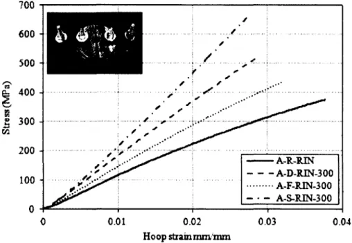
Figure 2-12 Stress and hoop-strain relationship o f tube A and B for split-disk test specimens
at room temperature condition 50
Figure 2-13 Dominant failure mechanisms o f room temperature split-disk test 51
Figure 2-14 Comparison the effect o f F/T cycles on tension and compression axial stress o f
tube A tension and compression coupons specimens 58
Figure 2-15 Comparison the effect o f F/T cycles on tension and compression axial strain o f
tube A tension and compression coupons specimens 58
Figure 2-16 Comparison the effect o f 100 F/T cycles on tension and compression stress o f tube
A tension and B o f coupons specimens. 59
Figure 2-17 Comparison the effect o f 100 F/T cycles on tension and compression axial strain
o f tube A tension and B o f coupons specimens. 59
Figure 2-18 Axial stress and axial-strain relationship o f tube A room temperature tension test compared with specimens exposed to 100 F/T cycles 60 Figure 2-19 Axial stress and axial-strain relationship o f tube A room temperature tension test
compared with specimens exposed to 300 F/T cycles 60 Figure 2-20 Axial stress and axial-strain relationship o f tube A room temperature compression
test compared with specimens exposed to 100 F/T cycles 61 Figure 2-21 Axial stress and axial-strain relationship o f tube A room temperature compression
test compared with specimens exposed to 300 F/T cycles 61 Figure 2-22 Axial stress and axial-strain relationship o f tube B room temperature compression
test compared with specimens exposed to 100 F/T cycles 62 Figure 2-23 Stress and hoop-strain relationship o f tube A room temperature split-disk test
Notation
Figure 2-24 Stress and hoop-strain relationship o f room temperature split-disk test compared
with specimens exposed to 300 F/T cycles 64
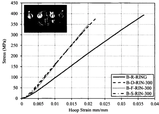
Figure 2-25 Stress and hoop-strain relationship o f tube B room temperature split-disk test
compared with specimens exposed to 100 F/T cycles 65
Figure 2-26 Stress and hoop-strain relationship o f tube B room temperature split-disk test
compared with specimens exposed to 300 F/T cycles 65
Figure 2-27 Comparison the Effect o f F/T cycles on Stress for exposed and unexposed ring
specimens 66
Figure 2-28 Comparison the Effect o f F/T cycles on hoop tensile strain for exposed and
unexposed ring specimens 66
Figure 2-29 Dominant damage mechanisms o f tube b split-disk test specimens exposed to three
different types o f freeze-thaw cycles 67
Figure 2-30 Dominant damage mechanisms o f tube A split-disk test specimens exposed to
three different types o f freeze-thaw cycles 68
Figure 3-1 Dry and Submerged specimens in the wooden tanks inside the chamber 78 Figure 3-2 Monitoring the specimens inside the chamber during the freeze-thaw cycles 79 Figure 3-3 Temperature variation o f the three conditioned sets during the F/T cycles 79
Figure 3-4 Schematic and image o f the test setup for plain concrete and CFFT cylinders 81
Figure 3-5 Strain variation during the F/T cycling 83
Figure 3-6 Signs o f degradation o f PCC at 300 F/T cycles before testing 83
Figure 3-7 typical stress strain curve o f PCC and CFFT (Tube A-B) specimens at room
temperature 89
Figure 3-8 Residual compressive stress o f Conditioned and unconditioned CFFT (tube A-B)
specimens 89
Figure 3-9 Hoop and axial strain o f conditioned and unconditioned CFFT (Tube A) 91 Figure 3-10 Hoop and axial strain o f Conditioned and unconditioned CFFT (Tube B) 92 Figure 3-11 Residual axial strain o f Conditioned and unconditioned CFFT specimens casting
in tube (A and B) 94
Figure 3-12 Residual hoop strain o f Conditioned and unconditioned CFFT specimens casting
in tube (A and B) 94
Figure 3-13 Failure modes o f conditioned and unconditioned CFFT cylinders 96
Figure 3-14 Strength reduction factor versus conditioning time for different exposure condition
107
Figure 3-15 Effect o f tube thickness on the predicted service life environmental reduction
factor (75 years) 108
Figure 4-1: Stress-axial strain relationship for coupon tensile test. 128
Figure 4-2: Load-hoop strain relationship for the split-disk test. 128
Figure 4-3 Types o f steel reinforcing bars and test set up. 130
Figure 4-4 Sand coated FRP reinforcing bars. 131
Figure 4-5 Preparation and casting o f the CFFT columns. 133
Figure 4-6 The sequences in fabricating, painting and isolating the wooden tanks 135
Figure 4-7 Isolate the specimens before undergo to submerged conditions and arrange both dry
and submerged specimens inside the chamber 135
Figure 4-8 Monitoring the specimens inside the chamber during the freeze-thaw cycles 136
Figure 4-9 temperature variation inside the three conditioned sets during 136 Figure 4-10 General arrangement o f strain gauges on the internal reinforcement 138
Figure 4-11 .Schematic and test setup Instrumentation used for CFFT columns 139
Figure 4-12 Strain variation during the F/T cycling 141
Figure 4-13 Signs o f degradation o f RC columns at 100 and at 300 F/T cycles before testing
142 Figure 4-14 The average compressive strength o f control RC and CFFT columns with diffrent
type o f both reinforcment and FRP tubes conditioned to room temperature 147
Figure 4-15 The fc c /f'c ratio o f room temperature and freeze-thaw exposed tested columns 150
Figure 4-16 The axial-load verse strains Comparison between CFFT columns casting in Tube A reinforced with steel, GFRP and CFRP bars at room temperature 155 Figure 4-17 The axial-load verse strains Comparison between CFFT columns casting Tube A
and B with and without steel reinforced at room temperature. 155 Figure 4-18 The axial-load verse strains Comparison o f the CFFT columns casting in tube A
with steel reinforcement at different type o f exposure. 158 Figure 4-19 The axial-load verse strains Comparison o f the CFFT columns casting in tube A
Notation
Figure 4-20 The axial-load verse strains Comparison o f the CFFT columns casting in tube A
with CFRP reinforcement at different type o f exposure. 159
Figure 4-21 The axial-load verse strains Comparison o f the CFFT columns casting in tube B
without any internal reinforcement at different type o f exposure. 161
Figure 4-22 The axial-load verse strains Comparison o f the CFFT columns casting in tube B
with Steel reinforcement at different type o f exposure. 161
Figure 4-23 Comparison between the axial load - axial displacement relationship o f CFFT
columns casting in tube A with steel, GFRP and CFRP internal reinforcement. 165
Figure 4-24 Comparison between the axial load - axial displacement relationship o f CFFT columns casting in tube A and B with and without internal reinforcement. 165
Figure 4-25 The normalized energy absorption o f all the CFFT test specimens relative to their
exposed control RC specimens (e c m /e c o n t). 168
Figure 4-26 Load-axial displacement behavior o f CFFT columns casting in tube A and with
steel reinforcement at different type o f exposure 169
Figure 4-27 Load-axial displacement behavior o f CFFT columns casting in tube A and with
GFRP reinforcement at different type o f exposure 169
Figure 4-28 Load-axial displacement behavior o f CFFT columns casting in tube A and with
CFRP reinforcement at different type o f exposure 170
Figure 4-29 Load-axial displacement behavior o f CFFT columns casting in tube B without
any internal reinforcement at different type o f exposure 172 Figure 4-30 Load-axial displacement behavior o f CFFT columns casting in tube B with Steel
reinforcement at different type o f exposure 172
Figure 4-31 Failure modes o f control and CFFT columns at room temperature conditioned. 177 Figure 4-32 Failure modes o f F/T conditioned (RC and CFFT) columns. 178
Figure 4-33 The failure modes o f conditioned (RC and CFFT) columns. 179 Figure 4-34 The Failure modes o f conditioned CFFT columns. 180 Figure 4-35 Experimental loads to predicted values for the conditioned CFFT columns 190
Notation
The follow ing symbols are used in this study: Ex
a
Young’s modulus in the longitudinal direction o f the FRP tubes (MPa)
Ey Young’s modulus in the hoop direction o f the FRP tubes (MPa) H Height o f the specimens (mm)
D Diameter o f the FRP tube (mm) t Thickness o f FRP tube (mm)
fe e The confined concrete compressive strength (MPa)
f ' c Concrete compressive strength (MPa)
f'c o Unconfined concrete compressive strength (MPa)
Sec Ultimate axial strain o f the confined CFFT specimens
Sch Ultimate hoop strain o f the confined CFFT specimens
sc Ultimate axial strain o f the unconfined concrete cylinders Pmsx Maximum axial load (kN)
Ag Column cross-section (internal area o f FRP tubes)
Abars Area o f reinforcing bars (steel or GFRP or CFRP)
Reduction factor o f the FRP bar as afunction o f its ultimate tensile strength f u
f fu The design tensile streangth o f the FRPs
The guaranteed tensile strength defined as the average tensile streangth o f less than three times its standard deviation.
Ce Environmental reduction factor
s/u The ultimat design tensile strain o f the FRPs
* The guaranteed tensile strain o f the FRP defined as the average
£fil tensile strain o f less than three times its standard deviation. , Environmental reduction factor for the effects o f freeze-thaw
em~d cycles in dry air
, Environmental reduction factor for the effects o f freeze-thaw cycles in fresh water
, Environmental reduction factor for the effects o f freeze-thaw
env 1 cycles in salt water
E f The elastic modulus o f the FRP tubes
The ultimate tensile strength o f the FRP tubes in the circumferential direction
The lateral confining pressure exerted by the FRP tubes on the concrete core
k x Coefficientin taken in the confined model when predicteing cylinders confined concrete strength.
N Total number o f specimens for each data set
ffu
L
f ,Notation
x i The ratio o f the experimental confined concrete compressive strength to the theoretical confined concrete compressive strength
x The average value for each data set
ADD The average absolute deviation P„ The experimental ultimate loads
Py The experimental yielding loads
Ag The column cross-section (internal area o f FRP tubes)
A bars the area o f reinforcing bars (steel or GFRP or CFRP)
P0 The nominal axial load capacity o f reinforced concrete column under concentric loading
kc Coefficientin taken when predicting The nominal axial load capacity o f reinforced concrete column under concentric loading
Chapter 1
Introduction
1.1 General
Over the long human history, structures have evolved in both their form and the materials
used to construct them. They may thus be classified into three generations based on the
technologies employed as detailed below. First-generation structures, Pre-modem structures, have been built with natural materials such as stones, bricks, timbers and bamboos. In addition to the use o f natural materials, another aspect o f these structures is
that they were in general not engineered using modem scientific principles.
Second-generation is referred to the modem steel and concrete stmctures. These structures provided the revolution needed for modem structures to cater for the infrastructure demands generated by rapid economic developments, particularly following World War II.
Steel and concrete which have been used to construct stmctures since the latter half o f the nineteenth century, still remain as the two primary construction materials today. The
second-generation is characterised by the use o f high-strength man-made materials and engineering designs based on modem scientific principles. Although the second-generation stmctures has been able to offer strength and stiffness, they suffered from many problems including deterioration far beyond that initially expected, inability to respond adaptively to extreme loadings, and irrationality and inflexibility in design methods.
Over the 20th century, many advances have been made in technologies for the design and constmction o f stmctures. Through greater safety and less cost, the essential object o f these
advances has been to enable the constmction o f stmctures o f greater spans and heights. The traditional and widespread belief had been that the stmctural engineer’s job is done once the stmcture is built with a certain assumed service life. This belief has been changed over
C h apter I: Introduction
recent decades, realising that the engineer needs to vaccinate the structure to provide
immunity from severe attacks (control), check the health o f the structure regularly
particularly when it is in its old age (monitoring), determine the cause o f any problem
(diagnosis), prescribe the necessary remedial measures (rehabilitation), and allow a longer
service life when possible (repair).
The third-generation future structures are the development o f a new integrated
technological basis which represents advances over the first and second generation in both
the materials and design methods, as well as in the additional area o f “intelligence”.
Progresses are being made around the world on a number o f fronts for the development o f this technological basis, exploiting recent technological advances in various disciplines
including material, sensor, control, information, communication and measurement
technologies, future third-generation structures may be expected to possess: (I) durable in the sense that they are highly resistant to environmental degradation over time; (II) intelligent, in the sense that they are able to continuously monitor their own state of health and activate the control devices when necessary to minimize the effects of extreme loadings (e.g. strong winds, earthquakes, fires and landslides) to ensure desirable structural performance; and (III) performance- oriented, in the sense that they are designed and constructed to satisfy specific whole-life system- level performance objectives. It may be fair to say that the researchers and engineers all over the world are challenged searching for new and affordable construction materials as well
as innovative approaches and systems to be harnessed in createing an integrated technological basis for the design and construction o f third generation structures.
1.1.1 FRP Composites Potential Advantages As Construction
Material
FRP (fibre-reinforced polymer) composites are formed by embedding continuous fibres in a resin matrix which binds the fibres together. Common fibres include carbon, glass, and
aramid fibres while common resins are epoxy, polyester, and vinyl ester resins. The most widely used FRP composites are glass FRP (GFRP) composites, carbon FRP (CFRP)
composites, and aramid FRP (AFRP) composites. FRP composites are a new generation o f structural materials for civil and architectural engineering structures. Thus they are strictly an integral part o f the technological basis which make them an important construction material
for third-generation structures. FRP Composites enjoy widespread recognition and
acceptance among engineers, designers, and builders in select industries based on the
unique combinations o f performance benefits that these materials offer. These features o f
composites translate into multiple benefits for design-builders and their ultimate customers
and users alike. By better understanding the benefits o f composites, designers, engineers,
architects, and others associated with turning design concepts into product realities can make their jobs easier and more effective.
FRP Composites are new building materials with the potential to lead to substantial innovations in bridge and building construction. For large structures such as tall buildings
and long-span bridges in any dense urban environment, composite fibre materials as an important construction material for the third-generation structures possess a number o f major
advantages. In this section, their advantages in different areas are presented which are equally available to several urban centers.
1. Offsite fabrication and modular construction
• Better quality control; • Improved health & safety;
• Faster build times;
• Manufacture can take place concurrently with ground-works on site;
• Services can be factory fitted into the structure; • Ability to automate and mechanise production. 2. Reduced mass
• Easier, faster and more economic installation - smaller cranes required; • Ability to bring larger sections to site, reducing assembly time and cost; • Less disruption during installation;
• Reduction in size and cost o f supporting structure, foundations, etc; • Reduced energy in transportation to site.
3. Superior durability
• Resistant to atmospheric degradation;
C hapter I: Introduction
4. Ability to mould complex forms
• New aesthetic possibilities;
• Geometrically more efficient solutions.
5. Special surface finishes and effects
• Ability to integrate special finishes and a very wide variety o f unusual effects;
• Simulation o f traditional materials such as stone or granite.
6. Improved thermal insulation and Lack o f cold bridging
• Reduction in carbon emissions and Running costs; • Sustainability;
• Low embedded energy;
• Possibility o f recycling;
• Possible use o f natural fibres and resins.
1.1.2 FRP Composites as Innovativ and Sustainable Construction
Material
In order to evaluate the sustainability o f FRP composites we must define a sustainable environment and how any material would comply within that defi nition. The sustainability
concept, as described in the Common Future (Lele, (1991): Sustainable development is a process o f change in which the exploitation o f resources, the direction o f investments, the orientation o f technological development, and institutional change are all in harmony and
enhance both current and future potential to meet human needs and aspirations. Sustainable development “ .. .meets the needs o f the present without compromising the ability o f future generations to meet their own needs.” When identifying appropriate metrics for
sustainability, one is likely to encounter a myriad o f proposals and ideas each potentially yielding unique results; however, in general, measures are typically centered on factors that account for the following:
1. Minimum resource use
2. Low environmental impact
3. Low human and environmental health risks
4. Sustainable site design strategies
5. Higher performance
The sustainability approach to design and construction challenges architects and engineers
to weigh environmental factors, energy/resource consumption, social factors, economic
considerations, and performance criteria. The primary benefit o f FRP composites will be
its role in solutions that seek to extend the service life o f existing structures and to develop new structures that achieve superior service life with minimal maintenance. Essentially,
efficiently maximizing the benefit o f potentially limited nonrenewable resources and
avoiding the environmental, social, and economic impacts associated with replacement and
new construction (Lee and Jain 2009).
1.1.2.1 Environmental Impacts of FRP Composites Materials
Composites materials have been identified as a versatile material for its wide variety o f applications, satisfaction o f performance requirements, and, in some cases, lowering
overall project costs. In order to evaluate the sustainability o f FRP composites, the constituent materials, namely fi ber and matrix, and manufacturing techniques must be considered. The most common polymers used as composite matrices are polyesters,
epoxies, and vinylesters. Due to the use o f fossil fuels, polymers have considerable environmental impact associated with raw materials extraction and are often the primary cause o f environmental impact, as compared to the fi bers, o f the FRP composite material (Anderson et al. 2004).
The advantageous properties o f FRP composites are well understood and evidence exists that FRP composites can be a viable materials selection toward a sustainable built infrastructure when considering direct and indirect benefits throughout a component or systems life cycle. In addition there is evidence that FRP materials can offer several
C hapter 1: Introduction
environmental advantages, namely (Halliwell 2010 ) : (1) as long as the FRP composites
exists no fossil derived C 0 2 is admitted; (2) little water is needed during manufacturing;
and (3) the lightweight o f the material minimizes the need for heavy equipment and thus
minimizing fuel consumption and emissions during construction. However, before
composite materials can be used as an alternative to conventional materials as part o f a
sustainable environment a number o f needs remain (Jain and Lee (2012):
• Development and availability o f standardized energy consumption and emissions data for
FRP composite constituent materials.
• Integration o f durability data and methods for service life prediction o f structural
members utilizing FRP composites.
• Determine appropriate strategies for end o f life to minimize waste.
• Development o f formalized methods and techniques for life cycle assessment o f structural
components and systems.
Ultimately, in order for composites to truly be considered a viable alternative, they must
be structurally and economically feasible. Currently, there are many studies regarding the structural feasibility o f composite materials. Very little quantitative research has been done
on the economic and environmental feasibility o f these materials from the perspective o f a life cycle approach.
1.1.2.2 Long Term Durability
Composite materials have been successfully developed and adapted in aerospace, automotive, industrial, electrical, military, recreational, and marine industries. However, the loading conditions, environment, and manufacturing/construction techniques for civil
infrastructure are signifi cantly different with respect to longterm performance (Karbhari et al. 2003). Furthermore, the expectation for useful service life is often 50 years or more.
The expected service life and static nature o f civil infrastructure presents a unique aspect to the issue o f durability where environmental conditions can be singular or involve a multitude o f exposures. Due to the diversity o f structures and locations, a number o f
FRP materials for sustainable construction. These environments can be categorized as follows (Liao et al. 1998; Karbhari et al. 2003):
• Moisture/solution • Alkaline environment • Thermal effects • Fatigue • Creep/relaxation • UV radiation
The diverse number o f applications and the harsh changing conditions characteristic o f the built environment make the complete durability characterization o f FRP in built
environment and urban infrastructure a challenging prospect. Over the past decades, a
number o f researchers have engaged in the investigation o f damage mechanisms and
degradation behavior o f FRP composites subject to a variety o f exposure conditions that
are singular or synergistic. Although FRP composites have been successfully used in the automotive, marine, industrial, and aerospace sectors, there are critical differences in
loading, environment, and even the types o f materials and processes used in these applications as compared to the materials-process-load combinations that are likely to be
used in civil infrastructure applications. FRP composites have also been successfully applied in pipelines, underground storage tanks, building facades, and architectural components. Anecdotal evidence provides substantial reason to believe that, if
appropriately designed and fabricated, FRP composite materials can provide longer lifetimes and lower maintenance than equivalent structures fabricated from conventional materials. However, actual data on durability is sparse, not well documented, and/or not easily accessible to the civil engineer. In addition, there is a wealth o f contradictory data
published in a variety o f venues that confuses the practicing engineer (Karbhari et al. 2003). As predictive models for the material properties o f composites become readily available,
the need to integrate available data for service life estimation and life cycle analysis will prove to be critical for accurate sustainability assessment and for comparison with other materials (Jain and Lee (2012) this was the man motivation o f this research study.
C hapter I: Introduction
1.1.2.3 Life Cycle Assessment
The life cycle assessment o f a material or structure is the sum o f all the inputs and outputs
in support o f the item from its conception and fabrication through its operation to the end
o f its useful life or “cradle-to-grave” (Woodward 1997). Whenbdetermining the
sustainability o f a material, the following items must be considered:
(1) The initial costs;
(2) The life o f the asset;
(3) The operating and maintenance costs and; (4) The disposal costs.
The initial costs o f a material or structure involves capital resources, environmental and
social impact resulting from a materials production and installation. While lower initial
costs might be attractive in the present the uses o f capital and environmental resources used and the social impact during the maintenance and replacement o f a material or structure must also be addressed. It is important to note that the selection o f FRP composites will
not be governed by the economic, environmental, and social impacts o f the material alone;
but rather, the selection o f FRP composites will be dependent on the contribution o f the material to reducing the overall life cycle costs associated with an entire structural system (Jain and Lee (2012).
1.1.3 Existing Applications of FRP Composite Materials In
Architecture Engineering
With the world facing a crisis in terms o f sustainable growth and environmental stability, the responsibility for change has fallen on to the entire engineering community. Green
building movement, science in energy and environmental design, innovation for sustainability and many other programs are poised to steer the the worled toward greener direction. Although cost has traditionally been a major impediment to composites, advances in constituent material performance, manufacturing techniques, rehabilitation methods o f in-service structures, structural optimization and rapid modular construction
have recently lowered construction costs o f composite-based infrastructure. Some o f the
FRP composites successful applicationare briefly presented below to provide the
appropriate background for the application o f FRP composites both in civil and
architectural engineering.
1.1.3.1 Exteriorse applications
Chanel Pavilion
This travelling pavilion was designed, for Chanel, by Zaha Hadid and has been first
exhibited in Hong Kong, Tokyo. From there it was packed up in 55 sea containers and shipped to Tokyo, closing there and heading to New York. Erreur ! Source du renvoi
introuvable. 1-1 shows it in New York’s Central Park. Exhibiting Chanel’s quilted bags
designed by Karl Lagerfeld. The pavilion designed to display artworks that were inspired
by Chanel’s 2.55, a quilted chain-strap handbag, the pavilion certainly oozes glamour. Its mysterious nautilus like form, which can be easily dismantled and shipped to the next city
on its global tour, reflects the keen architectural intelligence we have come to expect from its creator. FRP was selected for its formability (using hundreds o f molded fiberglass
panels mounted on a skeletal steel frame), lustrous finish and above all lightness as the pavilion needed to be transported between venues (Stacey 2008).
C hapter I: Introduction
Hongluo Club House
Hong Luo Villa district is a three-phased project. The sites for each phase are allocated
along Hong Luo Lake, reflecting the grand view o f the mountains sitting behind it. Hong
Luo Club floats on the lake, creating an easily accessible public space at the center o f the
district (see Figure 1-2). The architects o f Hongluo Clubhouse, Ma Yansong and Yosuke
Hayano o f MAD intend ‘the structure appear to ascend from the lake itself. A continuous,
reflective surface rises up out o f the water, becoming first the roof and then the walls o f
the clubhouse. This surface blurs the distinction between solid and liquid states, between building and environment.’ Framework o f curved steel sections was used to build the roof
o f this house, which was clad on site with plywood. The plywood was coated on site with
glass fibre reinforced epoxy resin, exploiting the inherent flexibility o f GRP. The outer
surface was painted silver. The design intent o f this project is a tectonic, the role o f the
flowing folded roof surface is to define space and provide reflectance. The materials are not used in an expressive manner. Here we see FRP as a rival to the formability o f concrete and this challenge has been extended by the invention o f high performance concretes
(Stacey 2003).
Figure 1-2 Honglu Clubhouse by MAD Architects (Stacey 2003)
Bexhill-on-Sea Band Stand
Bexhill-on-Sea Band Stand by Niall McLaughlin Architects from 2002 shown in Figure 1-3 is an example o f a FRP skinned structure. The bandstand's design evolved from concepts developed by the children, in collaboration with the architects and architecture students, during a series o f workshops held at the Pavilion. The Bandstand's shell-like
seafront location. The simple white finish and ultra modem steel, plywood & fibreglass
constmction o f the bandstand, are a perfectly compliment to the modernist aesthetics and
innovative constmction techniques o f the De La Warr Pavilion. The bandstand itself is movable, allowing it to be relocated to different areas o f the terrace according to the season,
or in order to accommodate the varying needs o f performances. Producing a design for the
bandstand, that was both elegant and ergonomic, had always been a major consideration.
Therefore, throughout the project, a number o f potential bandstand users including Battle
Town Band, were consulted in order to ensure that the design could accommodate widest
possible range o f uses. The new De La Warr Pavilion Bandstand won awards from the Royal Institute o f British Architecture (RIBA) and The Royal Institute o f Australian
Architects (RIAI). The jury said that: The form is exhilarating, recalling both the dynamics
o f early modernism and the organic aspirations o f the present day. Architect and client have worked together with an admirable clarity o f thought to achieve excellent results (De La
Warr Pavilion 2013).
Figure 1-3 The Bexhill-on-Sea Band Stand (De La Warr Pavilion 2013)
Novartis Campus
The reception building for the Novartis Campus Located in Basel, Switzerland is a load- bearing constmction consisting completely o f glass. The design o f the architect, Marco Serrain 2007, called for a high degree o f transparency and what appears to be a floating roof. It has a wing-shaped roof made from glass fibre reinforced plastic (see Figure 1-4).
The load-bearing fa
9
ade, which consists solely o f glass elements, makes it possible to do without any additional supporting stmctures between the floor and the roof. The roof is aC hapter I: Introduction
functions, for example the supporting function, thermal insulation and waterproofing, in a
single, seamless element. Keller, Hass and Vallee note that: “The roof must be lightweight due to the limited load-carrying capacity o f the glass walls and, at the same time, it must
provide thermal insulation and waterproofing for the building. Consideration o f the
complex double-curved geometry led to the use o f a GFRP sandwich structure o f variable
depth” the static and constructive form o f the roof and fa?ade takes into account the
manufacturing sequences, complex geometry and different behaviour o f the materials used.
The large, self-propelled swing doors fulfil numerous requirements for operation, safety,
security and structural physics (Keller 2008, Ernst Basler 2013).
4 ie "
Figure l -4 The reception building for the Novartis Campus Located in Basel, Switzerland (Ernst Basler 2013).
Al Bahr Towers
The Al Bahr Towers, 29 story-towers, were designed by the international design firm, Aedas Architecture.Two meters outside the building wall, and there is a screen that wraps
around the east-, south-, and west-facing sections o f each tower. It is composed o f hundreds o f articulated triangular FRP-clad panels arranged in hexagonal “flowers.” The entire panel system is supported on a steel frame independent o f the building. The orientation o f each panel is fully adjustable, and they are controlled by computer. The programming responds to light conditions, and adjusts the position o f each panel to provide shade from the correct
screen wall recalls a mashrabiya, an element o f traditional Arabic architecture dating back
centuries. The responsive fasade is not only constantly changing throughout the day, but
will present a varying “texture” throughout the year as the sun’s altitude in the sky changes
with the seasons. The shielding action makes the building far more sustainable (see Figure
1-5). It is estimated to reduce solar heat gain by 50%, allowing a major reduction in energy
consumption for air conditioning.
It also enabled the designers to select glazing with a fairly light tint, allowing more daylight
to enter, reducing the need for artificial lighting, and giving occupants a more naturally-
tinted view o f the outside world. The towers have solar (photovoltaic) panels on the roof which supply power for, among other things, controlling the position o f the mashrabiya
panels. The selection o f FRP to take all this heat is interesting. Polymers are often thought
o f as heat-sensitive, but this application clearly shows that they can withstand some o f the most demanding climate conditions that our planet has to offer (Composites and
Architecture 2013).
Figure 1-5 The Abu Dhabi Investment Council headquarters (Composites and Architecture 2013)