This reproduction is the best copy available.
Faculte de genie Departement de genie civil
BEHAVIOR OF CIRCULAR CONCRETE
COLUMNS REINFORCED WITH FRP BARS AND
STIRRUPS
Comportement de colonnes circulaires en beton arme de barres et de cadres
de PRF
These de doctorat Specialite: genie civil
M oham m ad M . Z ak i M . A fifi
A dissertation submitted in partial fulfillment o f the requirements for the degree o f
Doctor o f Philosophy (Civil Engineering)
Jury: Prof. Brahim BENMOKRANE (directeur de recherche) Prof. Amir FAM
Prof. Amr EL RAGABY Prof. Nathalie ROY
1+1
Published Heritage Branch Direction du Patrimoine de I'edition 395 Wellington Street Ottawa ON K 1A0N 4 Canada 395, rue Wellington Ottawa ON K1A 0N4 CanadaYour file Votre reference ISBN: 978-0-499-00421-5 Our file Notre reference ISBN: 978-0-499-00421-5
NOTICE:
The author has granted a non
exclusive license allowing Library and Archives Canada to reproduce, publish, archive, preserve, conserve, communicate to the public by
telecomm unication or on the Internet, loan, distrbute and sell theses
worldwide, for commercial or non commercial purposes, in microform, paper, electronic and/or any other formats.
AVIS:
L'auteur a accorde une licence non exclusive permettant a la Bibliotheque et Archives Canada de reproduire, publier, archiver, sauvegarder, conserver, transmettre au public par telecomm unication ou par I'lnternet, preter, distribuer et vendre des theses partout dans le monde, a des fins com merciales ou autres, sur support microforme, papier, electronique et/ou autres formats.
The author retains copyright ownership and moral rights in this thesis. Neither the thesis nor substantial extracts from it may be printed or otherwise reproduced without the author's permission.
L'auteur conserve la propriete du droit d'auteur et des droits moraux qui protege cette these. Ni la these ni des extraits substantiels de celle-ci ne doivent etre imprimes ou autrement
reproduits sans son autorisation.
In compliance with the Canadian Privacy A ct some supporting forms may have been removed from this thesis.
W hile these forms may be included in the document page count, their removal does not represent any loss of content from the thesis.
Conform em ent a la loi canadienne sur la protection de la vie privee, quelques
form ulaires secondaires ont ete enleves de cette these.
Bien que ces form ulaires aient inclus dans la pagination, il n'y aura aucun contenu manquant.
ABSTRACT
The behavior o f concrete members reinforced with fiber reinforced polymer (FRP) bars has been the focus o f many studies in recent years. Nowadays, several codes and design guidelines are available for the design o f concrete structures reinforced with FRP bars under flexural and shear loads. Meanwhile, limited research work has been conducted to examine the axial behavior o f reinforced concrete (RC) columns with FRP bars. Due to a lack o f research investigating the axial behavior o f FRP reinforced concrete columns, North American codes and design guidelines do not recommend using FRP bars as longitudinal reinforcement in columns to resist compressive stresses.
This dissertation aims at evaluating the axial performance o f RC compression members reinforced with glass FRP (GFRP) and carbon FRP (CFRP) bars and stirrups through experimental and analytical investigations. A total o f twenty seven full scale circular RC specimens were fabricated and tested experimentally under concentric axial load. The 300 mm diameter columns were designed according to CAN/CSA S806-12 code requirements. The specimens were divided to three series; series I contains three reference columns; one plain concrete and 2 specimens reinforced with steel reinforcement. Series II contains 12 specimens internally reinforced with GFRP longitudinal bars and transverse GFRP stirrups, while series III includes specimens totally reinforced with CFRP reinforcement. The experimental tests were performed at the structural laboratory, Faculty o f Engineering, University o f Sherbrooke. The main objective o f testing these specimens is to investigate the behavior o f circular concrete columns reinforced with GFRP or CFRP longitudinal bars and transverse hoops or spirals reinforcement. Several parameters have been studied; type o f reinforcement, longitudinal reinforcement ratio, the volumetric ratios, diameters, and spacing of spiral reinforcement, confinement configuration (spirals versus hoops), and lap length o f hoops. The test results o f the tested columns were presented and discussed in terms o f axial load capacity, mode o f failure, concrete, longitudinal, and transverse strains, ductility, load/stress-strain response, and concrete confinement strength through four journal papers presented in this dissertation.
Based on the findings o f experimental investigation, the GFRP and CFRP RC columns behaved similar to the columns reinforced with steel. It was found that, FRP bars were effective in resisting compression until after crushing o f concrete, and contributed on average 8% and 13% o f column capacity for GFRP and CFRP RC specimens, respectively. Also, the use o f GFRP and CFRP spirals or hoops according to the provisions o f CSA S806-12 yielded sufficient restraint against the buckling o f the longitudinal FRP bars and provided good confinement o f the concrete core in the post peak stages. The axial deformability (ductility) and confinement efficiency can be better improved by using small FRP spirals with closer spacing rather than larger diameters with greater spacing. It was found that, ignoring the contribution o f FRP longitudinal bars in the CAN/CSA S806-12 design equation underestimated the maximum capacity o f the tested specimens. Based on this finding, the design equation is modified to accurately predict the ultimate load capacities o f FRP RC columns. New factors a g and a c were introduced in the modified equation to account for the GFRP and CFRP bars compressive strength properties as a function in their ultimate tensile strength.
On the other hand, proposed equations and confinement model were presented to predict the axial stress-strain behavior o f FRP RC columns confined by FRP spirals or hoops. The model takes into account the effect o f many parameters such as; type o f reinforcement, longitudinal reinforcement ratio; transverse reinforcement configuration; and the volumetric ratio. The proposed model can be used to evaluate the confining pressure, confined concrete core stress, corresponding concrete strain, and stress-strain relationship. The results o f analysis using the proposed confinement model were compared with experimental database o f tw enty four full-scale circular FRP RC columns. A good agreement has been obtained between the analytical and experimental results. Proposed equations to predict both strength and stress-strain behavior o f confined columns by FRP reinforcements demonstrate good correlation with test data obtained from full-scale specimens.
BIBLIOGRAPHY
During the research work at the University o f Sherbrooke, the candidate has participated in the following publications related papers and reports that have been published:
Journal Papers
1. Afifi, M., Mohamed H., and Benmokrane, B., 2013, “Theoretical Stress—Strain Model for Circular Concrete Columns Confined by GFRP Spirals and Hoops”,
AC I Structural Journal. Subm itted November 2013 (S -2013-386).
2. Afifi, M ., Mohamed H., and Benmokrane, B., 2012, “Strength and Axial Behavior o f Circular Concrete Columns Reinforced with CFRP Bars and Spirals”,
Journal o f Composites fo r Construction, ACSE. P ublished online October 2013
(10.1061 /(ASCE)CC. 1943 -5614.0000430).
3. Afifi, M ., Mohamed H., and Benmokrane, B., 2013, “Axial Capacity o f Circular Concrete Columns Reinforced with GFRP Bars and Spirals”, Journal o f
Composites fo r Construction, ACSE. P ublished online September 2013
(10.1061 /(ASCE)CC. 1943 -5614.000043 8).
4. Mohamed H., Afifi, M., and Benmokrane, B., 2012, “Performance Evaluation o f Concrete Columns Reinforced Longitudinally with FRP Bars and Confined with FRP Hoops and Spirals under Axial Load”, Journal o f Bridge Engineering, ASCE. Accepted December 2013 (MS BEENG-1428R3).
5. Afifi, M ., Mohamed H., and Benmokrane, B., 2013, “Confinement Model for Circular Concrete Columns Reinforced with CFRP Longitudinal Bars and Transverse Spirals or Hoops”, Journal o f Engineering Structures, (to be submitted January 2014).
Refereed Conferences Publications
6. Afifi, M ., Mohamed H.M, and Benmokrane, B., 2013, “Axial Load Capacity o f Circular Concrete Columns Reinforced with FRP Bars and Stirrups”, 11th International Symposium on Fiber Reinforced Polymers for Reinforced Concrete Structures Conference, FRPRCS, Guimaraes, Portugal, 26-28 June 2013.
7. Afifi, M., Mohamed H.M, and Benmokrane, B., 2013, “Behavior o f Circular Concrete Columns Internally Reinforced w ith CFRP Bars and Spiral Stirrups” , 3rd Specialty Conference on Engineering Mechanics and Materials, CSCE Annual Conference, 29 May- 1 June 2013.
Posters:
8. Afifi, M., Mohamed H.M, and Benmokrane, B., 2012, “Behavior o f Full-Scale Circular Concrete Columns Reinforced with Glass Fibre Reinforced Polymer under Concentric and Eccentric Loads”, CRIB conference, Sherbrooke, Canada, May 2012.
9. Afifi, M., Mohamed, H., Benmokrane, B., 2011, “Behavior o f Circular Concrete Columns Reinforced with FRP Bars and Stirrups”, CRIB conference, Montreal, Canada, June 2011.
Also, the candidate has participated in the following related papers and reports that have been published:
Refereed Conference Publications:
10. Mohamed H.M, Afifi, M ., and Benmokrane, B., 2012, “New Developed FRP- Headed Rebars for Infrastructure Applications”, 3rd International Structural Specialty Conference, Edmonton, Alberta, Canada, June 6-9, 2012.
Technical Reports
11. Afifi, M., Mohamed H.M, and Benmokrane, B., 2013, “Behavior o f Circular Concrete Columns Reinforced with CFRP Bars and spirals”, M EDIE Annual Report, February 2013.
12. Afifi, M., Mohamed H.M, and Benmokrane, B., 2012, “Behavior o f Circular Concrete Columns Reinforced with GFRP Bars and Spirals”, M EDIE Annual Report, February 2012.
13. Afifi, M., Mohamed H.M, and Benmokrane, B., 2012, “Behavior o f Circular Concrete Columns Reinforced with FRP Bars and Stirrups”, NSERC Annual Report, January 2012.
RESUME
Le comportement des elements en beton arme de barres en polymeres renforces de fibres (FRP) a fait l’objet de nombreuses etudes au cours des demieres annees. A date, plusieurs codes et guides de design sont disponibles pour la conception de structures en beton arme de barres en PRF sous des charges de flexion et de cisaillement. Cependant, peu de travaux de recherche ont ete menes pour examiner le comportement axial des colonnes en beton renforcees avec des barres en PRF. En raison d'un manque de recherche portant sur le comportement axial des colonnes en beton arme renforcees de PRF, les codes nord- americains et les guides de conception ne recommandent pas l'utilisation de barres en PRF comme armature longitudinale dans les colonnes pour resister a des contraintes de compression.
Cette these vise a evaluer la performance axiale des elements en compression renforces de barres et des etriers en PRFV et PRFC a travers des etudes experimentales et analytiques. Ainsi, deux types d’etriers (armature transversale) en fibre de verre (PRFV) et en fibre de carbone (PRFC), le premier constitue d ’un cadre circulaire et l’autre d ’un cadre circulaire continu (spirale continue de forme circulaire) ont ete utilises. Vingt-sept colonnes circulaires a grande echelle ont ete fabriquees et testees experimentalement sous charge axiale concentrique. Les colonnes de 300 mm de diametre ont ete con?ues selon la norme CAN / CSA S806 - 12. Les echantillons ont ete divises en trois series : la serie I contient trois colonnes de reference, l’une fabriquee avec un beton ordinaire et 2 colonnes renforcees avec de l’armature en acier. La serie II contient 12 specimens renforces interieurement avec des barres longitudinales en PRFV et des cadres en PRFV, tandis que la serie III comprend des specimens entierement renforces avec des barres en PRFC. Les essais experimentaux ont ete realises au laboratoire de structure, de la Faculte de genie, de l’Universite de Sherbrooke. L'objectif principal de ces essais est d'etudier le comportement des colonnes circulaires en beton renforcees de barres longitudinales et transversales et des etriers en spirales en PRFV ou PRFC. Plusieurs parametres ont ete etudies ; type d ’armature, taux d'armature longitudinale, les pourcentages volumetriques, les diametres et l'espacement de 1'armature transversale, la configuration de confinement (spirales contre etriers) et la longueur de recouvrement des cerceaux. Les resultats des
essais des colonnes testees ont ete presentes et discutes en termes de capacite axiale, de mode de rupture, de deformations longitudinale et transversale, de ductilite, de la reponse charge/contrainte-deformation, et de la resistance de confinement du beton a travers quatre articles de joum aux presentes dans cette these
Sur la base des conclusions des essais experimentaux, les colonnes en PRFV et en PRFC ont eu un comportement simiiaire aux colonnes renforcees avec de l’acier. II a ete constate que les barres en PRF ont ete efficaces pour resister a la compression, et ont contribue en moyenne de 8% et 13% de la capacite des colonnes en PRFV et PRFC, respectivement. Aussi, l'utilisation de spirales en PRFV et PRFC, conformement aux dispositions de la norme CSA S806 -12 a donne suffisamment de resistance contre le flambage des barres longitudinales en PRF et a foumi un bon confinement du noyau de beton dans les phases post-pic. La deformabilite axiale (ductilite) et l'efficacite du confinement peuvent etre ameliorees par une meilleure utilisation de petites spirales en PRF avec un espacement plus rapproche plutot que de grands diametres avec un plus grand espacement. On a constate qu’en ignorant la contribution des barres longitudinales en PRF dans l’equation de design de la norme S806 -12 du code CSA, on sous-estime la capacite maximale des echantillons testes. L'equation de design est modifiee pour predire avec precision les capacites de charge ultimes de colonnes en PRF. De nouveaux coefficients a g et a c ont ete introduits dans l'equation modifiee pour tenir compte des proprietes de resistance a la compression des barres en PRFC comme une fonction de leur resistance a la traction.
D'autre part, des equations et un modele de confinement ont proposes pour predire le comportement contrainte-deformation axiale de colonnes confinees par cadre circulaire ou cadre circulaire continu (spirale continue de forme circulaire) de PRF. Le modele prend en compte l'effet de plusieurs parametres, tels que: le type d ’armature, le pourcentage d'armature longitudinale; la configuration de l’armature transversale, et le pourcentage volumetrique. Le modele propose peut etre utilise pour evaluer la pression de confinement, la contrainte du noyau de beton confine et la relation contrainte- deformation. Les resultats de l’analyse selon le modele de confinement envisage ont ete compares aux donnees experimentales des vingt-quatre colonnes circulaires a grande
echelle en PRF. Une bonne concordance a ete obtenue entre les resultats analytiques et experimentaux. Les equations proposees pour predire a la fois la resistance et le comportement contrainte-deformation de colonnes confinees par des armatures en PRF montrent une bonne correlation avec les donnees des essais obtenues a partir d’echantilions a grande echelle.
ACKNOWLEDGEMENTS
I wish to take the opportunity to express my acknowledgements to those whom without their assistance this dissertation work could not have been done.
1 would like to express my sincere greatest appreciation and thanks to my supervisor Professor Brahim Benmokrane for offering me the opportunity to work on such a challenging subject. I am so proud to work with him. All o f the guidance, insight, helpful advice, and constant encouragement provided throughout the course o f the dissertation are greatly appreciated. I owe him an unbelievable amount o f gratitude for his prominent role in helping me to achieve one o f the greatest accomplishments in my life.
I am deeply grateful indebted to Dr. Hamdy Mohamed for his constant cooperation, continuous encouragement, consulting, guidance, and friendship not only on the academic side but also on the personal level. He helped me in overcoming obstacles that I encountered during my first year in Canada.
1 would like to thank the structural laboratory technical staff at the Structures Laboratory, Department of Civil Engineering at the Universite de Sherbrooke, especially, Mr. Francois Ntacorigira, Simon Kelly, and Martin Bernard for their technical assistance during the fabrication, construction and testing o f the specimens.
Also, we are thankful to Natural Science and Engineering Research Council o f Canada (NSERC) and the Fonds quebecois de la recherche sur la nature et les technologies (FQRNT) for their financial support; Pultrall Inc. (Thetford Mines, Quebec) for their donation o f the FRP materials, and the University o f Sherbrooke is greatly acknowledged for supporting this research.
Many thanks also go to all my colleagues and friends at the Universite de Sherbrooke. Their friendliness streamlined and supported my studies and life style during the period o f my doctoral studies.
I cannot end my acknowledgements without expressing my deep appreciation and thanks to: my father, my mother, my brother and sisters from the bottom o f my heart for their support, endless love and encouragement. Special thanks are due my father and mother, for their prayers, encouragement and endless love. The spiritual support o f all o f them cannot be praised enough. Finally, I owe my loving thanks and deep love and appreciation to my wife for her steadfast support and continuously encouraged me throughout these years. She was always there to give me the push for this challenge. I cannot present this work without expressing my love to my son Y oussuf who enlightened my life with his smile.
DEDICATION
To the researchers and engineers who appreciate the value o f science anct
knowledge.
To my beloved parents who have forward me over themselves and given
me all what they could. 'My LordI Bestow on them your mercy as they
did bring me up when i was young'
To my brother and sisters whom always give their patience, support,
encouragement, and extensive supports at important times o f my life.
To my lovely wife who always supports me and understands my special
circumstances as a researcher.
To my son Youssuf who come to the existence during my doctorate and
has made a big difference to my life.
TABLE OF CONTENTS
A B S T R A C T ...i B IB LIO G R A P H Y ... iii R E S U M E ...v A C K N O W LE D G E M E N TS...viii TA B LE O F C O N T E N T S ...x L IS T O F F IG U R E S... xix L IS T O F T A B L E S ... XXV N O T A T IO N S ... xxviiCHAPTER 1 INTRODUCTION... 1
1.1 • Back Ground and Problem D efinition... 1
1.2 Research Significance...3
1.3 Research O bjectives...4
1.4 M ethodology...4
1.5 Structure of the Dissertation... 5
CHAPTER 2 LITERATURE R E V IE W ...8
2.1 Introduction... 8
2.3 Fibre Reinforced Polymer Composite M aterial...9
2.3.1 Mechanical'Properties o f FRP Reinforcing B ars...11
2.3.1.1 Axial Tensile Strength...11
2.3.1.2 Compressive Strength... 14
2.3.1.3 Shear Strength... 15
2.3.1.4 Bond Strength (Pull-out Test)... 15
2.3.1.5 Bend Portion S tren g th ... 16
2.4 Confinement o f Concrete C olum ns... 19
2.4.1 External Confinem ent... 20
2.4.1.1 Concrete Filled Steel Tubes...21
2.4.1.2 Concrete Filled FRP Tubes (C F F T )...22
2.4.2 Internal C onfinem ent...23
2.4.2.1 Confinement using Steel R einforcem ent... 24
2.4.2.2 Confinement using FRP Reinforcem ent... 26
2.5 Factors Influencing the Column Bearing C ap acity ...26
2.5.1 Longitudinal Reinforcement Ratio ( pst )...27
2.5.2 Horizontal Reinforcement Ratio ( p s ) ... 30
2.5.3 Column Size...36
2.5.5 Concrete Strength...40
2.5.6 Lateral Reinforcement Yield Strength...42
2.6 Numerical Confinement Modeling o f Circular Reinforced Concrete C olum ns. ... 43
2.6.1 Numerical Confinement M odels... 43
2.6.2 Empirical Confinement M odels... 45
2.7 Design Codes Requirements on Capacity in RC Columns...47
2.7.1 Concrete Columns Reinforced with Steel B a rs ... 47
2.7.1.1 ACI 318-11 Building C ode... 48
2.7.1.2 CAN/CSA A23.3-04 Canadian C o d e ...49
2.7.1.3 Canadian Highway Bridge Design Code CAN/CSA S6-06... 50
2.7.2 Concrete Columns Reinforced with FRP B a rs ...51
2.7.2.1 ACI 440.1 R.06 Design G uide... 51
2.7.2.2 Canadian Highway Bridge Design Code CSA S 6 -0 6 ...52
2.7.2.3 CAN/CSA S806-12 Canadian C ode... 52
CHAPTER 3 RESEARCH PROG RAM
...533.1 General... 53
3.2 Experimental Research P ro g ram ...53
3.2.2 Material Properties... 54
3.2.2.1 Plain Concrete... 54
3.2.2.2 Steel R einforcem ent...54
3.2.2.3 GFRP R einforcem ent... 54
3.2.2.4 CFRP Reinforcement...57
3.2.3 Test Matrix, Parameters and Specimens Details... 59
3.2.3.1 Series I Specimens’ D etails...60
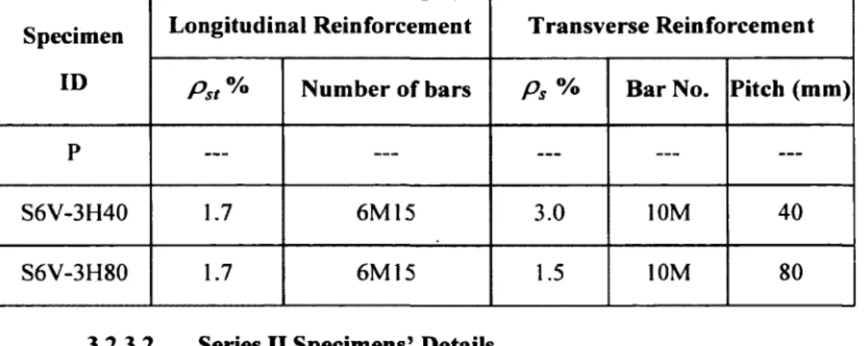
3.2.3.2 Series II Specimens’ D etails...61
3.2.3.3 Series III Specimens’ D e ta ils ... 63
3.2.4 Fabrication o f the Test Specim ens... 65
3.2.5 Instrumentations and Test Setup...69
3.3 Analytical Research Program ...72
CHAPTER
4 AXIAL CAPACITY O F CIRCULAR CONCRETE
COLUMNS REINFORCED
WITH GFRP
BARS AND
SPIRAL
STIRRUPS
...734.1 Preface... 73
4.1.1 Authors and affiliation... 73
4.1.2 French titre:...74
4.1.4 French abstract:... 74 4.2 Abstract... 75 4.3 Introduction... 76 4.4 Previous Research... 77 4.5 O bjectives... 79 4.6 Experimental Program ...79 4.6.1 Material Properties... 80
4.6.2 Test Matrix and Specimen Preparation... 82
4.6.3 Instrumentation and Test S e tu p ... 87
4.7 Experimental Results and Discussion...88
4.7.1 General Behavior and Failure M o d es... 88
4.7.2 Effect o f Test Variables on the Behavior o f GFRP RC Columns...97
4.7.2.1 Reinforcement T y p e ... 99
4.7.2.2 Longitudinal GFRP Reinforcement R atio ...101
4.7.2.3 GFRP Spiral Spacing... 102
4.7.2.4 GFRP Spiral Size...105
4.7.2.5 GFRP Spiral Size/Spacing C onfiguration...106
4.8 Ultimate Capacity and Design Equations...108
CHAPTER 5 STRENGTH AND AXIAL BEHAVIOR OF CIRCULAR
CONCRETE COLUMNS REINFORCED WITH CFRP BARS AND
SPIRALS
...1125.1 Preface...112
5.1.1 Authors and affiliation... 112
5.1.2 French titre:...113
5.1.3 Contribution in thesis:... 113
5.1.4 French abstract:... 113
5.2 Abstract...114
5.3 Introduction and B ackground... 114
5.4 O bjectives...117
5.5 Experimental Investigation... 117
5.5.1 Material Properties... 118
5.5.2 Specimen D esig n... 119
5.5.3 Instrumentation and Testing Procedure...124
5.6 Experimental Results and Discussion...126
5.6.1 General Behavior and Failure M o d es... 126
5.6.2 Effect o f Test Variables on the Behavior o f CFRP RC Colum ns...136
5.6.2.2 Longitudinal CFRP Reinforcement R a tio ...139
5.6.2.3 CFRP Spiral Spacing... 139
5.6.2.4 CFRP Spiral S ize... 142
5.6.2.5 CFRP Spiral Size/Spacing Configuration...142
5.7 Predicted Versus Measured Load Carrying Capacity... 144
5.8 C onclusions... 147
CHAPTER
6
THEORETICAL
STRESS-STRAIN MODEL
FOR
CIRCULAR CONCRETE COLUMNS CONFINED B Y FRP SPIRALS
AND HOOPS
... 1496.1 Preface... 149
6.1.1 Authors and affiliation... 149
6.1.2 French titre:...150 6.1.3 Contribution in thesis:... 150 6.1.4 French abstract:... 150 6.2 Abstract...152 6.3 Introduction... 153 6.4 Research Significance... 154 6.5 Experimental D atabase... 155
6.6.1 Failure and Strength B ehavior... 160
6.6.2 Dilation and Volumetric Stress-Strain Response...167
6.7 Confinement M odeling... 172
6.7.1 Proposed Confinement Model for Circular Concrete Columns Confined with FRP Spirals and H oops... 177
6.7.2 Modified Mander et al.’s M o d el... 183
6.7.3 Development o f Stress-Strain Relationship for FRP-RC Circular C olum ns.. 188 6.7.3.1 Ascending Branch (Pre-Peak Z o n e )... 190
6.7.3.2 Descending Branch (Pre-Peak Z o n e )...192
6.8 Concluding R em arks...196
CHAPTER 7 SUMMARY, CONCLUSIONS, AN D RECOMMENDATION
FOR FUTURE WORK
...1987.1 Summary... 198
7.2 C onclusions...199
7.2.1 Type o f reinforcement...199
7.2.2 Longitudinal reinforcement ra tio ...200
7.2.3 Spiral S ize...200
7.2.4 Spiral Pitch...200
7.2.6 Stirrup configuration... 201
7.2.7 Hoops overlap length... 202
7.2.8 Confinement model... 202
7.3 Recommendations for Future W o rk ... 203
A N N E X A ... 210 R E F E R E N C E S ... 227
LIST OF FIGURES
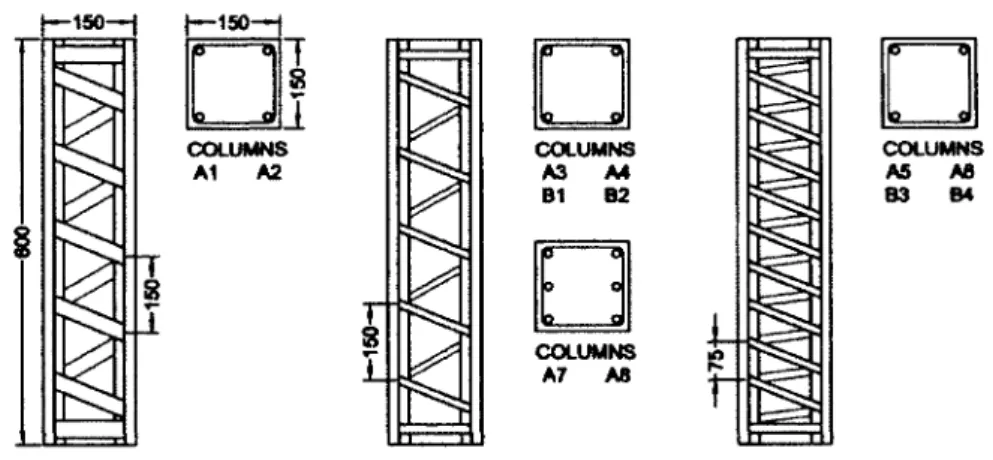
Figure 2-1: Plain concrete stress-strain diagrams (Carreira and Chu 1985)... 9 Figure 2-2: Basic material components o f FRP com posite... 10 Figure 2-3: Anchor length according to A ST M D7205/D7205M-06 (2006)...12 Figure 2-4: Schematic drawing o f pull-out test (B.3) ... 16 Figure 2-5: Schematic drawing fo r B.5 test (Ahmed et al. 2 0 1 0 )...18 Figure 2-6: Effect o f lateral confining pressure on stress-strain response (Richart et al. 1928)... 20 Figure 2-7: Schematic fo r concrete-filled tubes...21 Figure 2-8: Load-displacement behavior fo r RC and GFRP-confined concrete (Mohamed and Masmoudi 2 0 1 0 )... 23 Figure 2-9: Steel cage assembly...24 Figure 2-10: Stress-strain model (Mander et al. 19 8 8 )... 25 Figure 2-11: Effect o f longitudinal reinforcement on ductility (Bjerkeli et al. 1990)...27 Figure 2-12: Center line moment versus compressive strain (Xie et al. 1997)... 28 Figure 2-13: Effect o f amount o f longitudinal reinforcement (Sharma et al. 2005)... 29 Figure 2-14: Effect o f amount o f lateral steel (Sheikh and Toklucu 1993)...31 Figure 2-15: Aram idfibre stirrups (Leung and Burgoyne 2 0 0 1 )... 32 Figure 2-16: Effect o f volumetric ratio and spacing o f lateral reinforcement (Sharma et al. 2005)... 33
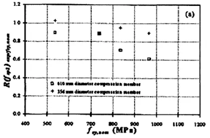
Figure 2-17: Reinforcement details fo r specimens (De Luca et al. 20 10 )...34 Figure 2-18: Nominal dimensions and reinforcement retails (Francis and Teng 2010) . 35 Figure 2-19: Reinforcement cage assembly (Francis and Teng 2010)... 35 Figure 2-20: Stress-strain relationship fo r tested specimens (Francis and Teng 2010) . 35 Figure 2-21: Effect o f specimen size (Sheikh and Toklucu 1993)... 37 Figure 2-22: Comparison between 356 mm and 610 mm diameters (Pessiki et al. 2001)
... 37
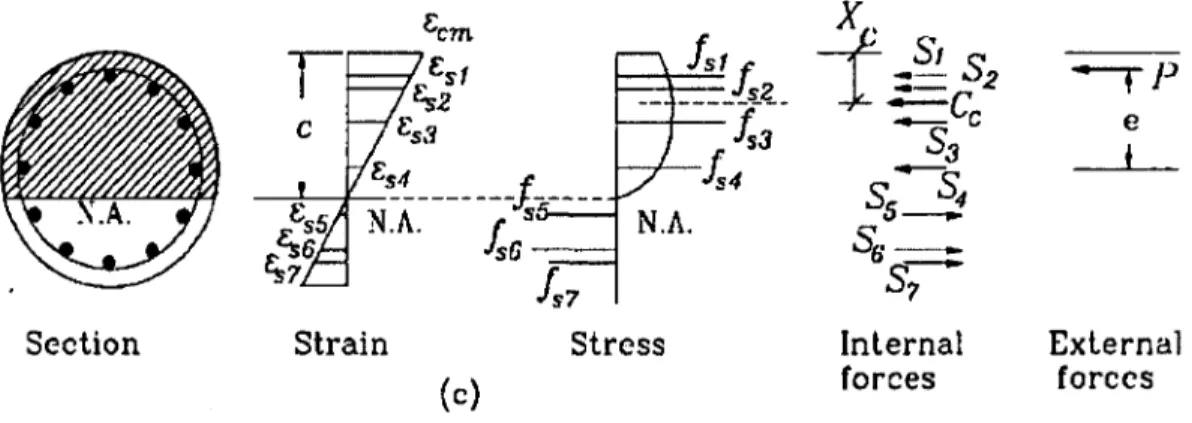
Figure 2-23: Theoretical moment-curvature analysis: section with strain, stress, and force distribution (Samra et al. 1996)... 38
Figure 2-24: GFRP reinforcement cage with carbon fibre spiral placed in form w ork (Tikka et al. 2010)...39 Figure 2-25: Dimensions and specimens reinforcement details (Tikka et al. 2010)... 40 Figure 2-26: Effect o f concrete strength on strength and deformability o f confined concrete (Razvi and Saatcioglu 1999)... 41 Figure 2-27: Specimens with normal yield strength confining reinforcement after testing (Bing et al. 2 0 0 1 )...42 Figure 2-28: Specimens with ultra-high-strength confining reinforcement after testing (Bing et al. 2 0 0 1 )...43 Figure 2-29: Effectively confined core fo r circular hoop reinforcement (Mander et al. 1988)... 44 Figure 2-30: Schematic interaction diagrams fo r short and long columns (Mirmiran et al. 200 1)...46
Figure 3-1: GFRP stirrups...55 Figure 3-2: GFRP b a rs... 56 Figure 3-3: CFRP stirrups...57 Figure 3-4: CFRP b a rs... 58 Figure 3-5: Configuration, reinforcement details, and dimensions o fR C columns... 59 Figure 3-6: Schematic plan fo r experimental p r o g ra m ... 60 Figure 3-7: Overview o f the GFRP cages...65 Figure 3-8: Overview o f the CFRP c a g es...66 Figure 3-9: Overview o f the form w ork... 66 Figure 3-10: Overview fo r cages inside fo r m w o r k ... 67 Figure 3-11: Casting columns specim ens...68 Figure 3-12: Column specimens after casting and c a p p in g ...69 Figure 3-13: Configuration, reinforcement details, and strain gauges locations o f RC colum ns... 70 Figure 3-14: LVD T's and steel collars locations...71 Figure 3-15: Test setup overview... 71 Figure 4-1: GFRP bars and spiral stirru p s... 80 Figure 4-2: Overview o f the o f the assembled GFRP c a g e s...85 Figure 4-3: Fabrication and preparation o f the column specim ens...86
Figure 4-4: a) M TS loading machine and b) L V D T ’s a nd steel co lla rs... 88 Figure 4-5: Cracking appearance o f test specimens at different loading stages (G8V- 3 H 4 0 )... 90 Figure 4-6: Overview o f the test specimens after fa ilu r e ... 91 Figure 4-7: Loads versus longitudinal-bar strain c u rv e s... 93 Figure 4-8: Load versus transverse-spiral strain curves... 94 Figure 4-9:Close-up view o f the test region... 96 Figure 4-10: Stress-strain curve o f unconfined and confined concrete (G12 V-3H80) ... 98
Figure 4-11: Ductility o f the GFRP RC columns based on strain m easurem ents 99
Figure 4-12: Effect o f reinforcement type on the load—strain curves o f the tested
specim ens... 100
Figure 4-13: Effect o f longitudinal reinforcement ratio on the load-strain curves o f the tested specim ens... 102 Figure 4-14: Effect o f GFRP spiral spacing on the load—strain curves o f the tested specim ens... 103 Figure 4-15: Experimentally recorded lateral GFRP spiral strain versus cvcial-strain relationships...104 Figure 4-16: Effect o f stirrup diameter on the load—strain curves o f the tested specimens
... 105
Figure 4-17: Effect o f transverse size/spacing configuration on the load-strain curves o f the tested specim ens...107
Figure 5-1: CFRP spiral stirrups... 118 Figure 5-2: Reinforcement details and dimensions...120 Figure 5-3: Overview o f the o f the assem bled CFRP c a g e s ... 123 Figure 5-4: Fabrication and preparation o f column specim ens... 124 Figure 5-5: M TS loading m achine... 126 Figure 5-6: Cracking appearance o f test specimens at different loading stages (C10V- 3H 4 0 )... 128 Figure 5-7: Overview o f the test steel and CFRP specimens after fa ilu re ... 129 Figure 5-8: Close up view in the test reg io n ...130 Figure 5-9: Loads versus longitudinal-bar strain c u rv e s... 133 Figure 5-10: Effect o f test parameters on load-strain curves o f the tested specimens.. 134 Figure 5-11: Effect o f test parameters on stress-strain curves o f the tested specimens 135 Figure 5-12: Stress-strain curve o f unconfined and confined concrete (C10V-2H35) . 137 Figure 5-13: Dilation versus axial-strain...141
Figure 5-14: Experimental loads to predicted values fo r the CFRP RC colum ns 146
Figure 6-1: Reinforcement details and dimensions...157 Figure 6-2: Close-up view o f the test region... 162 Figure 6-3: Concrete stress-strain curves o f GFRP tested specim ens...165 Figure 6-4: Concrete stress-strain curves o f CFRP tested specim ens...166
Figure 6-5: Volumetric strain response o f spiraled specim ens...168 Figure 6-6: Volumetric strain response o f hooped specim ens... 169 Figure 6-7: Dilation versus axial-strain o f spiraled specim ens... 170 Figure 6-8: Dilation versus axial-strain o f hooped specim ens... 170 Figure 6-9: Arch action fo r hooped circular colum n...175 Figure 6-10: Relationship between effective lateral pressure and concrete core strength fo r GFRP RC colum ns...178
Figure 6-11: Effect o f lateral pressure on concrete core strain fo r GFRP RC columns 179 Figure 6-12: Relationship between effective lateral pressure and concrete core strength fo r CFRP RC colum ns...180
Figure 6-13: Effect o f lateral pressure on concrete core strain fo r CFRP RC columns 181 Figure 6-14: Comparison between experimental and analytical Mander confinement concrete stress m odel...187 Figure 6-15: Eexperimental versus analytical m odified M ander et al. ’s model concrete strains results...188 Figure 6-16: Schematic o f confinement stress-strain relationship... 190 Figure 6-17: Experimental versus proposed stress-strain curves o f GFRP RC specimens
...194
Figure 6-18: Experimental versus proposed stress-strain curves o f CFRP RC specimens
LIST OF TABLES
Table 2-1: Typical mechanical properties o f FRP bars (CSA S807-10)... 12 Table 2-2: Typical mechanical properties o f FRP bars (AC1440.1R -0 6 )... 13 Table 2-3: Typical mechanical properties o f ASLAN FRP bars manufactured by Hughes Brothers Inc... 13
Table 2-4: Typical mechanical properties o f ComBAR GFRP bars manufactured by Schock Inc... 14
Table 2-5: Typical mechanical properties o f V-ROD GFRP bars manufactured by Pultrall Inc... 14 Table 2-6: Properties o f column specimens (Sharma et al. 2 0 0 5 )...29 Table 2-7: Columns specimens ’ details and test results (Razvi and Saatcioglu 1999) .... 41 Table 3-1: Steel reinforcing p ro p erties...54 Table 3-2: Mechanical properties o f the GFRP reinforcement... 56 Table 3-3: Mechanical properties o f the CFRP reinforcem ent... 58 Table 3-4: Series I specimen details... 61 Table 3-5: Series II GFRP specimen d e ta ils... 62 Table 3-6: Series III CFRP specimen d e ta ils... 64 Table 4-1: Tensile properties o f the GFRP and steel b ars... 81 Table 4-2: Test matrix and GFRP specimen details... 84 Table 4-3: GFRP specimens test results...89
Table 5-1: Tensile properties o f the CFRP and steel b a r s ... 119 Table 5-2: Test matrix and CFRP specimen details... 122 Table 5-3: CFRP specimens test results... 127 Table 6-1: Columns series o f tested colum ns...156 Table 6-2: Mechanical properties o f longitudinal FRP tested b ars...158 Table 6-3: Mechanical properties o f transverse FRP tested stirru p s... 158 Table 6-4: Experimental test results...161 Table 6-5: Existing confinement concrete m odels... 176 Table 6-6: Experimental versus proposed model r e s u lts ...182
NOTATIONS
Ab Reinforcement bar cross-sectional area (mm2)
A c Area o f concrete core within centerlines o f perimeter spiral (mm2)
A h Cross-sectional area o f a structural member measured to outside edges o f transverse
•y reinforcement (mm )
Ae Effectively confined concrete core area (mm2) Af Area o f FRP longitudinal reinforcement (mm2)
A g Concrete gross sectional area (mm2)
A st Area o f steel longitudinal reinforcement (mm2) D Column diameter (mm)
Dc Concrete core diameter (mm) d b Longitudinal bar diameter (mm) d h Transverse hoop diameter (mm) d s Transverse bar diameter (mm) e Eccentricity (mm)
E st Modulus o f elasticity o f steel reinforcement (GPa)
E F Modulus o f elasticity o f FRP reinforcement (GPa)
fbend Bend strength o f FRP bars (MPa)
f c Specified compressive strength o f concrete (MPa)
f co In-place compressive strength of the unconfmed concrete (MPa) f j u Ultimate GFRP tensile strength (MPa)
f i Uniform lateral pressure (MPa)
f , Effective lateral confining pressure (MPa) f u Steel bars ultimate tensile strength (MPa)
/ Steel bars yield strength (MPa)
f yh Steel stirrups yield strength (MPa)
k Strength reduction factor for unexpected eccentricities
k c Ratio between the in-place strength o f concrete to concrete cylinder strength k e Confinement effectiveness coefficient
kx Concrete proprieties and lateral pressure factor coefficient
k2 Efficiency o f the confining reinforcement arrangement coefficient Ld Hoops lap splice length (mm)
P Failure load in B5 test (kN)
Pbar Load carried by longitudinal bars (kN) P f Factored axial load (kN)
Pmm Experimental peak load (kN) Pa Nominal axial load capacity (kN)
rb Radius of bend for FRP bar (mm)
s Spacing between transverse reinforcement (mm) s ' Clear vertical spacing between spiral and hoop (mm) q> Strength reduction factor
(pc Concrete resistance factor
tpFRP FRP resistance factor <ps Steel resistance factor
a . Ratio o f average stress in rectangular compression block to the specified concrete strength; a , = 0.85 — 0 .0 0 1 5 fJ > 0 .6 7
a c CFRP bar compressive strength reduction factor a g GFRP bar compressive strength reduction factor
£bar Longitudinal reinforcement strain (pe) £c Concrete strain (pc)
£cc Concrete strain corresponding to confined concrete strength (pe) £co Unconfmed concrete strain (pa)
Ultimate concrete strain (pe)
£cl Axial strain corresponding to the limit o f elastic behavior on the ascending part (pe)
£c%5 Axial strain corresponding to 85% o f in the descending part (pe)
espiml Transverse reinforcement strain (fie)
e v Concrete volumetric strain £u Ultimate strain (he)
£y Steel yield strain (fie)
p cc Ratio of longitudinal bars area to area o f concrete core p s Transverse volumetric ratio
p st Longitudinal reinforcement ratio
P s t,max Maximum longitudinal reinforcement ratio
P s t min Minimum longitudinal reinforcement ratio
a , Mean distribution o f normal stressoct
fTj Normal stress in x direction
cr2 Normal stress in y direction
cr3 Normal stresses in z direction
xoct Mean distribution o f shear stress
jj Poisson’s ratio
y Ratio o f the distance between the outer layers o f reinforcing bars to the height o f the
CHAPTER 1
IN TRO DU CTIO N
1.1
Back Ground and Problem Definition
Reinforced concrete (RC) columns as vertical structural members that transmit axial compressive loads with or without moments are o f critical importance for the performance and the safety o f structures. These columns are conventionally reinforced with steel bars and stirrups. For RC columns subjected to aggressive environment may result in the corrosion o f steel reinforcements leading to the deterioration o f concrete, loss o f serviceability and hence brittle failure o f the structure. The corrosion problem o f steel bar is the greatest factor in limiting the life expectancy o f RC structures. Many environmental conditions (freeze-thaw, use o f de-icing salts, moisture, chemical products, and marine conditions) accelerate the corrosion process o f steel bar; thereby resulting in steady deterioration that decreases the life expectancy o f these structures.
In some cases the repair costs can be twice or more as high as the original cost. In Canada and the United States, maintenance and replacement costs o f bridges and marine substructures are measured in billions o f dollars. Government agencies and industrial firms are looking for infrastructure systems that are stronger, last longer, are more resistant to corrosion, cost less to build, maintain and repair. Engineers all over the world are challenged and in search o f new and affordable construction materials as well as innovative approaches and systems to problem solving. In recent years, significant research efforts have shown that fiber reinforced polymer (FRP) materials can be effectively used to reinforce RC structures. FRP reinforcement is made from high tensile strength fibers such as; aramid, carbon, and glass embedded in polymeric matrices and produced in the form o f bars, grids, and tubes in a wide variety o f shapes and characteristics.
In the last decade, considerable efforts have been made to apply FRP composites in the construction industry, and recently, structural applications o f FRP composites started to appear in civil infrastructure systems. FRP composite materials have been used as internal and external reinforcement in the field o f civil engineering constructions. It has been used as internal reinforcement for beams, slabs and pavements (Rizkalla et al 2003; Benmokrane et al. 2006), and also as external reinforcement for rehabilitation and strengthening different structures (Demers and Neale 1999; Teng et al. 2002).
Application o f FRP in infrastructural systems has come about as a result o f the many desirable characteristics of composites that are superior to those o f conventional materials such as steel, concrete, and wood. FRP composites are very attractive materials to structural engineers due to their high specific stiffness and high specific strength. The advantages o f FRP composites include strength or stiffness to weight ratio, free-form and tailored design characteristics, high degree o f chemical inertness and, above all, electromagnetic transparency. In addition to, the high corrosion resistance o f FRP composites makes them ideal alternative materials to resolve a number o f problems that the worldwide infrastructures are now facing.
Considerable research efforts have contributed to the understanding o f concrete members internally reinforced with FRP bars. These efforts, greatly improving our knowledge o f how concrete members reinforced with FRP bars should be analyzed and designed in flexure and shear. On the other hand, the behavior o f FRP RC compression members has not yet defined. This leaves a research gaps in need o f valuable investigations to introduce appropriate provisions in guidelines and codes for the design issues o f FRP RC members under axial loads.
1.2
Research Significance
Understanding the behavior o f concrete members reinforced with FRP bars has been the objective o f considerable research efforts. Extensive research has been reported in the last decade on the flexural and shear behaviors o f FRP-reinforced concrete members. The level o f understanding o f structural behavior has reached a stage where several codes and design guidelines have been issued and developed around the world. On the other hand, few limited studies have been reported on using FRP bars as vertical and lateral reinforcements in the compression members. The lack o f understanding o f such behavior, however, represents a significant hurdle to a broader application o f FRP bars in compression members.
The scope o f this study consists o f experimental and theoretical investigations. The experimental program is designed to provide much needed understanding o f the behavior o f FRP RC columns through design, construction, instrumentation, and testing 27 full scale column specimens. Also, the present study attempts to enrich the database o f axial behavior o f circular concrete columns reinforced with glass-FRP (GFRP) or carbon-FRP (CFRP) bars and stirrups. The effect o f different parameters such as; type o f reinforcement, longitudinal reinforcement ratio, the volumetric ratios, diameters, and spacing o f spiral reinforcement, confinement configuration (spirals versus hoops), and lap length o f hoops were investigated. On the other hand, the theoretical study aims to develop recommended revisions to extend the current compression design provisions to account for the nature o f FRP reinforcements.
1.3
Research Objectives
In recent years, the using o f FRP has been successful for different concrete structure members. Although, the behavior o f RC short columns have not been yet fully explored. The present study aims to provide basic technical information about the behavior of concrete column, reinforced longitudinally and transversally with GFRP/CFRP bars and stirrups through experimental investigation and analytical study. The objectives o f this study can be summarized as follows:
1. To investigate the general behavior o f circular RC columns reinforced longitudinally and transversely with GFRP/CFRP bars under pure concentric loads.
2. To determine the axial capacity o f RC columns reinforced with GFRP/CFRP bars and stirrups.
3. To evaluate and interpretation o f test data with respect to specific design and detailing parameters.
4. To evaluate and introduce appropriate modifications to the existing design equations for design the GFRP/CFRP RC columns under pure axial loads.
5. To propose new model to predict the stress-strain response o f concrete columns reinforced and confined with GFRP/CFRP reinforcements.
1.4
Methodology
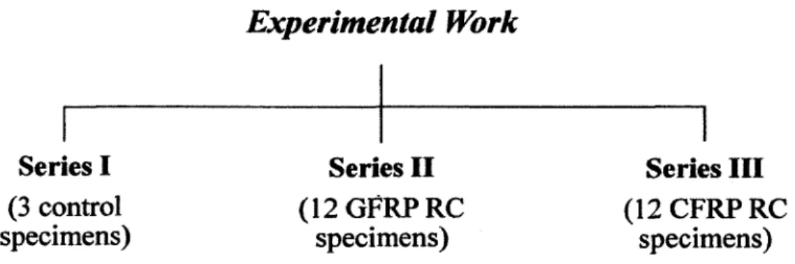
To achieve the aforementioned objectives o f this research, extensive experimental and analytical programs were conducted. The experimental phase includes the construction and testing o f twenty seven full scale circular reinforced concrete columns, 300 mm in diameter and 1500 mm in height, reinforced with FRP bars and stirrups and divided into three series as follows:
• Series I: includes 3 reference columns; one plain column and two columns reinforced with steel bars and stirrups.
• Series II: includes 12 columns internally reinforced with GFRP bars and spiral/hoops stirrups.
• Series III: includes 12 columns reinforced longitudinally with CFRP bars and confined transversely with CFRP stirrups.
In this study, the test parameters were proposed to include the following variables: type o f reinforcement, longitudinal reinforcement ratio, the volumetric ratios, diameters, and spacing o f spiral reinforcement, confinement configuration (spirals versus hoops), and lap length o f hoops.
The theoretical phase included developing an analytical model to accurately simulate a complete stress-strain curve for short FRP-circular reinforced concrete columns. The efficiency and accuracy o f the model will be verified against the experimental results. Afterwards, the model will be used to conduct a parametric study.
1.5
Structure of the Dissertation
This dissertation consists o f seven chapters, references, list o f figures, and symbols. The content o f these chapters is as follows:
Chapter 1: This chapter defines the problem and presents the main objectives o f this
study, followed by the mythology to achieve the objectives and scope o f this research study. And the structure o f the dissertation is presented.
Chapter 2: This chapter provides a literature review concerning the behavior o f RC
compression member. A full historical review which deals with the previous work on FRP mechanical properties, the main factors influencing the axial behavior o f RC members under axial load, and the currently available equations for predicting axial
capacity of reinforced columns compression members in the design codes and guidelines in North America.
Chapter 3: This chapter describes the experimental work program, specimens’ details,
the used materials, specimens’ fabrications, test procedure, test setup, and measuring devices.
Chapter 4: This chapter presents the first paper in this dissertation which accepted in
ASCE’s Journal o f Composites for Construction. The paper is titled “Axial Capacity o f Circular Concrete Columns Reinforced with GFRP Bars and Spirals”. This paper shows the experimental test results investigation on the axial behavior o f nine full scale circular reinforced concrete columns reinforced with GFRP bars and spiral stirrups, in addition to, three reference columns. The analysis and discussions o f these results are presented. These discussions are based on modes o f failure, effect o f various test variables on the behavior o f GFRP RC columns, and load-strain response o f tested specimens. Research findings indicate the increase o f transverse volumetric ratio enhance the ductility and concrete core strength o f GFRP RC columns.
Chapter 5: This chapter presents the second paper in this dissertation which accepted in
ASCE’s Journal o f Composites for Construction. The paper is titled “Strength and Axial Behavior o f Circular Concrete Columns Reinforced with CFRP Bars and Spirals”. The paper aims to investigate the behavior performance o f circular columns RC columns reinforced with CFRP bars and spiral stirrups. The results were presented in terms o f strength, ductility, axial stress-strain relationship, volumetric strain, and load-strain responses. Comparisons between the experimental test results and the theoretical predictions by three North American codes and design guidelines are performed. Based on the test results and the analysis the design equation equations are modified to accurately predict the nominal axial capacity o f circular RC columns internally reinforced with CFRP bars and spiral stirrups.
Chapter 6: This chapter presents the theoretical investigation o f this dissertation. The
purpose o f this study is to present a constructive critical review o f the state-of-the-art o f design methodologies available for the case o f short confined concrete columns using FRP bars and stirrups to predict maximum concrete core stress and corresponding concrete strain. Also, the theoretical approach developed a new incremental stress-strain relationship o f confined concrete to simulate the behavior o f RC circular column reinforced with GFRP/CFRP bars and hoop/spiral stirrups under concentric compression load. The results o f the analysis are compared with experimental values. Based on the experimental data obtained in this study, new proposed equations and a modified expression for the confined concrete core strength and stress-strain relationship are introduced. Finally most of the content o f this chapter are included in two papers.
Chapter 7: This chapter includes a summary o f this investigation and the overall
conclusions based on the experimental and theoretical results conducted in this dissertation. As well as, recommendations for further research work are also given.
CHAPTER 2
LITERATURE REVIEW
2.1
Introduction
Columns are compression members which transmit loads from the higher levels to the lower levels, and then to the soil trough the foundations. Since columns are the most important elements o f the structure, failure of one column in a critical location can cause a progressive collapse of adjoining floors and may reach to collapse o f the entire structure. In this respect, increasing column durability and avoidance o f steel corrosion o f columns reinforcement is very important subjects to reduce the structure failure.
Previous researches conducted on columns by were concerned mainly with increasing columns capacities by studying effect o f longitudinal reinforcement ratio, transverse reinforcement ratio, concrete compressive strength and using external FRP warps. In this study, it is intended to study and investigate the behavior o f circular concrete columns reinforced with GFRP or CFRP longitudinal bars and spiral or hoops stirrups with respect to specific design and detailing experimental parameters.
2.2
Plain Concrete Behavior
The axial behavior o f plain concrete has been widely studied by researchers for the past century, and is widely dependent on the specifications o f the concrete. The water-cement ratio, cement and aggregate characteristics, concrete unit weight, type o f curing and age, all play a significant role in the behavior (Carreira and Chu 1985). The plain concrete behavior is best understood from the axial compression o f concrete cylinders taken from the concrete mix. Concrete gains most o f its ultimate strength in the first 28 days after construction, during which time the type o f curing system will affect the overall strength. The testing o f the cylinders at 28 days will result in a stress-strain plot that will rise until
ultimate strength and then descend quickly when the concrete crushes. Figure 2-1 shows the typical stress-strain response o f plain concrete cylinders.
- CO U fM w + lf h i eo n cr ct* 3 ■ W n. mofctod Cylinders •.0 •.0 40 7.S 0.0030 9.S 4.0 0.0032 3.4 ksi 2.0 0 .0 0 2 0 • D ali Strain
Figure 2-1: Plain concrete stress-strain diagrams (Carreira and Chu 1985)
2.3
Fibre Reinforced Polymer Composite Material
“FRP” is an acronym for fiber reinforced polymers, which some also call fiber reinforced plastics. The term composite material is a generic term used to describe a judicious combination o f two or more materials to yield a product that is more efficient from its constituents. One constituent is called the reinforcing or fiber phase (one that provides strength); the other in which the fibres are embedded is called the matrix phase. The matrix, such as a cured resin-like epoxy, polyester, vinyl ester, or other matrix acts as a binder and holds the fibres in the intended position, giving the composite material its structural integrity by providing shear transfer capability. Figure 2-2 shows the concept o f FRP composite.
FIBRES POLYMER FRP
MATRIX
Figure 2-2: Basic material components o f FRP composite
Three FRPs are commonly used (among others): composites containing glass fibres are called glass fiber reinforced polymers (GFRP); those containing carbon fibres are called carbon fiber reinforced polymers (CFRP); and those reinforced with aramid fibres are referred to as aramid fiber reinforced polymers (AFRP).
Glass fibers are the most common o f all reinforcing fibers for polymeric matrix composites. The principal advantages o f glass fibers are low cost, high tensile strength, high chemical resistance, and excellent insulating properties. The disadvantages are relatively low tensile modulus and high density (among the commercial fibers), and relatively low fatigue resistance. On the other hand, carbon fibers are available with a variety o f tensile modulus. In general, the low-modulus fibers have lower density, lower cost, higher tensile and compressive strengths, and higher tensile strains-to-failure than the high-modulus fibers. Among the advantages o f carbon fibers are their exceptionally high tensile strength, very low coefficient o f linear thermal expansion, low inter-laminar shear strength, high fatigue strengths, and high thermal conductivity. (Mallick 2007)
Use o f composite materials was pioneered by the aerospace industry beginning in the 1940’s, primarily because o f the material’s high-performance and lightweight qualities. Today their potential is being harnessed for many uses. Advanced composite materials, so called because o f their many desirable properties, such as high performance, high strength-to-weight and high stiffness-to-weight ratios, high energy absorption, and outstanding corrosion and fatigue damage resistance are now increasingly used for civil engineering infrastructure such as buildings and bridges.
2.3.1 M echanical P rop erties o f F R P R ein forcin g B ars
FRP composites are used in a wide variety o f applications. A key element in evaluation o f FRP properties is the characterization o f the relative volume and/or mass content o f the various constituent materials. FRP reinforcing bars in concrete structures is strongly influenced by their physical and mechanical properties. Their mechanical properties provide unique benefits to the product they are fabricated into. This section presents testing methods and mechanical properties o f bars such as:
• Axial tensile strength. • Compressive strength. • Shear strength.
• Bond strength.
• Bend portion strength.
2.3.1.1 Axial Tensile Strength
Axial tension testing o f high strength unidirectional composites is often a challenge because load should be transmitted from the testing apparatus to the specimen via shear, and the shear strength o f a unidirectional composite is typically much lower than its axial tensile strength. Further, shear gripping will load the external fibers more than the internal ones causing shear lag and progressive fiber failure. To avoid these problems, end tabs are required when testing flat laminates. Special anchors are required for testing
FRP rods and bars by inserting their ends into steel cylinders that are subsequently filled with either a polymer resin or a cement-based grout as described in ACI 440.1R-06 (2006), as shown in Figure 2-3. Also, CSA S807-10 (2010) specified ASTM D7205/D7205M-06 (2006) standard method to get the bar tensile properties. Table 2-1 to Table 2-5 represent axial tensile strength and modulus o f elasticity for FRP bars as provided in the North American codes and design guidelines and as produced by different companies.
Threaded plug for attachment to load head (not used if anchor is placed in grips) PVC cap with central hole
fitting FRP bar Steel tube
m
Anchor filling material FRP b ar---Threaded, welded, or clamped plug with central hole fitting FRP bar
outer tube diameter
A - A
■ Band clamp
Figure 2-3: Anchor length according to ASTM D 7205/D 7205M -06 (2006) Table 2-1: Typical mechanical properties o f FRP bars (CSA S807-10)
Trade Name
Minimum Specified Tensile Strength
[MPa]
M odulus o f Elasticity E (GPa)
Grade I Grade II Grade III
Carbon Glass 1100-1300 600-750 80.0 40.0 110.0 50.0 140.0 60.0 * Grade I have the lowest value of E and Grade III have the highest value of E.
Table 2-2: Typical mechanical properties o f FRP bars (ACI 440.1R-06)
Fiber Type Tensile Strength (MPa) Modulus o f Elasticity (GPa) Aramid (Kelvar 49) Carbon (Toray T300) Glass (E-Glass) 1720-2540 600-3690 483-1600 41-125 120-580 35-51
Table 2-3: Typical mechanical properties o f ASLAN FRP bars manufactured by Hughes Brothers Inc.
Trade Name Tensile M odulus o f Ultimate Tensile
Strength [MPa] Elasticity (GPa) Strain
CFRP Aslan 200 2068-2241 GFRP Aslan 100 620-827 124 46 0.0167-0.0181 0.0134-0.0179 * As provided by the manufacturer.
Table 2-4: Typical mechanical properties o f ComBAR GFRP bars manufactured by Schock Inc. Tensile Trade Name Strength [MPa] Modulus o f Elasticity (GPa) Ultimate Tensile Strain GFRP > 1000 >60 0.0261
* As provided by the manufacturer.
Table 2-5: Typical mechanical properties o f V-ROD GFRP bars manufactured Pultrall Inc.
Trade Name Tensile M odulus o f Ultimate
Strength (MPa) Elasticity (GPa) Tensile Strain
V- Rod LM 588 - 804 4 0 -4 7 0.0134-0.0189
§2 V- Rod SM 703-938 5 0 -5 9 0.0133-0.0179
O
V- Rod HM 1000- 1372 6 0 -6 9 0.0151-0.0211 CFRP Carbon V-Rod 1356-1765 120-144 0.0120-0.0144 * LM means low strength; SM means standard strength; and HM means high tensile strength. * As provided by the manufacturer.
2.3.1.2 Compressive Strength
There is no standard axial compression test for FRP composites because there are many different failure modes (ACI 440.1R-06). The mode o f failure is buckling, ranging from buckling o f the entire specimen cross section or local micro buckling o f individual fibers. Thus, the greater resistance to buckling the test fixture provides, the higher the
compressive strength values obtained. For flat laminate FRP composites, many axial compression test methods in current use are some variation o f the Celanese compression test as in ASTM D3410 (2008). This test uses a thin, straight-sided specimen that looks very much like an axial tension specimen except that the distance between tabs is much smaller. Testing o f FRP bars in compression is typically complicated by the occurrence o f fibre micro-buckling due to the anisotropic and non-homogeneous nature o f the FRP material, and can lead to inaccurate measurements. Therefore, standard test methods are not established yet. For the case o f FRP bars, reductions in the compressive strength by 50% must be considered (Deitz et al. 2003).
2.3.1.3 Shear Strength
Most FRP bar composites are relatively weak in inter-laminar shear where layers o f unreinforced resin lie between layers o f fibers. Because there is usually no reinforcement across layers, the inter-laminar shear strength is governed by the relatively weak polymer matrix. On the other hand, interface problem between vinylester resin and carbon fiber appeared and results very low inter-laminar shear strength compared to glass fiber (Xiao 2004). In addition to, carbon fibers are more brittle than glass fiber with ultimate elongation 1.32% and 1.56% for carbon and glass fibers, respectively. Also, orientation o f the fibers in an off-axis direction across the layers o f fiber will increase the shear resistance, depending upon the degree o f offset. For FRP bars this can be accomplished by braiding or winding fibers transverse to the main fibers. Off-axis fibers can also be placed in the pultrusion process by introducing a continuous strand mat in the roving/mat creel.
2.3.1.4 Bond Strength (Pull-out Test)
The bond properties o f FRP bars have been extensively investigated by numerous researchers through different types o f tests, such as pull-out tests, splice tests, and cantilever beams, to determine an empirical equation for embedment length (Faza and GangaRao 1990; Benmokrane 1997). The bond stress o f a particular FRP bar should be based on test data provided by the manufacturer using standard test procedures that are
still under development at this time. ACI 440.1R-06 and CAS S807-10 specified a standard test method for bond strength o f FRP bars (B.3) as shown in Figure 2-4.
Loading Plata Applied^ Load ____ LZ Concrete B lo ck . Bond Breaker
m m ? *
- m m m y.' Elevation View FR P BarFigure 2-4: Schematic drawing o f pull-out test (B.3)
Bond failure between steel or FRP reinforcing bars and concrete occurs predominantly in two modes: pull-out and splitting. If the concrete around the bars is well confined, or the concrete cover is large, or the bar embedment length is small, bond failure occurs in pull- out mode. On the other hand, if the concrete cover is relatively small, and/or the concrete is unconfined, bond failure occurs in splitting mode. For most practical applications o f steel reinforced concrete, bond failure occurs by splitting.
For pull-out mode o f bond failure, the bond strength o f steel bars with short embedment lengths (less than 7 d b) called local bond strength is mainly dependent on the concrete compressive strength f c As the development or embedment length o f the bar increases, the bar force at bond failure increases but because the bond stress distribution along the embedment length becomes non-uniform, the average pullout bond strength at bond failure decreases.
2.3.1.5 Bend Portion Strength
FRP bent bars are being needed in many applications such as concrete bridge barriers (CSA S6-06-edition 2010; El-Salakawy et al 2003). In this case, the bond and the bar embedment length are become more critical. The problem is attributed to the significant reduction o f the tensile strength at the bend portions o f the FRP bars.