Publisher’s version / Version de l'éditeur:
Vous avez des questions? Nous pouvons vous aider. Pour communiquer directement avec un auteur, consultez la
première page de la revue dans laquelle son article a été publié afin de trouver ses coordonnées. Si vous n’arrivez pas à les repérer, communiquez avec nous à [email protected].
Questions? Contact the NRC Publications Archive team at
[email protected]. If you wish to email the authors directly, please see the first page of the publication for their contact information.
https://publications-cnrc.canada.ca/fra/droits
L’accès à ce site Web et l’utilisation de son contenu sont assujettis aux conditions présentées dans le site LISEZ CES CONDITIONS ATTENTIVEMENT AVANT D’UTILISER CE SITE WEB.
Paper (National Research Council of Canada. Institute for Research in
Construction); no. IRC-P-1374, 1986
READ THESE TERMS AND CONDITIONS CAREFULLY BEFORE USING THIS WEBSITE.
https://nrc-publications.canada.ca/eng/copyright
NRC Publications Archive Record / Notice des Archives des publications du CNRC :
https://nrc-publications.canada.ca/eng/view/object/?id=1f6deba7-cc8c-43c4-824c-dc86552f3eb2
https://publications-cnrc.canada.ca/fra/voir/objet/?id=1f6deba7-cc8c-43c4-824c-dc86552f3eb2
NRC Publications Archive
Archives des publications du CNRC
This publication could be one of several versions: author’s original, accepted manuscript or the publisher’s version. / La version de cette publication peut être l’une des suivantes : la version prépublication de l’auteur, la version acceptée du manuscrit ou la version de l’éditeur.
For the publisher’s version, please access the DOI link below./ Pour consulter la version de l’éditeur, utilisez le lien DOI ci-dessous.
https://doi.org/10.4224/40001801
Access and use of this website and the material on it are subject to the Terms and Conditions set forth at
Influence of restraint on fire performance of reinforced concrete
columns
R e f
Ser
I
I
- / k / J y y
National Research
Conseil national
I*
Council Canada
de recherches Canada
N21d
Ino.
1374
'
BLDG
lnst~tute
for
lnstitut de
Research in
recherche en
Construct~on
construction
i
IRC PUB
I
Influence of Restraint on Fire
I
Performance of Reinforced
Concrete Columns
by T.T. Lie and T.D. Lin
Reprinted from
Fire Safety Science
-
Proceedings of
First International Symposium
Gaithersburg,
MD, 9-11 October 1985
p.
291 -300
(IRC Paper No. 1374)
Price $2.00
NRCC 25921
Influence of Restraint on Fire Performance
I
of Reinforced Concrete Column.
1
I
T. T. LIE
Division
of
Building ResearchNational Research Council of Canada
Ottawa, Ontario, KIA OR6, Canada
T. D. LIN
Portland Cement Association
Skokie, iliinois. USA
ABSTRACT
Experimental and theoretical studies were carried out an the effect of restraint on the fire resistance of reinforced concrete columns. Two tests were carried out an axially loaded columns fully restrained against thermal expansion. Bath experimental and theoretical studies indicate that full restraint of axial thermal expansion has little influence on the fire
performance of the columns. The maximum stresses in e fully restrained column
at the time that the restraining load is maximum, are considerably lower than those at the time of failure of the column.
INTRODUCTION
In a fire the expansion of ~tructural members due to heating ie often
restrained by the integrated surrounding structure. In the case of columns,
restraint occurs if the expansion of the column is resisted by the floors
above. As a consequence, additional load is imposed on the column; the
greater the number of floors above the column, the greater the increase in load. The increase in load may have an adverse effect an the fire resistance of the column.
meoretical studies 111 indicated that restraint against thermal expansion of a reinforced concrete column would not significantly affect its fire resistance. Facilities are now available for the testing of columns under restraint and for verification of theoretical results. Such tests have
been conducted recently at the National Research Council of Canede ae part of
a study undertaken in cooperation with the Construction Technology
Laboratories of the Portland Cement Association. The results of these tests, and the calculated results, are discussed in the present paper.
MAGNITUDE OF RESTRAINT
In a previous study
I l l ,
the magnitude of restraint was assessed byestimating the vertical stiffness of a floor slab as a function of its dimensions, and by assuming that the total vertical stiffness of the
vcsLralnlag structure 1s propoCLlur~a1 Lo the number oi floors above the
column. Depending on the number of floors and their individual vertical stiffness, the magnitude of the restraining forces can vary from close to zero Lo values close to those present when column expansion is fully restrained.
I n t h i s study two t e s t s were c a r r i e d out i n which t h e a x i a l expansion of
t h e columns was f u l l y r e s t r a i n e d . A f u l l r e s t r a i n t c o n d i t i o n was o b t a i n e d by
*
i n i t i a l l y applying t h e maximm allowable l o a d on t h e wlumns and p r e v e n t i n gt h e i r expansion d u r i n g t h e f i r e t e s t s by c o n t r o l l i n g t h e load. The l e n g t h s of t h e columns were kept c o n s t a n t u n t i l t h e load, which i n c r e a s e s i n i t i a l l y b u t 3 reduces l a t e r w i t h r e d u c t i o n of column s t r e n g t h , had r e t u r n e d t o i t s o r i g i n a l value. Then t h e l o a d was k e p t c o n s t a n t u n t i l t h e column f a i l e d . The maximum a l l o w a b l e load was determined according t o ACI 318-83 [21, u s i n g a
live-to-dead load r a t i o of 0.4 and t h e a c t u a l c y l i n d e r s t r e n g t h of t h e c o n c r e t e on t h e t e s t date.
TEST SPECIMENS1
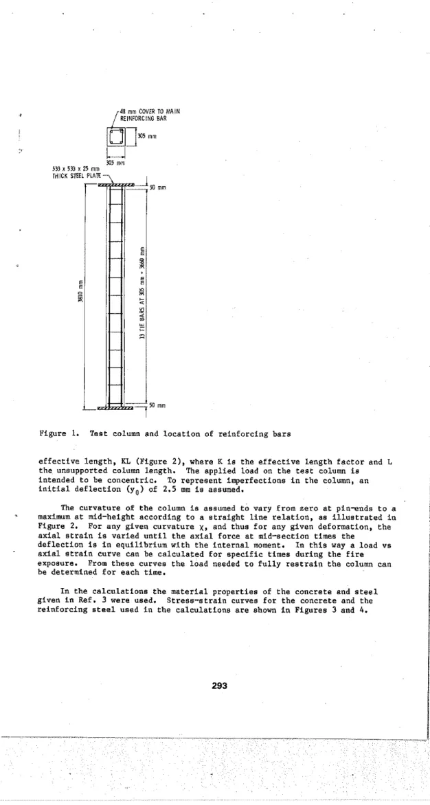
The specimens were square, t i e d , r e i n f o r c e d c o n c r e t e columns, made w i t h s i l i c e o u s aggregate. A l l were 3810 mm l o n g and had a c r o s s - s e c t i o n s i z e o f 305 x 305 mm. Twenty-five-mm diameter l o n g i t u d i n a l r e i n f o r c i n g b a r s and 10-mm diameter t i e s were used. The l o c a t i o n of t h e bars, which were welded t o s t e e l end p l a t e s , and t h e l o c a t i o n s of t h e t i e s a r e shown i n Figure 1.
The y i e l d s t r e s s of t h e main r e i n f o r c i n g b a r s was 444 MPa and t h a t of t h e t i e s was 427 m a . The u l t i m a t e s t r e n g t h was 730 ME'a f o r t h e main b a r s and 671 MPa f o r t h e t i e s .
The designed c o n c r e t e mix had a s t r e n g t h of about 35 MPa. Its
composition p e r c u b i c metre was a s f o l l o w s : cement
,
325 kg; w a t e r , 140 kg; sand, 874 kg; c o a r s e a g g r e g a t e , 1058 kg.The average compressive c y l i n d e r s t r e n g t h of t h e c o n c r e t e of t h e two columns t e s t e d , measured on t h e t e s t d a t e s , was 42.6 MPa f o r column A and 36.7 MPa f o r column B. The moieture c o n d i t i o n a t t h e c e n t e r of e a c h column was approximately e q u i v a l e n t t o t h a t i n e q u i l i b r i u m w i t h a i r of 75% r e l a t i v e humidity a t room temperature.
Chromel-alumel thermocouples, 0.91 mm t h i c k , were i n s t a l l e d a t mid-height of t h e columns f o r measuring c o n c r e t e temperatures a t d i f f e r e n t l o c a t i o n s i n t h e cross-section.
CALCULATION PROCEDURE
The c a l c u l a t i o n of t h e f i r e performance of t h e columns i n v o l v e s t h e c a l c u l a t i o n of t e m p e r a t u r e s i n t h e column, i t s deformations, and t h e s t r e s s e s i n i t . The c a l c u l a t i o n procedure i s d e s c r i b e d i n d e t a i l i n r e f e r e n c e 3. only a b r i e f d e s c r i p t i o n of t h e method w i l l be given here.
The column t e m p e r a t u r e s a r e determined by a f i n i t e d i f f e r e n c e method. The coluan c r o s s s e c t i o n i s divided i n t o a l a r g e number of elements. F a r each element a h e a t and m o i s t u r e balance i s made. The e f f e c t of m o i s t u r e on temperature i s taken i n t o account by assuming t h a t i n each element t h e m o i s t u r e starts t o e v a p o r a t e when t h e element temperature r e a c h e s 10O0C.
The load a n t h e column d u r i n g exposure t o f i r e is c a l c u l a t e d by a method based on a l o a d - d e f l e c t i o n a n a l y s i s , which i n t u r n i a based on a s t r e s e - s t r a i n a n a l y s i s of cross s e c t i o n s . I n t h i s method, t h e t e s t columns, which a r e f i x e d a t t h e ends d u r i n g t h e t e s t s , a r e i d e a l i z e d as pin-ended columns of reduced
/48 mm COVLR TO M I N
REINIORCING BAR
Figure 1. T e s t column and l o c a t i o n of r e i n f o r c i n g b a r s
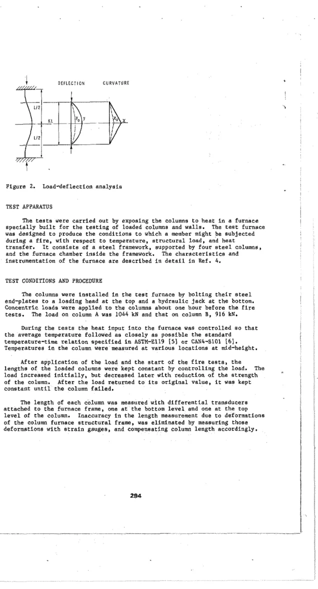
e f f e c t i v e l e n g t h , KL ( F i g u r e 2 ) , where K i s t h e e f f e c t i v e l e n g t h f a c t o r and L t h e u n s u v ~ o r t e d
.
.
column l e n g t h . " The a o n l i e d load on t h e t e s t column i s. .
intended t o be c o n c e n t r i c . To r e p r e s e n t i m p e r f e c t i o n s i n t h e column, a n i n i t i a l d e f l e c t i o n ( y o ) of 2.5 mm i s assumed.The c u r v a t u r e of t h e column i s assumed t o vary from z e r o a t pin-ends t o a maximum a t mid-height a c c o r d i n g t o a s t r a i g h t l i n e r e l a t i o n , a s i l l u s t r a t e d i n Figure 2. For any g i v e n c u r v a t u r e y,, and t h u s f o r any g i v e n deformation, t h e a x i a l s t r a i n is v a r i e d u n t i l t h e a x i a l f o r c e a t mid-section times t h e
d e f l e c t i o n i s i n e q u i l i b r i u m w i t h t h e i n t e r n a l moment. I n t h i s way a l o a d v s
a x i a l s t r a i n curve can be c a l c u l a t e d f o r s p e c i f i c times during t h e f i r e exposure. From t h e s e curves t h e l o a d needed t o f u l l y r e s t r a i n t h e column can be determined f o r each time.
I n t h e c a l c u l a t i o n s t h e m a t e r i a l p r o p e r t i e s of t h e c o n c r e t e and s t e e l g i v e n i n Ref. 3 were used, S t r e s s - s t r a i n curves f o r t h e c o n c r e t e and t h e r e i n f o r c i n g s t e e l used i n t h e c a l c u l a t i o n s a r e s h o r n i n F i g u r e s 3 and 4.
t
D E F L E C T I O N C U R V A T U R tFigure 2. Load-deflection analysis
TEST APPARATUS
The tests were carried out by exposing the columns to heat in a furnace specially built far the testing of loaded columns and walls. The test furnace was designed to produce the conditions to which a member might be subjected during a fire, with respect to temperature, structural load, and heat
transfer. It consists of a steel framework, supported by four steel columns, and the furnace chamber inside the framework. The characteristics and
instrumentation of the furnace are described in detail in Ref.
4.
TEST CONDITIONS AND PROCEDURE
The columns were installed in the test furnace by bolting their steel end-plates to a loading head at the top and a hydraulic jack at the bottom. Concentric loads were applied to the columns about one hour before the fire
tests. The load on column A was 1044 kN and that on column B, 916 kN.
During the tests the heat input into the furnace was controlled so that
the average temperature followed as closely as possible the standard
temperature-time relation specified in ASTM-El19 (51 or CAN4-S101 I 6 l .
Temperatures in the column were measured at various locations at mid-height. After application of the load and the start of the fire tests, the lengths of the loaded columns were kept conetant by controlling the load. The
load increased initially, but decreased later with reduction o t the strength I
of the column After the load returned to its original value, it was kept I
constant until the column failed.
I
The length of each column was measured with differential transducers
attached to the furnace frame, one at the bottom level and one at the top
level of the column. Inaccuracy in the length measurement due to deformations of the column furnace structural frame, was eliminated by measuring those deformations with strain gauges, and compensating column length accordingly.
S T R A I N . f
Figure 3. S t r e s s - s t r a i n curves f o r c o n c r e t e a t v a r i o u s temperatures (fko = 35 MPa)
S T R A I N , r s
1
Figure 4. S t r e s s - s t r a i n curves f o r t h e r e i n f o r c i n g s t e e l a t v a r i o u s t e m p e r a t u r e s (f = 443 MPa)
Y O
The columns were considered t o have f a i l e d and t h e t e s t s were terminated when t h e h y d r a u l i c j a c k , which had a maximm speed of 76 m l m i n , could no longer m a i n t a i n t h e a p p l i e d load.
RESULTS AND DISCUSSION
Column Temperatures
Previoua a t u d i e s I31 i n wh4rh npvr?nl eolumns were t e s t e d , a h w e d thaL t h e mathematical model used f o r t h e c a l c u l a t i o n of temperature i n s i l i c e o u s
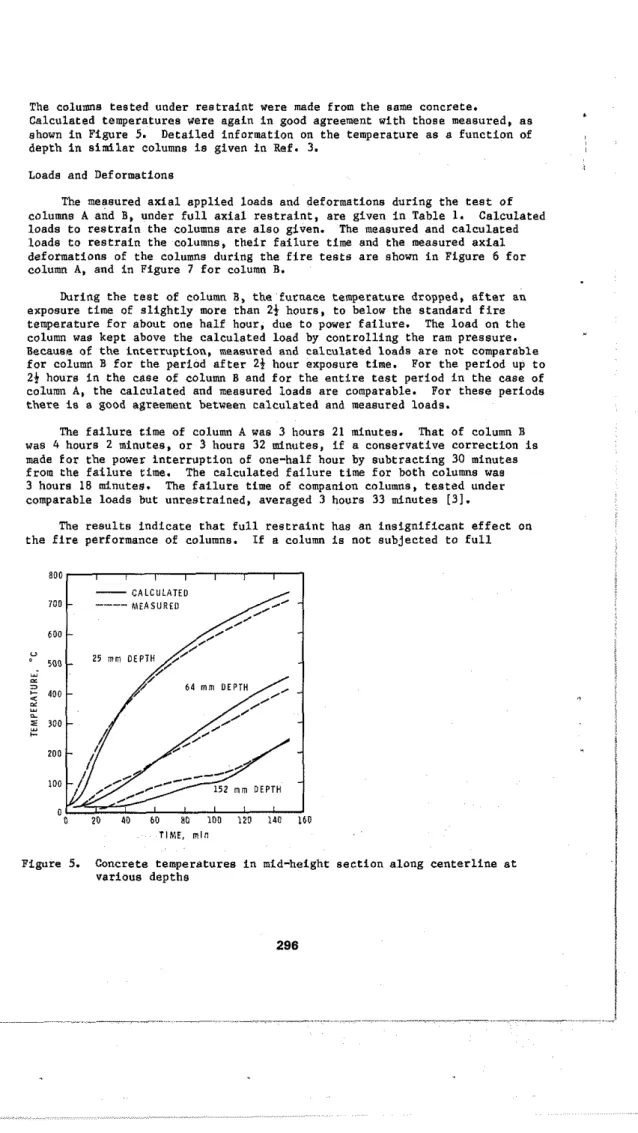
The columns tested under restraint were made from the same concrete.
Calculated temperatures were again in good agreement with those measured, as
ahown in Figure 5. Detailed information on the temperature as a function of
depth in similar columns is given in Ref. 3.
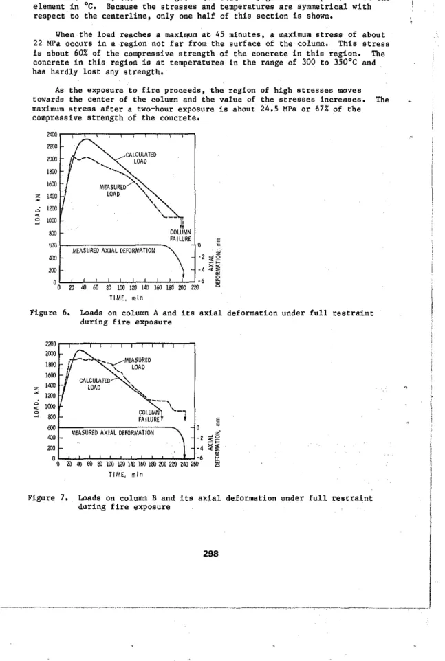
Loads and Deformations
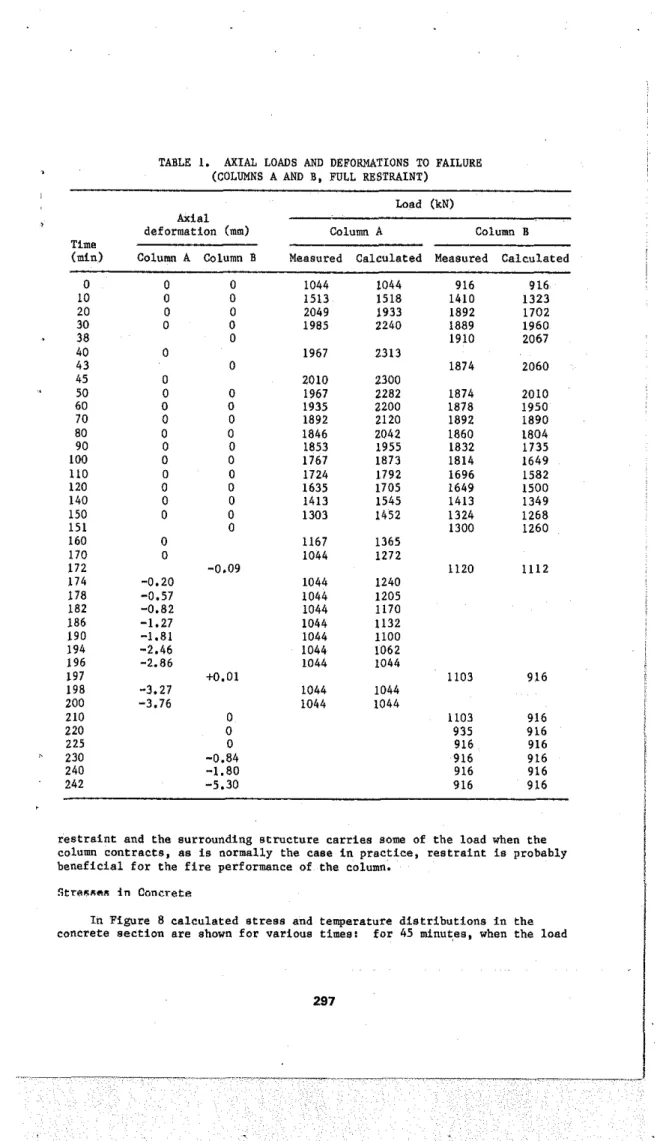
The measured axial applied loads and deformations during the test of
columns
A
and B, under full axial restraint, are given in Table 1. Calculatedloads to restrain the columns are also given. The measured and calculated loads to restrain the columns, their failure time and the meaeured axial
deformations of the columns during the fire tests are shown in Figure 6 for
column A, and in Figure 7 far column B.
Daring the test of column B, the furnace temperature dropped, after an
exposure time of slightly more than 2 t hours, to below the standard fire
temperature for about one half hour, due to power failure. The load an the
column was kept above the calculated load by controlling the ram pressure. Because of the interruption, measured and calculated loads are not comparable
for column B far the period after
21
hour exposure time. For the period up to2 1 hours in the case of column 8 and for the entire test period in the case of
column
A,
the calculated and measured loads are comparable. Far these periodsthere is s good agreement between calculated and measured loads.
The failure time of column
A
was 3 hours 21 minutes. That of column Bwas 4 hours 2 minutes, or 3 hours 32 minutes, if a conservative correction is
made for the power interruption of one-half hour by subtracting 30 minutes
from the failure time. The calculated failure time for both columns was
3 hours 18 minutes. The failure time of companion columns, tested under
comparable loads but unrestrained, averaged 3 hours 33 minutes [31.
The results indicate that full restraint has an insignificant effect on the fire performance of columns. If a column ia not subjected to full
TIME, m l n
Figure 5. Concrete temperatures in mid-height
various depths
TABLE
I.
AXIAL LOADS AND DEFORMATIONS TO FAILURE (COLUMNS A AND B, FULL RESTRAINT)Load (kN)
Axial
deformation (mm) Coluw A Column B
Time
-
(mid Column A Column B Measured Calculated Measured Calculated
restraint and the surrounding structure carries some of the load when the column contracts, as is normally the case in practice, restraint is probably beneficial for the fire performance of the column.
S t r r ~ r c a i n Concrete
1
In Figure 8 calculated stress and temperature distributions in the
on t h e r e s t r a i n e d column reaches a maximum, f o r 120 minutes, and f o r
198 minutes, when t h e column would f a i l . The upper f i g u r e s g i v e t h e s t r e s s i n
'
an element i n MPa; t h e lower f i g u r e s ( i n b r a c k e t s ) g i v e t h e temperature of t h e element i n 'C. Because t h e s t r e s s e s and temperatures a r e symmetrical w i t h I r e s p e c t t o t h e c e n t e r l i n e , only one h a l f of t h i s s e c t i o n i s shown.When t h e load reaches a maximum a t 45 minutes, a maximum s t r e s s of a b o u t 22 MPa occurs i n a region not f a r from t h e s u r f a c e of t h e column. T h i s s t r e s s
i s about 60% of t h e compressive s t r e n g t h of t h e c o n c r e t e i n t h i s r e g i o n . The c o n c r e t e i n t h i s region i s a t temperatures i n t h e range of 300 t o 350°C and has h a r d l y l a s t any s t r e n g t h .
As t h e exposure t o f i r e proceeds, t h e region of high s t r e s s e s moves
towards t h e c e n t e r of t h e column and t h e v a l u e of t h e s t r e s s e s i n c r e a s e s . The
.
maximum s t r e s s a f t e r a two-hour exposure i s about 24.5 MPa o r 67X of t h ecompressive s t r e n g t h of t h e concrete. COLUMN 0 . 2 100 - 4 .6 o n a 60 SO IW 1 n
im
160 iao no 220 T I M E . m l nF i g u r e 6. Loada on column A and i t s a x i a l deformation under f u l l r e s t r a i n t d u r i n g f i r e exposure
:
lmaFAILURE MEASURED AXIAL DiFORklAlION
no
o 20 M w e a i w i ~ i m ~ t o i s o m z n ~ d ~ z ~ T I M E , m l n
Figure 7. Loads on column B and i t s a x i a l deformation under f u l l r e s t r a i n t d u r i n g f i r e exposure
AT MAXIMUM LOAD; 45 mln AT INTERMEDIATE TIME: 120 mln 4 . t 9.7 L9.A 13.6 L6.0 17811 l 6 l Z l 16201 15981 11901 9.1 20.5 21.8 21.9 l l . 8 16721 I I b l I 1340) 1 2 P U 12811 12.1 21.6 21.2 19.3 i P . 1 1620) 1 1 6 0 11011 l i b 6 1 11211
11.e 21.a Is.> i6.8 15.5
I S P S I IZS61 (1461 (811 1691 i 1 . l 2111 I 8 . i 14.8 11.0 1590) 12811 11211 169) 1661 13.7 20.8 L1.i i I . 6 l 1 . i 11881 llill IL L 5 1 (631 I b I I i 3 . 6 20.5 11.6 12.8 10.6 I i S B I 12711 I L L 5 1 1691 ( i l l 1S.1 20.9 16.5 12.7 LO.& (5901 I Z B I I 1 1 2 l I ( 6 9 ) ( $ 6 1 13.0 20.1 17.1 13.6 11.9 9 9 I I I LL.9 2O.Z t8.7 L6.6 15.6 16201 0 4 0 1 (2011 11161 11291 9.3 19.3 20.0 19.7 1 9 . 1 16721 1 4 i l l I I l l D I 12961 19.81) 1.0 9.9 11.8 12.8 L3.2 11871 167%) 16201 11981 (1901
I
1
E
AT FAILURE TIME: 198 mln I i O l i I (2016) 19811 19661 (9121 19461, l I O L 6 1 19191 18bI) 11801 17551 17361 19871 I B I * ) 17331 1 6 i l I (6061 I I B O I 0 . 0 4 . 8 i l . + 20.5 25.2 21.1 19661 17901 16541 15581 I I O I I ( i l 7 l l 0.0 6.3 15.6 11.7 26.6 27.3 19521 17551 (6041 11071 1 1 1 9 1 ((161' 0.0 6.6 25.0 1L.I 23.2 23.1 l W 6 1 17381 15aOI 16751 l + i 6 > 13881 0.0 5.9 i l . 9 i 7 . 4 is.1 L8.l 19161 I I P B I 15801 111711 ( P I 6 1 (988) 0.0 4.5 9.B L2.b i 3 . I i2.6 19521 ( i i S 1 U O I I I I O I I 1'121 ($161' 0.0 2.8 6.6 8.2 8.h 8 . 2 1 19661 ( 7 9 I i l 16541 I I I B I lliill 14751. 0.0 1.0 9.7 $.9 5.3 19871 18441 (1111 1611) (601) ( 5 8 0 ) 0.0 0.0 0.9 1 . 9 2 . i (IOi6) 1I)LPI 18411 1 1 8 9 11151 I l l 8 1o.o a,e O.O @ , a ( i d a.0
i
l l O S + l 120!61 1 9 W I 19661 (9521 19461'
I
E
k 1 5 2 . 5 mm
---A
L 1 5 2 . 5 m m d 1 1 5 2 . 5 m m dFigure 8. Stresses (upper figure
-
MPa) and temperatures (lower figure-
O C )in concrete section of restrained column, calculated for various times
The maximum stress continues to increase with the duration of fire exposure. Although the inward movement of the region of high stresses has a delaying effect, the temperature in that region also continues to increase with the duration of exposure. At the time of failure the temperature of the concrete in that region, which lies near the core of the column, will have reached values of 500-60O0C; at this range the compressive strength of the concrete is reduced to about 70% of its initial strength. At the same time the stresses in that region will have reached the reduced compressive strength of the concrete.
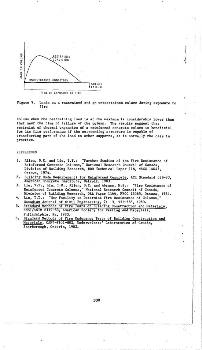
Failure occurs after the load on the restrained column has returned to its initial value, as illustrated in Figure 9. The theoretical failure time and stress distribution in the column at that time are equal to those for
an unrestrained column under the same load. In the tests only small
differences in failure time were found between the restrained and unrestrained columns. Thus the additional load to fully restrain the columns did not cause damage or significant permanent deformations in the columns.
CONCLUSIONS
Experimental and theoretical studies indicate that full restraint of axial thermal expansion of reinforced concrete columns has little influence on
UNRESTRAINED C O N D I T I O N
\
COLUMN FAILURE T I M E O F EXPOSURE TO FIRE
Figure 9. Load8 on a restrained and an unrestrained column during exposure to
fire
column when the restraining load is at the maximum is considerably lower than that near the time of failure of the column. The results suggest that restraint of thermal expansion of a reinforced concrete column is beneficial for its fire performance if the surrounding structure is capable of
transferring part of the load to other supports, as is normally the case in practice.
REFERENCES
1. Allen, D.E. and Lie, T.T.: "Further Studies of the Fire Resistance of
Reinforced Concrete Calumns," National &search Council of Canada, Division of Building Research, DBR Technical Paper 416, NRCC 14047, Ottawa. 1974.
2. Building Code Requirements far Reinforced Concrete ACI Standard 318-83,
8
3. Lie, T.T., Lin, T.D., Allen, D.E. and Abrams, M.S.: "Fire Resistance of
Reinforced Concrete Columns," National Research Council of Canada,
Division of Building Research, DBR Paper 1166, NRCC 23065, Ottawa, 1984.
4. Lie, T.T.: "New Facility to Determine Fire Resistance of Columns."
Canadian Journal of Civil Engineering,
1:
3, 551-558, 1980.5. S t a n d a r d l d i n ~ u i l d i n p : Construction and Materials,
ANSIIASTM E119-83, American Society for Testing and Materials,
Philadelphia, Pa, 1983.
6 . Standard Methods of Fire Endurance Tests of Building Construction and
Materials, CAN4-S101-M82, Underwriters' Laboratories of Canada, Scarborough, Ontario, 1982.