Publisher’s version / Version de l'éditeur:
Vous avez des questions? Nous pouvons vous aider. Pour communiquer directement avec un auteur, consultez la première page de la revue dans laquelle son article a été publié afin de trouver ses coordonnées. Si vous n’arrivez pas à les repérer, communiquez avec nous à PublicationsArchive-ArchivesPublications@nrc-cnrc.gc.ca.
Questions? Contact the NRC Publications Archive team at
PublicationsArchive-ArchivesPublications@nrc-cnrc.gc.ca. If you wish to email the authors directly, please see the first page of the publication for their contact information.
https://publications-cnrc.canada.ca/fra/droits
L’accès à ce site Web et l’utilisation de son contenu sont assujettis aux conditions présentées dans le site LISEZ CES CONDITIONS ATTENTIVEMENT AVANT D’UTILISER CE SITE WEB.
Internal Report (National Research Council of Canada. Institute for Research in Construction), 1996-03-01
READ THESE TERMS AND CONDITIONS CAREFULLY BEFORE USING THIS WEBSITE. https://nrc-publications.canada.ca/eng/copyright
NRC Publications Archive Record / Notice des Archives des publications du CNRC : https://nrc-publications.canada.ca/eng/view/object/?id=9771327d-a4e9-48c0-a8f9-bccf1d6aaec3 https://publications-cnrc.canada.ca/fra/voir/objet/?id=9771327d-a4e9-48c0-a8f9-bccf1d6aaec3
NRC Publications Archive
Archives des publications du CNRC
For the publisher’s version, please access the DOI link below./ Pour consulter la version de l’éditeur, utilisez le lien DOI ci-dessous.
https://doi.org/10.4224/20338384
Access and use of this website and the material on it are subject to the Terms and Conditions set forth at Experimental Studies on the Fire Resistance of Square Hollow Steel Columns Filled with Steel-Fibre-Reinforced Concrete
National Research Conseil national Council Canada de recherches Canada Institute for lnstitut de
Research in recherche en Construction construction
Experimental Studies on the Fire Resistance
of Square Hollow Steel Columns Filled with
Steel-Fibre-Reinforced Concrete
IRC Ser
Received on: 07-31-98 I n t e r n a l r e p o r t
by V.K.R. Kodur and T.T. tie
Internal Report No. 662
Date of Issue: March 1996
Th~s IS an Internal repon of the lnst~tute for Researcn In Construction Althougn not mended for genera olstrlbutlon, t may be clted as a reference In other publ~cat~ons
EXPERIMENTAL STLDlES ON THE FIRE RESISTANCE OF SQUARE HOLLOW STEEL COLUMNS FILLED WITH STEELFIBRE-REINFORCED
CONCRETE by
V.K.R. Kodur and T. T. Lie
ABSTRACT
Experimental studies were canied out to determine the fire resistance of square hollow steel columns filled with steel-fibre-reinforced concrete. The results of seven N1- scale fire resistance tests are described in this report. The variables included column dimensions, wall thickness of steel section, concrete strength, type of aggregate in the concrete, eccentricity of loading and load intensity. These studies were conducted as part of a research program aimed at developing simple design equations capable of predictkg the fire resistance of concrete-filled hollow steel columns.
EXPERIMENI'AL STUDIES ON THE FIRE RESISTLYCE OF SQUARE HOLLOW STEEL COLUMNS FTLLED WITH STEELFIBREREINFORCED
CONCRETE
by
V.K.R. Kodur and T. T. Lie
INTRODUCTION
Hollow steel sections are very efficient structural sections in resisting compression loads. By filling hollow structural section (HSS) columns with concrete, a substantial increase in the load-canying capacity can be achieved. In addition, a high fire resistance can be obtained without external fire protection for the steel. The elimination of such surface protection in turn increases space in the building and improves the architectural aesthetics. The fact that formwork is not required also provides a significant saving in construction cost and time.
These perceived benefits have stimulated research into the structural and fire
resistance performance of concrctc-filled hollow steel sections in several organizations around tbc world. For a number of years, tbc National Fire Laboratory of the Institute for Research in Construction, National ~esearch Council of Canada, has been engaged in studies aimed at developing methods for predicting the fire resistance of concrete-filled steel columns. Both experimental and numerical studies on the fire resistance of hollow steel columns filled with concrete were carried out with the support of the Canadian Steel Construction Council and the American Iron and Steel Institute.
Three types of concrete filling, namely plain, bar-reinforced and fibre-reinforced concrete, were considered in the study. Studies on circular and square hollow steel columns filled with plain concrete and bar-reinforced concrete were completed [I-61 and the work on HSS columns filled with steel-fibre-reinforced concrete is at an advanced stage [7,8].
This report discusses results for square hollow steel columns filled with fibre- reinforced concrete. The results of seven fire resistance tests on full-size square columns
are described in detail, including the column temperatures, axial deformations and fire resistances.
TEST SPECIMENS Dimensions
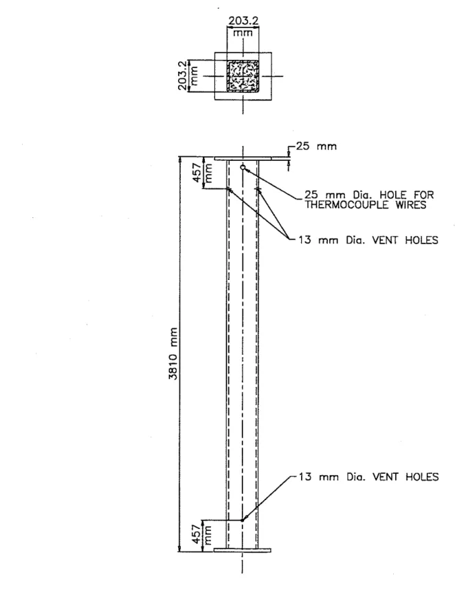
All seven columns were 3810 mm long from end plate to end plate and were of square cross section. The outside dimension, D, of the columns ranged from 152.4 mm to 304.8 mm. The wall thickness, t, was 6.35 mm for four sections, 12.7 rnm for two
sections and 9.35 mm for a single section. The dimensions of each column, together with designations, are listed in Table 1.
Materials
Steel hollow structural sections, meeting the requirements of CSA Standard G40.20-M81 [9], Class H, were used. The sections were made with Grade 350W steel
w h ~ h had a minimum yield strength of 350 MPa. The sections were supplied by Stelco Inc
.
The end plates were constructed using mild steel.Concrete
Two batches of concrete mix were supplied by Dufferin Concrete &om Ottawa. Columns SQ-4, SQ-6, SQ-8, and SQ-16 were cast from the first batch which contained siliceous aggregate while the other three columns SQ-3, SQ-15, and SQ-21 were cast from the second batch of concrete which contained carbonate aggregate. The mixes were made with general purpose Type 10 Portland cement, carbonate or siliceous stone and silica based sand. RIBTEC' steel fibres of the XOREX type, supplied by Ribbon
Technology Corporation [lo], were used as reinforcement. The fibres, which were 50 mm long, had an equivalent diameter of 0.9 mm, and an aspect ratio of 57. The percentage yf steel fibres in the concrete mix was 1.76 percent b;! mass. Superplasticizer, Mighty 150 ,
and retarding admixtures, Master Builder 100 XR
,
were added to the mix to improve workability. Batch quantities of the concrete are given in Table 2. The 28-day cylinder compressive strengths were 41.6 and 42.2 MPa respectively.Fabrication
Steel Column
The hollow steel sections were fabricated by cutting the supplied sections to 3760 mm in length. Steel end plates were then welded to both section extremities, with special attention being given to the centering and perpendicularity of the end plates. The total column length was 3810 mm including end plates.
The hoILow steel sections and end plates were first joined by a groove weld.
Secondly, a fillet weld was added around the outside perimeter of the hollow steel section. AWS 5.1 8 Type E705-6 welding rods were used for both welds. Figure 1 shows
elevation and cross-sectional details of a typical column.
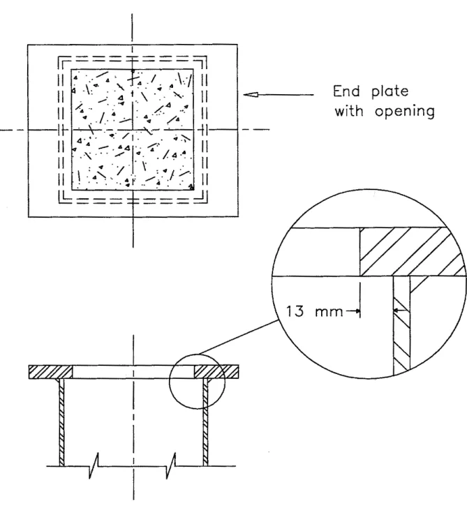
Before assembly, a hole was cut in each plate to provide an opening through which the concrete was poured. The hole was approximately 25 mm smaller than the inside width of the section. This construction provided a 13 mm lip around the inside perimeter to transfer the load from the steel plate to the concrete filling. The end plate connection detail is shown in Figure 2.
Five smaIl holes were drilled in the walls of the steel sections (see Figure 1). Two pairs, 13 mrn in diameter, located 457 rnm from each end of the columns, were provided as vent holes for the water vapour produced during the experiment. The fifth hole, 25 mm in diameter, located near the top end plate, was used for entry of thermocouple wires. Concrete Placement
The concrete was mixed in a truck mixer. The steel fibres were added to the fresh concrete and mixed for approximately 5 minutes to provide uniform dispersion. The columns were put in the upright position and filled with concrete. A concrete placement bucket and a funnel were used to deposit the concrete in the steel column. An internal 'Certain commercial products are identified in this paper in order to adequately specify the experimental details. In no case does such identification i m ~ l v recommendations or endorsement bv the National
Research Council of Canada, nor does it implG that the product or material idenlified
k
the best available for the purpose.vibrator was used to consolidate the concrete inside the column. The top surface of the column was finished with a small trowel. The section was sealed at both ends with
polyethylene sheet and tape to avoid moisture leaks. The columns were left upright for 28 days. then stored horizontally at room temperature, until the test date with no particular curing measures being taken. In general, one year or more elapsed between the time a column was poured and tbe time it was tested.
Before each test, the mqisture condition at the centre of a column section was measured by inserting a Vaisala moisture sensor into a hole drilled in the concrete through one of the vent holes. In general, a moisture content, corresponding to approximately 85 to 95% relative humidity, was measured.
Instnunentation
Type K chromel-alumel thermocouples, with a thickness of 0.91
mm,
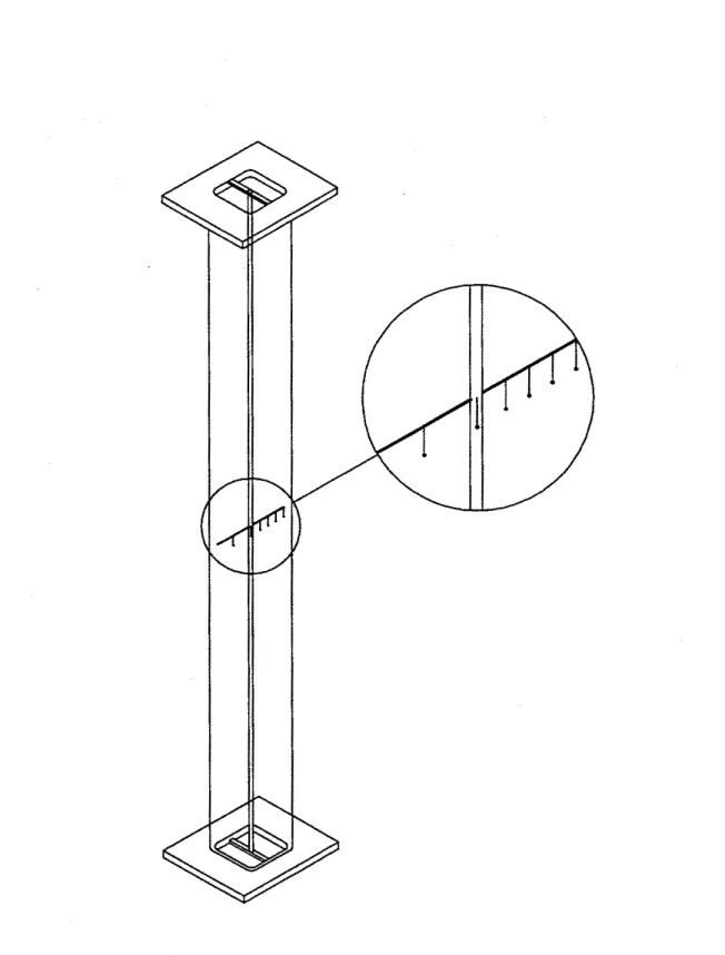
were usedfor measuring concrete temperatures at several locations across the mid-height section of the columns. The thermocouples were tied to a steel rod that was secured to a bar running along the longitudinal axis of the column. The bar was fixed at both ends of the column as shown in Figure 3. In addition, a thermocouple was attached to the steel wall of each column at mid-height. The thermocouple locations are shown in Figure 4.
TEST APPARATUS
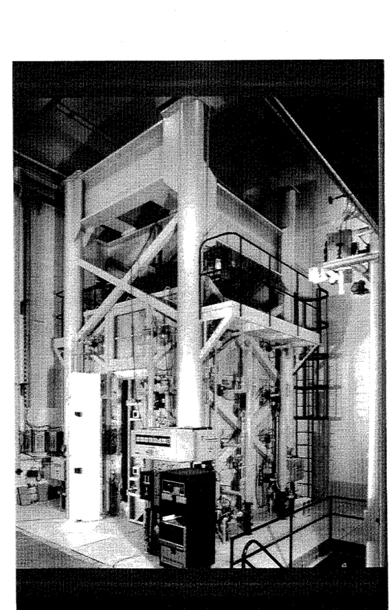
The tests were carried out by exposing the columns to heat in a furnace specially built for testing loaded columns and walls. The test furnace was designed to produce conditions to which a member might be exposed during a fire, i.e., temperatures, structural loads and heat transfer. It consisted of a steel framework supported by four steel columns, with the furnace chamber inside the framework (Figure 5). The characteristics and
instrumentation of the furnace are described in detail in Reference [l 11. Only a brief description of the furnace and the main components is given here.
Loading Device
A hydraulic jack with a capacity of 9778 kN produces a load along the axis of the test column. The jack is located at the bottom of the furnace chamber. Eccentric loads can be applied by means of hydraulic jacks, one at the top and one at the bottom of the column, located at a distance of 508 mm from the axis of the column. The capacity of the top jack is 587 kN and that of the bottom jack is 489 kN.
Furnace Chamber
The furnace chamber has a floor area of 2642 x 2642 mm and is 3048 mm high. The interior of the chamber is lined with insulating materials that efficiently transfer heat to the specimen. The ceiling and floor insulation protects the colwnn end plates from fire. It should be noted that only 3200 mm of the column is exposed to fire.
There are 32 propane gas burners in the furnace chamber, arranged in eight columns containing four burners each. The total capacity of the burners is 4700 kW. Each burner can be adjusted individually, which allows for a high degree of temperature uniformity in the furnace chamber. The pressure in the furnace chamber is also adjustable and was set somewhat lower than atmospheric pressure.
Instrumentation
The furnace temperatures were measured with the aid of eight chromel-alumel thermocouples. The thermocouple junctions were located 305 mm from the test specimcn, at various heights. Two thcrmocouples were placed opposite cach other at intervals of 61 0 mnl along the height of the furnacc chamber. The locations of their junctions and their numb6ring areshown in Figure 6. Thermocouples 4 and 6 were
located at a height of 610 mm fromthe floor, Thermocouples 2 and 8 at 1220 mm,
Thermocouples 3 and 5 at 1830 mm and Thermocouples 1 and 7 at 2440
mm
The temperatures measured by the thermocouples were averaged automatically and the average temperature used to control the furnace temperature.The loads were controlled by servocontrollers and measured with pressure
transducers. The accuracy of controlling and measuring loads is about 4 kN at lower load levels and relatively better at higher loads.
The axial deformation of the test columns was determined by measuring the displacement of the jack that supports the column. The rotation of the end plates of the columns was determined by measuring the displacement of the plates at a distance of 500 mm from the centre of the hinge at the top and bottom respectively. The
displacements were measured using transducers with an accuracy of 0.002 mm
TFST
CONDITIONSAND
PROCEDURES End ConditionsSix columns were tested with both ends fixed, i.e., restrained against rotation and horizontal translation. For this purpose, eight 19 mm diameter bolts, spaced regularly around the column, were used at each end to bolt the end plate to the loading head at the top and the hydraulic jack at the bottom. Column SQ-16 was tested under hinged end conditions, i.e., with restraint against horizontal translation only. The hinged condition was obtained by bolting the end plates to receiving plates with roller bearings at each end. Loading
All columns were tested under a concentric load, except Column SQ-16 where the load was eccentric by 25 mrn. The applied load on the columns ranged from 16 to 56% of the factored compressive resistance of the columns (C,) or 100 to 154% of the factored compressive resistance of the concrete core
(C3,
determined according to CSA Standard CSA/CAN-S16.1-M89 [12]. The factored compressive resistances of each column, as well as the applied loads, are given in Table 1. The factored compressive resistances of the columns were calculated using the effective length factors, K, recommended in CSNCAN-S 16.1-M89 for the given end conditions, i.e., 0.65 for fixed ends and 1 for pinned ends.All loads were applied approximately 45 minutes before the start of the test and were maintained until a condition was reached at which no further increase of the axial and rotational deformations could be measured. This condition was selected as the initial condition of the column deformations. The load was maintained constant throughout the test.
Fire Exposure
The ambient temperature at the start of each test was approximately 20°C. During the test, the column was exposed to heating controlled in such a way that the average temperature in the furnace followed, as closely as possible, the CANAJLC-SlO1 [13] or ASTM-El19 [14] standard temperature-time curve. This curve can be calculated using the following equation:
where: t = time in hours
T, = temperature of furnace in OC Recording of Results
The furnace. concrete and steel temperatures, as well as axial deformations of the columns, were recorded at two minutes intervals. In the case of the eccentricallv loaded column test, the lateral deflection of the column at mid-height and the rotation &the end plates of the column were measured with varying frequencies, depending on the rate of change of the measured quantities.
Failure Criterion
The columns were considered to have failed, and the tests were terminated, when the axial hydraulic jack, which has a
maximum
speed of 76 mm/min, could no longer maintain the load. The failure, which was determined by visual observation, ofColumns SQ-15 and SQ-21 was by compression while in the remaining columns the failure was by buckling. Significant bending was observed for Column SQ-16 which had an eccentric loading.
RESULTS
AND DISCUSSIONThe results of the seven column tests are summarized in Table 1, in which the column characteristics, test conditions, fire resistances and failure modes are given for each column. The furnace, concrete and steel temperatures recorded during ihe tests, as well as the axial deformations of the column specimens, are given in Tables A1 to A7 and plotted in Figures A1 to A7, in Appendix A. Positive axial deformation values indicate expansion of the column. Figures B1 to B6 in Appendix B show photographs of the column specimens after the fue tests.
Data from the tests indicate that high fire resistances can be obtained for square HSS columns filled with steel fibre-reinforced concrete. A comparison of the fire resistances in Table 1 with the fire resistances of similar HSS columns filled with plain concrete [1,3] indicates that the steel fibre-reinforced concrete filling increases the fire resistance.
The results for Column SQ-16 also indicate that a high fire resistance can be obtained under eccentric loads. The fire resistance of Column SQ-8 was only 60 minutes. This could be due to the high load intensity used for this particular column. Four of the five columns, subjected to axial loading, failed in buckling mode and this couId be attributed to higher slenderness ratio because of the lower cross-sectional dimensions.
The increased Fie resistance of fibre-reinforced concrete-filled columns,
as
properties of fibre-reinforced concrete. Results from the experimental studies carried out to determine mechanical properties at elevated temperatures [I51 indicate that the
compressive strength of fibre-reinforced concrete increases with temperature up to about 400°C. The steel fibres prevented early cracking and also contributed to the compressive strength of concrete at elevated temperatures.
These fire tests were carried out in order to validate mathematical models capable of predicting the fire resistance of HSS columns filled with steel fibre-reinforced concrete. The development of such methods is currently in progress [16]. The mathematical models will be used to conduct detailed parametric studies in order to determine the influence of various parameters on the fire resistance of HSS columns filled with steel fibre-reinforced concrete. In the interim, the test results given in this report can be used for assessing the fire resistance of square HSS columns filled with steel fibre-reinforced concrete that lie within the range of the variables examined in this study.
1. Lie, T.T. and Chabot, M., Experimental Studies on the Fire Resistance of Hollow Steel Columns Filled with Plain Concrete, IRC Internal Reuort No. 61 1, National Research Council of Canada, Institute for ~esearch in ~oktruction, Ottawa, Ontario,
1992.
2. Chabot, M. and Lie, T.T., Experimental Studies on the Fire Resistance of Hollow Steel Columns Filled with Bar-Reinforced Concrete, IRC Internal RepoIt No. 628, National Research Council of Canada, Institute for Research in Construction, Ottawa,
O n t a r i n 1992~ --
3. Lie, T.T. and Chabot, M., A Method to Predict the Fire Resistance of Circular Concrete Filled Hollow Steel Columns, Journal of Fire Protection Engineering, 2(4),
1990, pp. 11 1-126.
4. Lie, T.T., Fire Resistance of Circular Steel Columns Filled with Bar-Reinforced Concrete, ASCE Journal of Sbuctural Engineering, 120(5), May 1994, pp. 1489-
1 cna . J " , .
5. Lie. T.T. and Irwin. R.J., Fire Resistance of Rectanrmlar Steel Columns Filled with B&-~einforced concrete, ASCE Journal of structural Engineering, 121(5), May
1995, pp. 797-805.
6. Lie, T.T. and Kodur, V.K.R.. Fire Resistance of Steel Columns Filled with Bar- Reinforced Concrete, ASCE Journal of Structural Engineering, 122(1), January 1996 - <
-.
7. Kodur, V.KR and Lie, T.T., Fire Resistance of Hollow Steel Columns filled with
Steel-%re-reinforced Concrete, Proceedings, Second University-Indm Workshop on Fibre Reinforced Concrete and other Composite$ Toronto, Canada, 1995, pp. 289- 302.
8. Lie, T.T. and Kodur, V.KR, Fire Protection of Hollow Steel C o h m through Concrete filling, Proceedings, First Canadian Society of Ci Engineering Construction Speciality Conference, VoL 3, Ottawa, Canada, 1995, pp. 215-224.
9. General Requirement for Rolled or Welded Structural Quality Steels - G40.20-M81, Canadian Standard Association, Toronto, Canada, 198 1.
10. RIBTEC. Carbon Steel Fibres for Concrete Reinforcement, Ribbon Technology Corporation, Gahanna, OH, U.S.A.
1 1. Lie, T.T., New Facility to Determine Fire Resistance of Columns, Canadian Journal of Civil Engineering, 7(3), 1980, pp. 551-558.
12. Limit State Design of Steel Shuctures, CAN/CSA-S16.1-M89, Canadian Standards Association, Toronto, Canada, 1989.
13. Standard Methods of Fire Endurance Tests of Building Construction and Materials, CANlLiLC-S 101, Underwriters' Laboratories of Canada, Scarborough, Canada, 1989.
14. Standard Methods of Fire Tests on Building Construction and Materials, ASTM El 19-88, American Society for Testing and Materials, Philadelphia, PA, USA, 1990. 15. Lie, T.T. and Kodw, V.K.R., Mechan~cal Properties of Fibre-Reinforced Concrete at Elevated Temperatures, IRC Internal Report No. 687, National Research Council of Canada, Institute for Research in Construction, Ottawa, Ontario, 1995.
16. Kodw, V.KR and Lie, T.T., Pedormance of Concrete-filled Steel Columns Exposed to Fie, Journal of Fire Protection Engineering, 7(2), April 1996, pp. 1-9.
Table 1. Summary of test parameters and results
* Eccentrically loaded (eccentricity
= 25 mm; pinned ends) Factored ResistanceC'r = Factored compressive resistance of concrete core of the column according to CAN3-S16.1-M89 Crc = Factored compressive resistance of concrete-filled HSS column according to CAN3-S 16.1-M89 Failure Mode
B = Buckling C = Compression
I
1
I,
'+I
SECTION A-ATOP VIEW
CDLUMN
U
COLUMN FURNACE CHAMBERFRUNT
VIEW
/- CEILING INSULATIDN
APPENDIX A
Table A 1 Temperatures and Axial Deformation of Column No. SQ - 3 1 6 1 8 2 0 2 2 2 4 2 6 2 8 3 0 3 2 3 4 36 3 8 4 0 4 2 4 4 46 48 5 0 5 2 5 4 5 6 5 8 6 0 6 4 68 72 7 6 8 0 Note : 422 425 1 8 7 2 7 1 4 1 4 570 5 7 1 2 8 3 6 1 2 1 1 5 594 596 3 2 8 9 0 3 5 2 1 642 6 4 3 3 7 8 116 5 1 3 4 678 678 427 14 2 7 0 5 6 708 7 1 0 4 6 1 166 8 9 70 739 7 4 1 482 184 1 0 9 79 763 763 5 0 5 202 1 2 6 92 772 772 538 232 1 3 9 1 0 7 784 783 566 2 6 1 1 5 1 1 2 2 798 7 9 8 596 287 1 6 2 130 807 E08 6 2 5 310 1 7 1 1 3 7 824 E25 6 5 3 3 3 3 1 7 7 1 4 2 824 E25 6 7 5 354 184 1 4 8 826 E27 696 373 1 9 3 1 5 5 842 8 4 2 714 392 212 164 844 644 7 2 5 412 2 3 1 1 7 0 854 6 5 5 734 4 3 1 250 1 7 9 8 7 1 6 7 1 7 4 1 450 269 1 8 6 879 E.78 750 469 288 200 8 8 3 684 762 487 306 2 2 1 886 686 774 505 3 2 3 239 8 9 1 8 9 2 787 522 340 257 893 8 9 4 797 538 357 274 894 8 9 4 809 553 3 7 3 290 904 905 8 2 1 568 389 305 907 908 8 3 3 584 404 3 2 1 908 909 8 4 2 599 419 335 919 919 8 5 3 613 435 350 925 925 8 6 2 627 449 366 937 937 8 8 0 6 5 1 477 395 930 930 8 8 9 6 7 1 5 0 3 424 944 945 904 6 9 1 528 452 946 946 912 709 5 5 1 480 958 958 924 724 575 506
:he test was terminated at 1 hour and 20 minutes
Std. Furn. T-P Axial Def
.
(mm) 0 . 0 0 3 . 2 2 8 . 0 8 9 . 7 6 1 2 . 4 8 1 5 . 1 5 1 7 . 4 0 1 9 . 1 7 2 0 . 6 1 2 1 . 2 6 2 1 . 5 0 2 1 . 5 0 2 1 . 3 4 2 0 . 0 8 1 6 . 8 5 1 2 . 7 6 9 . 5 9 7 . 3 4 5 . 7 2 4 . 6 1 3 . 5 3 2 . 6 6 1 . 8 8 1 . 2 2 0 . 6 2 0 . 0 8 - 0 . 4 3 - 1 . 0 4 - 1 . 6 7 - 2 . 2 7 - 3 . 0 8 - 5 . 0 0 - 7 . 7 2 - 1 1 . 2 6 - 1 6 . 7 0 - 3 3 . 7 8 Avg. Furn. TempColumn Cross- section Temp. (-C) Measured at Thermocouple No.
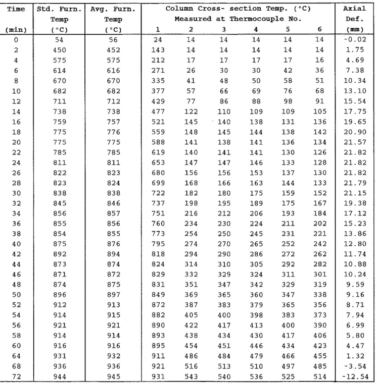
Table A2 Temperature and Axial Deformation of Column No. SQ - 4 Axial
1
Time (min) 0 2 4 6 8 1 0 1 2 1 4 1 6 1 8 2 0 2 2 2 4 2 6 2 8 3 0 3 2 3 4 3 6 3 8 4 0 4 2 4 4 4 6 4 8 5 0 5 2 5 4 5 6 5 8 6 0 6 4 6 8 7 2 Note: Def.1
Std. Furn. T a p ("C) 54 4 5 0 5 7 5 6 1 4 6 7 0 6 8 2 7 1 1 7 3 8 7 5 9 7 7 5 7 7 5 7 8 5 8 1 1 8 2 2 8 2 3 8 3 8 8 4 5 8 5 6 8 5 5 8 5 4 8 7 5 8 9 2 8 7 3 8 7 1 8 7 4 8 9 6 9 1 2 9 1 4 9 2 1 9 1 4 9 1 6 9 3 1 9 3 6 9 4 4 The test wasAvg. Furn. T a p ("C) 5 6 4 5 2 5 7 5 6 1 6 6 7 0 6 8 2 7 1 2 7 3 8 7 5 7 7 7 6 7 7 5 7 8 5 8 1 1 8 2 3 8 2 4 8 3 8 84 6 8 5 7 8 5 6 8 5 5 8 7 6 8 9 4 8 7 4 8 7 2 8 7 5 8 9 7 9 1 3 9 1 5 9 2 1 9 1 4 9 1 6 9 3 2 9 3 6 9 4 5 terminated
Column Cross- section Temp. ("C)
Measured at Thermocouple No.
1 2 3 4 5 6 2 4 1 4 1 4 1 4 1 4 1 4 1 4 3 1 4 1 4 1 4 1 4 1 4 2 1 2 1 7 1 7 1 7 1 7 1 6 2 7 1 2 6 3 0 3 0 4 2 3 6 3 3 5 4 1 4 8 5 0 5 8 5 1 3 7 7 5 7 6 6 6 9 7 6 6 8 4 2 9 7 7 8 6 8 8 9 8 9 1 4 7 7 1 2 2 1 1 0 1 0 9 1 0 9 1 0 5 5 2 1 1 4 5 1 4 0 1 3 8 1 3 1 1 3 6 5 5 9 1 4 8 1 4 5 1 4 4 1 3 8 1 4 2 5 8 8 1 4 1 1 3 8 1 4 1 1 3 6 1 3 4 6 1 9 1 4 0 1 4 1 1 4 1 1 3 0 1 2 6 6 5 3 1 4 7 1 4 7 1 4 6 1 3 3 1 2 8 6 8 0 1 5 6 1 5 6 1 5 3 1 3 7 1 3 0 6 9 9 1 6 8 1 6 6 1 6 3 1 4 4 1 3 3 7 2 2 1 8 2 1 8 0 1 7 5 1 5 9 1 5 2 7 3 7 1 9 8 1 9 5 1 8 9 1 7 5 1 6 7 7 5 1 2 1 6 2 1 2 2 0 6 1 9 3 1 8 4 7 6 0 2 3 4 2 3 0 2 2 4 2 1 1 2 0 2 7 7 3 2 5 4 2 5 0 2 4 5 2 3 1 2 2 1 7 9 5 2 7 4 2 7 0 2 6 5 2 5 2 2 4 2 8 1 8 2 9 4 2 9 0 2 8 6 2 7 2 2 6 2 8 2 4 3 1 4 3 1 0 3 0 5 2 9 2 2 8 2 8 2 9 3 3 2 3 2 9 3 2 4 3 1 1 3 0 1 8 3 1 3 5 1 3 4 7 3 4 2 3 2 9 3 1 9 8 4 9 3 6 9 3 6 5 3 6 0 3 4 7 3 3 8 8 7 2 3 8 7 3 8 3 3 7 9 3 6 5 3 5 6 8 8 2 4 0 5 4 0 0 3 9 8 3 8 3 3 7 3 8 9 0 4 2 2 4 1 7 4 1 3 4 0 0 3 9 0 8 9 3 4 3 8 4 3 4 4 3 0 4 1 7 4 0 6 8 9 5 4 5 4 4 5 1 4 4 6 4 3 4 4 2 3 9 1 1 4 8 6 4 8 4 4 7 9 4 6 6 4 5 5 9 2 1 5 1 6 5 1 3 5 1 0 4 9 7 4 8 5 9 3 1 5 4 3 5 4 0 5 3 6 5 2 5 5 1 4 at 1 hour and 1 3 minutes
Table A3 Temperature and Axial Deformation of Column No. SQ - 6 Column Cross- section Temp. ("C)
Measured at Thermocouple No.
1 2 3 4 5 6 2 8 - 2 7 3 1 9 1 9 - 2 7 3 - 2 7 3 1 2 0 - 2 7 3 1 9 1 9 - 2 7 3 - 2 7 3 1 9 7 - 2 7 3 2 2 2 1 - 2 7 3 - 2 7 3 2 7 3 - 2 7 3 3 1 2 7 - 2 7 3 - 2 7 3 3 3 4 - 2 7 3 4 4 4 0 - 2 7 3 - 2 7 3 3 8 7 - 2 7 3 5 8 5 4 - 2 7 3 - 2 7 3 4 3 2 - 2 7 3 7 3 7 0 - 2 7 3 - 2 7 3 4 7 2 - 2 7 3 9 1 8 8 - 2 7 3 - 2 7 3 5 0 8 - 2 7 3 1 1 4 1 1 0 - 2 7 3 - 2 7 3 5 4 0 - 2 7 3 1 3 5 1 3 4 - 2 7 3 - 2 7 3 5 7 0 - 2 7 3 1 3 4 1 3 1 - 2 7 3 - 2 7 3 5 9 5 - 2 7 3 1 3 7 1 2 9 - 2 7 3 - 2 7 3 6 2 4 - 2 7 3 1 4 4 1 3 4 - 2 7 3 6 5 0 6 5 0 - 2 7 3 1 5 3 1 3 9 - 2 7 3 2 6 1 6 7 5 - 2 7 3 1 6 4 1 4 8 - 2 7 3 - 8 0 6 9 2 - 2 7 3 1 7 7 1 6 0 - 2 7 3 - 2 7 3 7 1 7 - 2 7 3 1 9 3 1 7 3 - 2 7 3 - 2 7 3 7 3 5 - 2 7 3 2 1 1 1 8 7 - 2 7 3 - 2 7 3 7 4 1 - 2 7 3 2 3 1 2 0 4 - 2 7 3 - 2 7 3 7 5 6 - 2 7 3 2 5 2 2 2 4 - 2 7 3 - 2 7 3 7 7 3 - 2 7 3 2 7 3 2 4 5 - 2 7 3 - 2 7 3 7 8 3 - 2 7 3 2 9 5 2 6 8 - 2 7 3 - 2 7 3 7 9 5 - 2 7 3 3 1 7 2 9 0 - 2 7 3 - 2 7 3 7 9 9 - 2 7 3 3 3 8 3 1 1 - 2 7 3 - 2 7 3 8 0 7 - 2 7 3 3 5 8 3 3 2 - 2 7 3 - 2 7 3 8 1 5 - 2 7 3 3 7 7 3 5 1 - 2 7 3 - 2 7 3 8 2 4 - 2 7 3 3 9 6 3 7 0 - 2 7 3 - 2 7 3 8 4 1 - 2 7 3 4 1 5 3 8 9 - 2 7 3 - 2 7 3 8 5 2 - 2 7 3 4 3 3 4 0 6 - 2 7 3 - 2 7 3 8 6 2 - 2 7 3 4 5 1 4 2 3 - 2 7 3 - 2 7 3 8 7 4 - 2 7 3 4 6 9 4 4 1 - 2 7 3 - 2 7 3 8 8 2 - 2 7 3 4 8 6 4 5 8 - 2 7 3 - 2 7 3 8 8 7 - 2 7 3 5 0 2 4 7 5 - 2 7 3 - 2 7 3 8 9 3 - 2 7 3 5 1 8 4 9 1 - 2 7 3 - 2 7 3 9 0 2 - 2 7 3 5 3 3 5 0 6 - 2 7 3 - 2 7 3 9 0 8 - 2 7 3 5 4 7 5 2 1 - 2 7 3 - 2 7 3 9 1 2 - 2 7 3 5 5 9 5 3 5 - 2 7 3 - 2 7 3 9 1 3 - 2 7 3 5 6 8 5 4 7 - 2 7 3 - 2 7 3 9 1 3 - 2 7 3 5 8 1 5 5 7 - 2 7 3 - 2 7 3 9 2 0 - 2 7 3 5 9 7 5 6 3 - 2 7 3 - 2 7 3 9 2 3 - 2 7 3 6 1 4 5 6 9 - 2 7 3 - 2 7 3 9 2 7 - 2 7 3 6 3 0 586 - 2 7 3 - 2 7 3
at 1 hours and 2 2 minutes Time (min) 0 2 4 6 8 1 0 1 2 1 4 1 6 1 8 2 0 2 2 2 4 2 6 2 8 3 0 3 2 3 4 3 6 3 8 4 0 4 2 4 4 4 6 4 8 5 0 5 2 5 4 5 6 5 8 6 0 6 2 6 4 6 6 6 8 7 0 7 2 7 4 7 6 7 8 8 0 8 2 Note: Axial Def
.
(mm) 0 . 0 0 1 . 5 8 4 . 5 2 7 . 4 7 1 0 . 1 9 1 2 . 6 3 1 4 . 8 3 1 6 . 9 0 1 8 . 7 2 2 0 . 4 5 2 1 . 4 5 2 2 . 1 6 2 2 . 4 2 2 2 . 4 6 2 2 . 0 3 2 0 . 6 2 1 9 . 2 0 1 7 . 2 1 1 5 . 0 9 1 3 . 5 4 1 2 . 3 7 1 1 . 4 1 1 0 . 7 1 9 . 9 4 9 . 2 9 8 . 7 0 8 . 1 8 7 . 7 5 7 . 2 0 6 . 4 6 5 . 6 0 4 . 4 8 3 . 1 6 1 . 6 5 - 0 . 1 5 - 2 . 2 4 - 4 . 6 4 - 7 . 4 3 - 1 0 . 7 1 - 1 4 . 7 5 - 2 0 . 5 2 - 2 9 . 7 9 Std. Furn. T a p ("C) 5 0 4 1 6 5 9 0 6 6 7 6 9 2 7 1 1 7 2 7 7 4 9 7 7 0 7 7 6 7 9 5 7 8 8 8 1 9 8 2 3 8 2 4 8 1 1 8 6 6 8 7 3 8 5 5 8 9 9 9 0 9 8 9 6 9 0 2 8 6 6 8 9 4 8 9 7 8 9 8 9 1 9 9 2 8 9 1 6 9 2 7 9 2 9 9 4 6 9 5 0 9 5 7 9 6 3 9 6 4 9 6 6 9 5 7 9 6 7 9 6 7 9 7 6The test was
Avg. Furn. T a p ("C) 5 2 4 1 8 5 9 3 6 6 9 6 9 3 7 1 1 7 2 7 7 4 9 7 7 1 7 7 7 7 9 6 7 8 9 8 2 0 8 2 9 8 2 8 8 1 1 8 6 5 8 7 5 8 5 6 9 0 0 9 1 0 8 9 7 9 0 6 8 6 6 8 9 7 8 9 8 8 9 4 9 1 4 9 2 8 9 2 0 9 2 8 9 3 4 9 4 5 9 5 2 9 5 9 9 6 2 9 6 4 9 6 6 9 5 8 9 6 8 9 6 6 9 7 8 terminatel
Table A4 Temperatures and Axial Deformation of Column No. SQ - 8 Time ( min ) - 0 2 4 6 8 10 12 14 16 18 20 22 24 2 6 28 3 0 3 2 3 4 3 6 3 8 4 0 4 2 4 4 4 6 48 5 0 52 54 5 6 58
-
N o t e : This test was termir
Std.furn. Temp ("C ) 49 426 533 598 645 680 709 732 752 770 785 798 810 821 830 839 848 855 862 869 875 881 887 892 897 902 907 911 916 920 - -
Column Cross-section Temp.(-C )
Measured at Thermocouple No.
1 2 3 4 5 6 4 1 30 27 2 6 2 5 2 6 108 37 2 9 27 27 27 171 54 3 5 30 2 8 29 243 72 44 3 6 3 2 3 3 305 92 56 4 3 39 3 9 352 113 69 5 3 4 7 4 8 398 132 87 6 6 5 7 58 429 145 110 84 70 7 5 461 158 117 107 89 97 496 175 123 114 108 111 534 196 132 118 114 117 564 216 146 135 130 137 600 231 161 152 139 *** 626 249 174 **t t e e *** 651 266 182 *** *** *** 668 281 190 *** *** *** 686 296 198 157 *** *** 703 311 208 157 140 146 716 328 220 168 142 152 730 344 232 181 156 168 739 360 246 197 174 187 754 377 261 214 191 205 772 393 277 232 209 223 783 411 293 248 227 240 798 427 308 262 243 256 **i 475 330 275 253 269 * t t 495 349 293 272 288 *** *** 367 311 290 306 838 *** 369 322 304 318 846 *** 384 335 318 332 Avg-furn. ~emp. ( " C ) 104 441 571 619 664 675 707 729 741 766 788 786 814 810 833 831 839 858 851 867 875 873 889 882 900 *** *** *** 919 920 ~ t e d a t 1 hour Axial Def
.
(nun) 0.00 1.31 3.67 6.57 9.13 11.56 13.58 15.29 16.35 16.51 14.67 10.81 8.67 7.37 6.41 5.80 5.06 4.33 3.52 2.65 1.81 0.97 0.09 -0.83 -1.84 -2.89 -4.10 -5.52 -7.32 -10.24Table A5 Temperature and Axial Deformation of Column No. SQ
-
15 Time (min) 0 2 4 6 8 1 0 1 2 1 4 1 6 1 8 2 0 2 2 2 4 2 6 2 8 3 0 3 2 3 4 3 6 3 8 4 0 4 2 4 4 4 6 4 8 5 0 5 2 5 4 5 6 5 8 6 0 6 4 6 8 7 2 7 6 8 0 8 4 8 8 9 2 9 6 1 0 0 1 0 4 1 0 8 Note: Axial Def. (mm) 0 . 0 0 1 . 0 2 3 . 3 3 5 . 6 3 8 . 0 8 1 0 . 5 6 1 3 . 1 5 1 5 . 5 7 1 7 . 6 4 1 9 . 2 9 2 0 . 4 9 2 1 . 0 7 2 1 . 3 0 2 1 . 3 5 2 1 . 3 2 2 0 . 3 5 1 8 . 2 7 1 4 . 4 4 1 0 . 0 0 6 . 9 3 4 . 8 2 3 . 2 5 1 . 9 7 0 . 9 4 0 . 0 3 - 0 . 7 1 - 1 . 2 3 - 1 . 6 5 - 2 . 0 1 - 2 . 3 9 - 2 . 7 7 - 3 . 7 8 - 4 . 8 9 - 6 . 1 9 - 7 . 6 1 - 9 . 2 5 - 1 1 . 1 5 - 1 3 . 3 8 - 1 5 . 8 6 - 1 8 . 7 4 - 2 2 . 2 4 Std. Furn Temp ( " C ) 7 2 4 5 7 5 7 2 6 0 4 6 4 3 6 8 8 7 2 2 7 2 9 7 5 6 7 7 8 7 9 3 7 9 1 8 0 3 8 2 4 8 2 2 8 3 3 8 3 6 8 4 9 8 5 0 8 6 3 8 7 9 8 8 2 8 7 8 8 8 7 9 0 2 9 0 2 9 1 2 9 1 1 9 0 9 9 2 3 9 3 6 9 3 2 9 4 7 9 3 6 9 4 8 9 6 8 9 5 8 9 6 3 9 6 5 9 8 8 9 9 5 9 8 5 9 8 8 This test Avg. Furn. Temp ("c) 7 4 4 6 1 5 7 4 6 0 6 6 4 4 6 9 0 7 2 3 7 2 9 7 5 7 7 8 0 7 9 3 7 9 1 8 0 3 8 2 4 8 2 3 8 3 5 8 3 8 8 4 9 8 5 2 8 6 4 8 8 0 8 8 3 8 7 8 8 8 8 9 0 3 9 0 5 9 1 3 9 1 1 9 0 9 9 2 5 9 3 8 9 3 3 9 4 7 9 3 6 9 5 1 9 6 9 9 6 0 9 6 3 9 6 6 9 8 9 9 9 6 9 8 7 I 9 8 9 s terminatedcolumn Cross- section Temp. ( " C )
Measured at Thermocouple No.
1 2 3 4 5 6 3 5 1 6 1 6 1 6 1 6 1 6 1 4 1 1 6 1 6 1 6 1 6 1 6 1 9 2 1 8 1 7 1 6 1 6 1 6 2 3 4 2 2 1 9 1 7 1 6 1 6 2 8 7 3 0 2 2 1 9 1 7 1 8 3 4 4 3 8 2 7 2 3 1 9 2 0 3 9 4 4 8 3 3 2 8 2 8 2 3 4 3 4 6 0 4 1 3 4 3 4 2 9 4 8 1 7 5 5 0 4 2 4 7 3 5 5 2 3 1 0 7 7 3 5 2 5 5 6 2 5 6 1 1 0 4 1 0 4 6 5 5 6 6 9 5 8 9 1 2 9 1 1 7 8 2 6 2 7 3 6 1 7 1 2 0 1 2 5 9 8 6 6 7 8 6 4 7 1 3 6 1 3 2 1 1 4 7 6 8 5 6 6 8 1 3 4 1 3 5 1 2 7 8 4 9 5 6 9 0 1 5 2 1 4 0 1 3 4 9 5 1 0 5 7 0 7 1 2 0 1 4 4 1 3 8 1 0 5 1 1 2 7 2 4 1 7 6 1 4 9 1 4 1 1 2 0 1 2 9 7 3 9 1 9 2 1 5 4 1 4 8 1 3 5 1 3 6 7 5 3 2 1 0 1 5 7 1 5 4 1 4 3 1 3 5 7 6 0 2 2 7 1 5 8 1 5 7 1 4 6 1 2 2 7 7 0 2 4 4 1 6 4 1 5 6 1 4 8 1 2 2 7 8 4 2 5 9 1 7 4 1 5 7 1 4 7 1 2 2 8 0 0 2 7 4 1 8 6 1 6 2 1 4 6 1 2 2 8 1 6 2 8 9 1 9 8 1 6 8 1 4 5 1 1 7 8 2 8 3 0 4 2 1 0 1 7 6 1 4 5 1 1 4 8 4 0 3 1 8 2 2 1 1 8 5 1 4 3 1 1 3 8 5 0 3 3 2 2 3 3 1 9 5 1 4 1 1 1 2 8 6 0 3 4 5 2 4 4 2 0 5 1 4 0 1 1 2 8 7 2 3 5 9 2 5 6 2 1 5 1 4 1 1 1 2 8 8 3 3 7 3 2 6 7 2 2 5 1 4 3 1 1 5 8 9 4 4 0 0 2 9 0 2 4 6 1 4 9 1 2 4 9 0 5 4 2 6 3 1 2 2 6 7 1 6 4 1 3 6 9 1 1 4 5 0 3 3 5 2 8 9 1 8 6 1 5 0 9 2 3 4 7 3 3 5 7 3 1 0 2 1 2 1 6 7 9 3 5 4 9 4 3 7 9 3 3 2 2 3 8 1 8 3 9 4 0 5 1 3 4 0 0 3 5 3 2 6 3 2 0 1 9 4 4 5 3 2 4 2 0 3 7 4 2 8 7 2 1 1 9 5 2 4 7 0 4 4 0 3 9 4 3 0 9 2 2 5 9 6 3 4 7 5 4 5 9 4 1 4 3 3 0 2 5 8 9 7 0 5 8 3 3 8 4 4 3 3 3 5 0 2 7 0 9 7 5 5 1 4 4 9 3 4 4 7 3 6 9 2 5 6 9 7 8 5 0 3 5 0 8 4 1 2 3 8 8 2 6 1
T a b l e A6 Temperature and &a1 Deformation of Column No. SO - 1 6
108 990 9 9 3 964 707 620 584 552 552 -34.94 27.8" -107.5. 0.0000 0.0000 Note: T h i s test was terminated a t 1 hour and 48 minutes
D e f l e c t i o n readings are not r e l i a b l e
"Through manual measurements f o l l o w i n g the t e s t
~ot- Rotation ~ a r i z o n t . ~ e f . uorth ~ i m e TOP ~ o t a t i o n avg. m. T W std. mm. Temp
.column cross- section ~ e m p . ('CI ~orizont. Measured at Thermomuple No. ~ e f . -st
Table A7 Temperature and Axial Deformation of Column No. SQ - 21 Time 10 12 14 16 18 2 0 22 24 2 6 2 8 3 0 3 2 3 4 3 6 3 8 4 0 4 2 4 4 46 4 8 5 0 52 5 4 5 6 5 8 6 0 64 6 8 72 76 Note:
I~td. ~urn.1 ~ v g . ~ u m .
I
Column cross- section Temp. ('c)I
AxialI
T a pI
T a pI
Measured at Thermocouple No.I
~ e f .950
The test was terminated at 1 hour and 17 minutes
I I I I
Standard Furnace Temp. Thermocouples
-
-
-
0 20 40 60 80
Time (min)
Time (min)
I I I I
-
Standard Furnace Temp. Thermocouples-
-
2-
3-
-
I I I 20 40 60 80Time (min)
20 40 60 80Time (min)
I I I I
Standard Furnace Temp. Thermocouples
-
C L -
-
3/>
4-
I?-
-
I I I 20 40 60 80Time (min)
20 40 60 80Time (min)
I I I
-
Standard Furnace Temp.\
Thermocouples-
-
/-
1-
/ 2-
_
-
-
* 3_ . - -
4 5-
6-
I 20 40Time (min)
20 40Time (min)
0
0 20 40 60 80
Time (rnin)
I I 1 I I
Standard Furnace Temp.
-
Thermocouples-
A - 1-
-
,.
.
2-
-... 3 4-
/
5-
-
-
I I t I 20 40 60 80Time (min)
0
0 20 40 60 80 100 120
Time (min)
Standard Furnace Temp. Thermocouples
-
-
Time (min)
20 40 60 80
Time (min)
I I I I
-
Standard Furnace Temp. Thermocouples-
- - -
1-
--
6 4 5 2-
3 I I 40 60Time (min)
APPENDIX B