Faculté de génie
Département de génie civil
B
EHAVIOR
,
S
TRENGTH AND
F
LEXURAL
S
TIFFNESS OF
C
IRCULAR
C
ONCRETE
C
OLUMNS
R
EINFORCED WITH
FRP
B
ARS AND
S
PIRALS
/H
OOPS UNDER
E
CCENTRIC
L
OADING
É
TUDE DUC
OMPORTEMENT,
DE LAC
APACITÉ,
ET DE LAR
IGIDITÉ ENF
LEXION DEC
OLONNESC
IRCULAIRES ENB
ÉTONA
RMÉ DEB
ARRES ET DES
PIRALES DEPRF
C
HARGÉESE
XCENTRIQUEMENTThèse de doctorat
Spécialité : génie civil
A
HMEDA
SHOURA
BDELDAYEMM
OHAMEDH
ADHOOD(A
BDELDAYEMH
ADHOOD)
A dissertation submitted in partial fulfilment of the requirements for the degree of
Doctor of Philosophy (Civil Engineering)
Jury: Prof. Brahim BENMOKRANE (directeur de recherche)
Prof. Omar CHAALLAL (Examinateur)
Prof. Amir FAM (Examinateur)
i
A
BSTRACT
D
eterioration of concrete structures reinforced with steel bars can be seen daily in regions with aggressive weather as steel-corrosion problems worsen. Fiber-reinforced-polymers (FRP) reinforcement has proven its feasibility through different civil structural elements. Present guidelines for FRP structures in North-America and Europe have not yet handled axially loaded members, due to the lack of research and experiments. This research takes charge of providing experimental database as well as extensive analyses and design recommendations of circular concrete columns reinforced totally with different FRP bars and spirals/hoops (FRP-RC columns). Full-scale columns were tested under monotonic loading with different levels of eccentricity. Test variables included the eccentricity-to-diameter ratio (e/D); reinforcement type (GFRP and CFRP vs. steel); concrete strength; longitudinal and transverse reinforcement ratio; and confinement configuration. All specimens measured 305 mm diameter and 1500 mm height. Test results indicated that specimens reinforced with glass-FRP (GFRP) or carbon-FRP (CFRP) reached their peak strengths with no damages to GFRP or CFRP rebar on either side of specimens. Specimens with CFRP reinforcement (CFRP-RC) behaved very similarly to their steel counterparts, and achieved almost the same nominal axial forces. Specimens with GFRP reinforcement (GFRP-RC) exhibited, however, reduced stiffness and achieved lower nominal axial forces than their steel or CFRP counterparts. Failure of GFRP-RC and CFRP-RC specimens was dominated by concrete crushing at low levels of eccentricity (e/D ratios of 8.2% and 16.4%). Experimental strain results revealed that GFRP bars developed high levels of strains and stresses on the compression and tension sides and hence the GFRP-RC specimens could sustain constant axial load after peak for some time up to the limit of concrete crushing at higher levels of eccentricity (e/D ratios of 8.2% and 16.4%), which help to delay the full damage. At these levels, flexural–tension failure initiated in the GFRP-RC specimens resulting from large axial and lateral deformations and cracks on the tension side until secondary compression failure occurred due to strain limitations in concrete and degradation of the concrete compressive block. The failure of CFRP-RC specimens at higher levels of eccentricity (e/D ratios of 8.2% and 16.4%) was characterized as flexural–compression in which it took place in a less brittle manner. On the other hand, this research also included different studiesto analyze the test results, evaluate rebar efficiency, and provide recommendations for analysis and design. It was, therefore, indicated that the axial and flexural capacities of the tested FRP-RC specimens could be reasonably predicted using plane sectional analysis, utilizing the equivalent rectangular stress block (ERSB) parameters given by the ACI 440.1R-15 or CSA S806-12. All predictions underestimated the actual strength with variable levels of conservatism ranged between 1.05 to 1.25 for the GFRP-RC specimens and between 1.20 to 1.40 for the CFRP-RC specimens. These levels were noticeably reduced to critical limits in specimens with high-strength concretes. An elaborate review was made to the available ERSB parameters in the present steel and FRP design standards and guidelines. Modified expressions of the ERSB given in ACI 440.1R-15 and CSA S806-12 were developed. The results indicated good correlation of predicted and measured strength values with enhanced levels of conservatism. Additionally, sets of axial force–bending moment (P-M) interaction diagrams and indicative bar charts are introduced, and recommendations drawn. The compressive-strength contribution of FRP reinforcement was thoroughly reviewed and discussed. The minimum GFRP and CFRP reinforcement ratios to avoid rebar rupturing were broadly examined. Finally, the flexure stiffness (EI) of the tested specimens was analytically determined and compared with the available expressions using experimental and analytical
M-ψ responses. Proposed equations are developed and validated against the experimental results
to represent the stiffness of GFRP-RC and CFRP-RC columns at service and ultimate levels.
Keywords: Concrete, FRP bars, columns, axial, eccentricity, stress, strain, model, failure,
iii
R
ÉSUMÉL
a détérioration des structures en béton armé avec des barres d’armature d’acier peut être observée quotidiennement dans les régions à climat agressif. Le renforcement interne en polymères renforcés de fibres (PRF) a démontré sa faisabilité grâce à différents éléments structuraux en génie civil. Les lignes directrices actuelles pour les structures en béton armé de PRF en Amérique du Nord et en Europe n'ont pas encore gérées les sections soumises à des efforts axiaux excentrique, en raison du manque de recherches et d'expériences. Cette recherche permet d’augmenter la base de données expérimentales ainsi établir des analyses approfondies et des recommandations de conception pour les colonnes circulaires en béton armé complètement renforcées de PRF (barres et spirales). Des grandeur-nature colonnes ont été testées sous charge monotone avec différents niveaux d'excentricité. Les variables de test comprenaient le rapport excentricité / diamètre (e/D) ; le type de renfort (PRFV et PRFC comparativement à l’acier); la résistance du béton en compression; le taux d’armature longitudinal et transversal; et la configuration de l’armature de confinement. Tous les échantillons mesuraient 305 mm de diamètre et 1500 mm de hauteur. Les résultats des tests ont indiqué que les spécimens renforcés avec des PRF de verre ou des PRF de carbone atteignaient leur résistance maximale sans endommager les barres d’armature. Des deux types de renforcement, les spécimens de PRFCCFRP se comportaient de manière très similaire à leurs homologues en acier et atteignaient presque les mêmes résistances axiales. Cependant, les spécimens avec renforcement en PRFV ont présenté une rigidité réduite et des forces axiales nominales inférieures à celles de leurs homologues en acier ou en PRFC. Le mode de rupture des spécimens de PRFC et de PRFV a été dominé par l’écrasement du béton à de faibles niveaux d'excentricité (rapports e/D de 8,2% et 16,4%). Les résultats ont révélé que les barres de PRFV ont développé des niveaux élevés de déformations et de contraintes sur les faces en compression et en tension et, par conséquent, les spécimens de PRFVC pourraient supporter une charge axiale constante après la résistance ultime pendant un certain temps jusqu'à la limite de la rupture en compression du béton du noyau à des niveaux supérieurs d'excentricité (rapporte/D de 8,2% et 16,4%), ce qui contribue à retarder la dégradation. À ces niveaux, une rupture
et latérales et des fissures du côté de la face en tension jusqu'à ce que la rupture en compression du béton. La rupture des spécimens de PRFC à des niveaux supérieurs d'excentricité (rapport
e/D de 8,2% et 16,4%) a été caractérisé comme étant en compression du béton dans laquelle il
s'est déroulé de manière moins fragile. D'autre part, cette recherche comprenait également différentes études pour analyser les résultats des tests, évaluer l'efficacité des barres d'armature et fournir des recommandations pour l'analyse et la conception. Il a donc été indiqué que les capacités axiales et de flexion des spécimens en PRF testées pourraient être raisonnablement prédites en utilisant une analyse en section plane, en utilisant les paramètres du bloc de contrainte rectangulaire équivalent (BCRE) donnés par l'ACI 440.1R-15 ou la CSA S806- 12. Toutes les prédictions ont sous-estimé la résistance réelle avec des niveaux de variabilité conservateur entre 1,05 et 1,25 pour les spécimens de PRFC et entre 1,20 et 1,40 pour les spécimens de PRFC. Ces niveaux ont été nettement réduits à des limites critiques dans les spécimens avec des bétons à haute résistance. Un examen approfondi a été effectué sur les paramètres du BCRE disponibles dans les normes et les directives de conception actuelles en acier et en PRF. Les expressions modifiées du BCRE fournies dans ACI 440.1R-15 et CSA S806-12 ont été développées. Les résultats indiquent une bonne corrélation entre les valeurs de résistance prédites et mesurées avec des niveaux accrus de conservatisme. La contribution de la résistance à la compression du renforcement en PRF a été soigneusement examinée et discutée. Le taux d’armature minimum de PRFV et de PRFC pour éviter la rupture de l'armature ont été largement examinés. Enfin, la rigidité en flexion (EI) des spécimens testés a été déterminée de manière analytique et comparée aux expressions disponibles dans la littérature en utilisant les réponses expérimentales et analytiques M-ψ. Les expressions modifiées de la rigidité en flexion EI apportées dans l’ACI 440.1R ont été développées et validées.
Mots clés: Béton, barres de PRF, colonnes, axial, excentricité, contrainte, déformation,
v
B
IBLIOGRAPHYDuring the research work at the University of Sherbrooke, the candidate has participated in the following publications:
Journal Papers:
1. Hadhood, A., Mohamed, H. M., and Benmokrane, B., “Failure envelope of circular concrete columns reinforced with GFRP bars and spirals,” ACI Struct. J., V. 114 (6). 2. Hadhood, A., Mohamed, H. M., and Benmokrane, B. (2017). “Axial Load–Moment
Interaction Diagram of Circular Concrete Columns Reinforced with CFRP Bars and Spirals: Experimental and Theoretical Investigations,” J. Comp. Constr., ASCE, 21 (2). 3. Hadhood, A., Mohamed, H. M., and Benmokrane, B. (2017). “Efficiency of
Glass-Fiber Reinforced-Polymer (GFRP) Discrete Hoops and Bars in Concrete Columns under Combined Axial and Flexural Loads,” J. Composite: Part B, Elsevier, 114, 223-236.
4. Hadhood, A., Mohamed, H. M., and Benmokrane, B. (2017a). “Experimental Study of Circular High-Strength Concrete Columns Reinforced with GFRP Bars and Spirals under Concentric and Eccentric Loading,” J. Comp Constr., ASCE, 21 (2).
5. Hadhood, A., Mohamed, H. M., and Benmokrane, B. (2017d). “Strength and Failure Mechanisms of Circular HSC Columns Reinforced with Carbon-FRP Bars and Spirals under Axial and Eccentric Compressive Loads,” J. Constr. & Build. Mat., Elsevier, 141, 366-378.
6. Hadhood, A., Mohamed, H. M., and Benmokrane, B., “Stress Block Parameters of Circular High-Strength Concrete Members Reinforced with GFRP reinforcement,” J.
Struct. Eng., ASCE (under review).
7. Hadhood, A., Mohamed, H. M., and Benmokrane, B., “Flexural Stiffness of GFRP- and CFRP-RC Circular Members based on Experimental and Curvature Analysis,” ACI
8. Hadhood, A., Mohamed, H. M., and Benmokrane, B., “Analytical Modeling of High-Strength Concrete Columns with FRP Reinforcement,” J. Comp. Constr., ASCE (to be submitted).
Refereed Conferences Publications:
9. Hadhood, A., Mohamed, H. M., and Benmokrane, B., (2016a). “Behavior of Circular FRP-Reinforced Concrete Columns under Eccentric Loading,” 5th International
Structural Specialty Conference on FRP Composites in Civil Engineering (CSCE
2016), proceedings, 1-4 June 2016, London, ON, Canada, 8p.
10. Hadhood, A., Mohamed, H. M., and Benmokrane, B. (2016b). “Strength of Circular High-Strength Concrete Columns Reinforced with GFRP Bars and Spirals,” 7th
International Conference on Advanced Composite Materials in Bridges and Structures
(ACMBS-VII), proceedings, Aug. 22-24, Vancouver, BC, Canada, 7p.
Technical reports, Posters and Presentations:
11. Hadhood, A. “Behavior of circular concrete columns reinforced with FRP bars under eccentric loading.” Technical report for project definition, University of Sherbrooke, QC, Canaada, June 2015; 144p.
12. Hadhood, A. “Failure of circular concrete columns reinforced with FRP bars.” Poster
in NSYRC annual visit, 2015, University of Sherbrooke, QC, Canaada.
13. Hadhood, A. “Analysis of GFRP-RC concrete columns under eccentric loading.”
Presentation in CRIB meeting, June 2016, University of Laval, QC, Canaada.
14. Mousa, S., Ali, A., Guérin, M., HadHood, A., Mohamed, H. M., et Benmokrane, B. (2015) “Utilisation d’armature en polymère renforcé de fibre (PRF) pour les pieux en béton” Soumis à : Ministère de l'Économie, de l'Innovation et des Exportations (55p).
vii
Dedication
In the name of Allah, the most merciful, the most compassionate
The author dedicates this thesis to his parents who sacrificed their happiness and love for what is best for their children
To my beloved wife and children who sacrifice everything for the succession of this work To researchers everywhere who have a dream to achieve
For a better life ... for the hope Research is not easy but it is necessary
ACKNOWLEDGEMENT
Foremost the author must thank the Almighty Allah for facilitating the completion of this work. First of all, the author would like to thank his supervisor, Prof. Brahim BENMOKRANE, for giving him the opportunity to conduct such project research and providing him with the necessary support at times when it was most needed.
The author would like to return the favor in this achievement to his mentor Dr. Hamdy MOHAMED. His inspiration, motivation, and insight have guided him in the dark times. It is no exaggeration to say that without him this work would not be as complete.
Many thanks to Profs. Omar Chaallal, Amir Fam, and Charles-Philippe Lamarche for accepting to be jury members of this dissertation and giving time to read and review.
The author is grateful to the structural laboratory technical staff, Mark Demras, Simon Kelly and Martin Bernard for their technical assistance in the experimental program. The author also gratefully values the assistance of my colleagues. Their invaluable help during the experimental program.
The author is also thankful to the NSERC and the FQRNT for their financial support; Pultrall Inc. for their donation of the FRP materials, and the University of Sherbrooke for the hospitality and the significance supportive of research demands.
The author is indebted to his parents and parents-in-law, who teach him the importance of science for society. The wishes and prayers of his sister and brother were always a support in the distress times.
Finally, I owe my beloved wife all my success. Her steadfast support and continuous encouragements throughout all these years will never be forgotten the whole life. My children Mariam, Malak and my little Hanna have surely participated in this achievement. Their continuous patience, understanding, sacrifices, and prayers throughout this research meant a lot for me. Thanks to my family.
ix
C
ONTENTS
ABSTRACT ... I CONTENTS ... IX LIST OF FIGURES ... XV LIST OF TABLES ... 19 CHAPTER 1 INTRODUCTION ... 21 1.1 General Background 211.2 Objectives and Scopes 22
1.3 Thesis organization 23
CHAPTER 2 LITERATURE REVIEW ... 27
2.1 Background on Materials 27
2.1.1 FRP reinforcement 27
2.2 Behavior of High Strength Concrete 27
2.3 Research on steel-RC columns 29
2.4 Research on FRP-RC columns 33
CHAPTER 3 FAILURE ENVELOPE OF CIRCULAR CONCRETE COLUMNS REINFORCED WITH
GFRPBARS AND SPIRALS ... 41
3.1 Introduction 42
3.2 Research Significance 44
3.3 Experimental Program 44
3.3.1 Materials 44
3.3.2 Test Matrix and Specimen Preparation 45
3.3.3 Instrumentation and Test Setup 46
3.4 Experimental Results and Discussion 49
3.4.1 General Behavior, Strength, and Failure Modes 49
3.4.2 Axial- and Lateral-Displacement Responses 52
3.4.3 Strain Behavior of the Longitudinal GFRP Bars 56
3.4.4 Concrete-Strain Behavior 59
3.4.5 Influence of the Test Parameters 60
3.5.1 Theoretical Prediction 63 3.5.2 Comparison between Predicted and Experimental Results 64
3.6 Conclusions 67
CHAPTER 4 AXIAL LOAD–MOMENT INTERACTION DIAGRAM OF CIRCULAR CONCRETE
COLUMNS REINFORCED WITH CFRPBARS AND SPIRALS:EXPERIMENTAL AND
THEORETICAL INVESTIGATIONS ... 69
4.1 Introduction 71
4.2 Research Originality 72
4.3 Overview of the Test Program 72
4.3.1 Material Properties 73
4.3.2 Design of Test Specimens 75
4.3.3 Instrumentation and Test Setup for the Eccentric Loading 76
4.4 Results and Discussion 77
4.4.1 General Structural Performance 77
4.4.2 Strength and Failure Mechanisms 82
4.4.3 Performance of CFRP Reinforcement 86
4.4.4 Effect of Test Parameters on the Eccentric Behavior 88
4.5 Development of Axial Load–Moment Interaction Diagram 89
4.5.1 Background 89
4.5.2 Experimental Normalized (Kn - Rn) Diagram 90
4.5.3 Proposed Sectional Analysis 91
4.5.4 Theoretical Development 93
4.5.5 Comparison of the Theoretical and Experimental Axial Load and Moment 95
4.6 Parametric Investigation 96
4.6.1 Effect of Increasing the CFRP Longitudinal-Reinforcement Ratio 96
4.6.2 Effect of Increasing the Concrete Strength 96
4.6.3 Effect of Ignoring Bar Contribution in Compression 97
4.7 Conclusions 99
CHAPTER 5 EFFICIENCY OF GLASS-FIBER REINFORCED-POLYMER DISCRETE HOOPS AND
BARS IN CONCRETE COLUMNS UNDER COMBINED AXIAL AND FLEXURAL LOADS ... 101
5.1 Introduction 103
5.2 Research Objective 104
xi
5.4 Experimental Program 107
5.4.1 Materials 107
5.4.2 Specimen Fabrication 108
5.4.3 Strength and failure modes 111
5.4.4 Hoop Efficiency of the Eccentrically Loaded Columns 117
5.5 Analytical Program 118
5.5.1 Strain Compatibility and Force Equilibrium Analysis 118 5.5.2 Theoretical Development of Nominal Axial Force and Bending Moment 119
5.5.3 Failure Envelope 123
5.5.4 Comparison of the Experimental and Predicted Normalized Axial Force and
Bending Moment 124
5.5.5 Parametric Investigation 125
5.6 Summary and Conclusions 132
CHAPTER 6 EXPERIMENTAL STUDY OF CIRCULAR HIGH-STRENGTH CONCRETE COLUMNS
REINFORCED WITH GFRPBARS AND SPIRALS UNDER CONCENTRIC AND ECCENTRIC
LOADING ... 135
6.1 Introduction 137
6.2 Objectives 138
6.3 Experimental Investigation 139
6.3.1 Materials 139
6.3.2 Specimen Design and Fabrication 141
6.3.3 Instrumentation 142
6.3.4 Testing Procedures 144
6.4 Observed Behavior and Test Results 145
6.4.1 Strength and Failure Modes 145
6.4.2 Axial- and Lateral-Displacement Behavior 152
6.4.3 Longitudinal GFRP-Bar Strain Profiles 154
6.4.4 Strain Behavior of the GFRP Spirals 157
6.4.5 Concrete-Strain Behavior 159
6.4.6 Effect of Test Parameters on Axial and Flexural Strength 159
6.5 Experimental and Predicted P-M Interaction Diagram 161
6.6 Comparison between Predicted and Experimental Results 164
CHAPTER 7 STRENGTH OF CIRCULAR HSCCOLUMNS REINFORCED INTERNALLY WITH
CARBON-FIBER-REINFORCED POLYMER BARS UNDER AXIAL AND ECCENTRIC LOADS ... 169
7.1 Introduction 171
7.2 Research Significance 173
7.3 Experimental Program 173
7.3.1 Materials 173
7.3.2 Test Matrix and Specimen Preparation 175
7.3.3 Instrumentation and Test Setup 177
7.4 Experimental Results and Discussion 179
7.4.1 General Behavior, Strength, and Failure Mechanisms 179
7.4.2 Axial- and Lateral-Displacement Behavior 184
7.4.3 Longitudinal CFRP-Bar Strain Responses 186
7.4.4 Influence of the Test Parameters 188
7.5 Normalized Interaction Diagram 190
7.5.1 Experimental Normalized (Kn - Rn) Diagram 190
7.5.2 Sectional Analysis 191
7.5.3 Comparison of the Predicted and Experimental Axial and Flexural
Resistances 195
7.6 Parametric Investigation 196
7.6.1 Effect of Increasing the Longitudinal Reinforcement Ratio (
f ) 196 7.6.2 Effect of Increasing the Concrete Strength (f
c
) 197 7.6.3 Effect of Ignoring the Contribution of Bars in Compression 1977.7 Conclusions 199
CHAPTER 8 ASSESSING STRESS-BLOCK PARAMETERS IN DESIGNING CIRCULAR HSC-RC
MEMBERS REINFORCED WITH GFRPBARS ... 201
8.1 Introduction 203
8.2 Research Objective 204
8.3 Review of Stress-Block Parameters 204
8.3.1 American Concrete Institute (ACI) 205
8.3.2 Canadian Standard Association (CSA) 206
8.3.3 New Zealand Standard NZS 3101 (2006) 206
8.3.4 Japan Society of Civil Engineers (JSCE) 207
8.3.5 Eurocode (EC) and the International Federation for Structural Concrete (fib) 207
xiii
8.3.6 ERSBs Selected from the Literature 208
8.4 Experimental Database 209
8.4.1 Test Matrix and Testing Procedures 209
8.4.2 Summary of Test Results 212
8.5 Analytical Estimation of ERSB Parameters 213
8.5.1 Theoretical Prediction 213
8.5.2 Influence of the Test Parameters 216
8.6 Strength Analysis of the GFRP-RC Specimens 221
8.6.1 Corroboration with Experimental Results 222
8.7 Modified ERSB Parameters 226
8.8 Summary and Conclusions 229
CHAPTER 9 ANALYTICAL MODELLING OF FRP-RCMEMBERS TOWARDS FLEXURAL
STIFFNESS DESIGN ... 231
9.1 Introduction 231
9.2 Experimental Database 232
9.2.1 Test Matrix and Testing Procedures 232
9.3 Analytical Modeling 234
9.3.1 Constitutive Relationships of Materials 234
9.3.2 Description of the Analytical Model 238
9.3.3 Procedure for first-order analysis 239
9.3.4 Procedure for elastic second-order analysis 242
9.3.5 Verification of the Model: 244
9.4 Flexural Stiffness of FRP-RC Members under Axial Force and Bending Moment 251 9.4.1 Effective stiffness of beam columns in ACI 318-14 building code 252 9.4.2 Effective stiffness of FRP-RC beam columns in research 253
9.4.3 Secant stiffness of the tested specimens 255
9.4.4 Comparison of analysis and test Results: 260
9.5 Summary and Conclusions 266
CHAPTER 10CONCLUSIONS AND RECOMMENDATIONS ... 269
10.1 Conclusions 269
10.1.1 Structural Performance 270
10.1.2 Sectional Analysis 272
10.1.4 Analytical modeling 274
10.1.5 Flexural stiffness 275
10.2 Recommendations for Future Work 276
10.3 Conclusions 276
10.4 Recommandations pour les travaux futurs 282
REFERENCES ... 285
APPENDIX A DEFLECTION OF SINGLE CURVATURE ECCENTRIC COLUMNS ... A-1
A.1 General solution approach A-1
A.2 Numerical integration approach A-4
List of Figures
Figure 2.1– Test method developed by Hognestad et al. (1955) 30
Figure 2.2– (a) Stress-Strain Model Proposed for Monotonic Loading of Confined and Unconfined Concrete; (b) Effectively Confined Core for Circular Hoop
Reinforcement (Mander et al. 1988b) 31
Figure 2.3– Normalized strength of low-strength concrete columns: (a) L series with NSC
and (b) H series with HSC (Lee and Son 2000) 33
Figure 2.4– Strength Interaction Diagrams for various Reinforcement Materials (Mirmiran
1998) 34
Figure 2.5– Slender Column Interaction Diagrams for Different Reinforcement Rebar: (a) glass, (b) aramid, (c) carbon, and (d) steel (Mirmiran 1998) 35 Figure 2.6– Effect of reinforcement ratio and material on strength reduction (Mirmiran 1998)
36 Figure 2.7– Effect of reinforcement ratio and material on slenderness limit (Mirmiran 1998)
36 Figure 2.8– Effect of test parameters of the tested CFRP-RC specimens on load-strain
curves (Afifi et al. 2013b) 37
Figure 2.9– Effect of test parameters on the load–strain curves of the tested GFRP-RC specimens: (a) type of reinforcement; (b) longitudinal reinforcement ratio; (c) GFRP spiral spacing; (d) stirrup diameter; (e) transverse size/spacing
configuration (Afifi et al. 2013a) 38
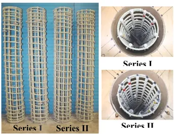
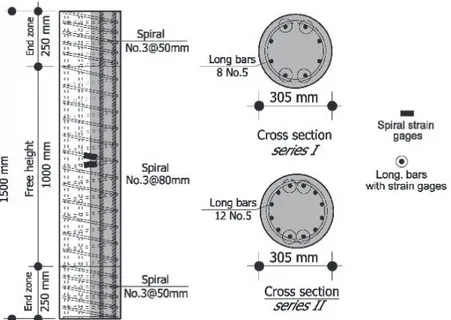
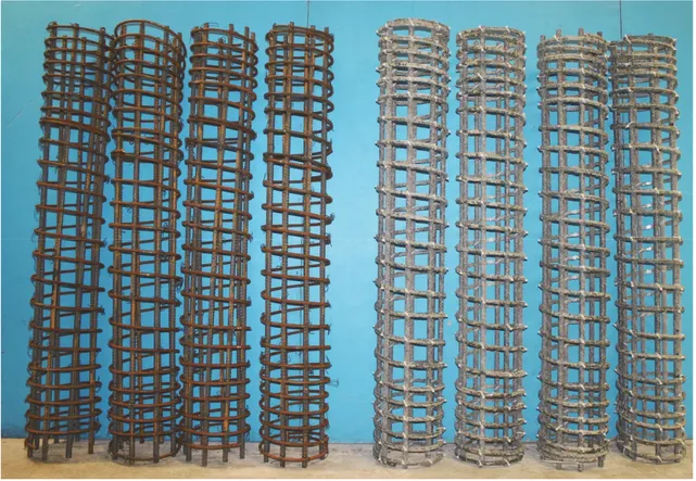
Figure 3.1– Samples of the assembled GFRP cages and cross sections (series I and II) 47 Figure 3.2– Geometry and section details (dimensions in mm) (Note: 1 mm = 0.0394 in) 48
Figure 3.3– Test setup for eccentric columns 48
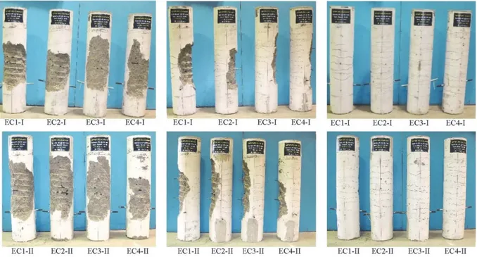
Figure 3.4– Different views of failure modes of the eccentric columns 50
Figure 3.5– Load versus axial displacement (Series I) 53
Figure 3.6– Load versus axial displacement (Series II) 54
Figure 3.7– Load versus lateral mid-height displacement (Series I) 55 Figure 3.8– Load versus lateral mid-height displacement (Series II) 55
Figure 3.9– Load versus longitudinal-bar strain (Series I) 57
Figure 3.10– Load versus longitudinal-bar strain (Series II) 57
Figure 3.11– Load versus concrete strain on the compression side 59
Figure 3.12– Effect of eccentricity-to-diameter ratio 61
Figure 3.13– Normalized interaction diagrams (Series I) 62
Figure 3.14– Normalized interaction diagrams (Series II) 62
Figure 3.15– Comparison of different concepts of the normalized interaction diagrams
(Series I) 65
Figure 3.16– Comparison of different concepts of the normalized interaction diagrams
(Series II) 66
Figure 4.1– Overview of the typical assembled steel and CFRP cages 74 Figure 4.2– Column geometry, reinforcement details, and internal instrumentation 76
Figure 4.3– Test setup 77
Figure 4.6– Load versus axial displacement at specimen centerline 81
Figure 4.7– Load versus mid-height deflection 82
Figure 4.8– Failure mode of C-25: (a) tension side; (b) side view; (c) compression side; (d
and e) close views 83
Figure 4.9– Failure modes of C-50 and C-100: (a) C-50 side view; (b) C-50 compression
side; (c) C-100 side view; (d) C-100 compression side 84
Figure 4.10– Failure mode of C-200: (a) tension side; (b) side view; (c) compression side;
(d and e) close views 85
Figure 4.11– Load versus longitudinal-bar strain 87
Figure 4.12–Experimental normalized interaction diagrams for CFRP- and steel-RC columns 91 Figure 4.13– Proposed sectional analysis for CFRP-RC columns: (a) strain compatibility;
(b) generalized stress block; (c) equivalent rectangular stress block (ERSB); (d) bar tension forces; (e) bar compression forces; (f) nominal eccentric axial
force 94
Figure 4.14– Properties of concrete compression circular segment 94 Figure 4.15– Comparison between theoretical interaction diagrams and experimental
results (D=305 mm and r/R =0.77) 95
Figure 4.16– Theoretical interaction diagrams (D=305mm and r/R=0.77): (a) ignoring the contribution of the CFRP bars in compression; and (b) considering the
contribution of CFRP bars in compression 98
Figure 5.1– Stress–strain relationship for steel and commercial GFRP bars 104 Figure 5.2– Details, column dimensions, and overview of GFRP cages with discrete hoops.
108 Figure 5.3– Test setup and failure mode of column specimens: (a) Eccentrically loaded
specimens and (b) concentrically loaded specimens 113
Figure 5.4– Lateral deflection response (P-∆) for the eccentrically loaded specimens 114 Figure 5.5– Surface concrete strain response (P-εc) for the eccentrically loaded specimens 115
Figure 5.6– Bar strain response (P-εbar) for the eccentrically loaded specimens 116
Figure 5.7– Hoop strain response (P- εhoop) for the eccentrically loaded specimens 118
Figure 5.8– Proposed section analysis based on ERSB 120
Figure 5.9– Predicted normalized interaction diagram (Kn- Rn) in comparison with test results
125 Figure 5.10– Pn - Mn interaction diagrams for scenario 1 (EFc/EFt=1) 127
Figure 5.11– Pn - Mn interaction diagrams for scenario 4 (EFc/EFt=0) 128
Figure 5.12– Impact of increasing the mechanical properties of GFRP bars 129 Figure 5.13– Impact of increasing longitudinal reinforcement ratio more than 1% for
scenario 1 130
Figure 5.14– Impact of concrete strength for scenario 1 131
Figure 5.15– Impact of concrete strength for scenario 4 131
Figure 5.16– Impact of ignoring GFRP bar contribution in compression 132 Figure 6.1– Samples of the GFRP bars and spirals used in this study 140 Figure 6.2– Fabrication and preparation of columns specimens: (a) overview of
reinforcement detail for Series A; (b) overview of reinforcement detail for
xvii Figure 6.3– Instrumentation and test setup for eccentrically loaded column specimens 145 Figure 6.4– Failure mode of the concentrically loaded columns: (a and d) elevations; (b
and c) close views 146
Figure 6.5– Failure modes of the eccentrically loaded columns (series A) 150 Figure 6.6– Load versus axial displacement at specimen centerline 153
Figure 6.7– Load versus lateral midheight displacement 154
Figure 6.8– Load versus longitudinal-bar strain 155
Figure 6.9– Load versus concrete strain on the compression side 160 Figure 6.10– Normalized interaction diagrams based on the experimental results, load
path, and strain gradient 162
Figure 6.11– Comparison of different concepts of the normalized interaction diagrams 164
Figure 7.1– CFRP reinforcement (bars and spirals) 174
Figure 7.2– CFRP- and steel-RHSC columns inside the Sonotubes and formwork; cross sections of (a) formwork and Sonotubes, (b) CFRP cage, and (c) steel cage. 177 Figure 7.3– Test setup and instrumentations (structural lab, University of Sherbrooke) 178
Figure 7.4– Failure modes 180
Figure 7.5– Load versus concrete strain on the compression side 181
Figure 7.6– Load versus axial displacement 185
Figure 7.7– Load versus lateral mid-height displacement 185
Figure 7.8– Load versus outermost bar strain at mid-height 186
Figure 7.9– Experimental normalized interaction diagrams for CFRP- and steel-RHSC
columns (strength factors set to unity) 190
Figure 7.10– Plane sectional analysis for CFRP-RHSC columns 194
Figure 7.11– Comparison between predicted interaction diagrams and experimental
results (D=305 mm and r/R =0.77) 196
Figure 7.12– Parametric study of the interaction diagrams of the circular CFRP-RHSC
columns 198
Figure 8.1– Analysis of rectangular steel-RC specimens 203
Figure 8.2– Geometry and reinforcement details of the tested groups 210 Figure 8.3– General behavior of test specimens at different levels of eccentricity 213
Figure 8.4– Analysis of the GFRP-RC circular sections 213
Figure 8.5– Concrete segment 214
Figure 8.6– ERSB parameter product α1β1 at different levels of eccentricity for the
eccentrically loaded GFRP-RC specimens 216
Figure 8.7– Influence of concrete strength on normalized axial strength at different
levels of eccentricity 217
Figure 8.8– Side view of HSC-GFRP-RC specimens confined with GFRP hoops at
different levels of eccentricity at the end of the test 219 Figure 8.9– Predicted versus experimental normalized axial force for Group V 222 Figure 8.10– Predicted versus experimental normalized axial force for Group II 224 Figure 8.11– Predicted versus experimental normalized axial force for Group III 225 Figure 8.12– Predicted versus experimental normalized axial force for Group IV 226 Figure 8.13– Predicted versus experimental normalized axial force for all GFRP-RC
Figure 9.1– Stress-strain relationships of FRP reinforcing bars 235 Figure 9.2– Stress and strain profiles of circular FRP-RC cross section 242 Figure 9.3– A schematic flowchart for elastic second-order M-ψ analysis 243 Figure 9.4– Comparison of Experimental and Analytical M-ψ for Series I 244 Figure 9.5– Comparison of Experimental and Analytical M-ψ for Series II 245 Figure 9.6– Comparison of Experimental and Analytical M-ψ for Series III 248 Figure 9.7– Comparison of Experimental and Analytical M-ψ for Series IV 249 Figure 9.8– Comparison of Experimental and Analytical M-ψ for Series V 250 Figure 9.9– Influence of e/D and P/Po on EIsec/EIg for specimens in series I 256
Figure 9.10– Influence of e/D and P/Po on EIsec/EIg for specimens in series II 256
Figure 9.11– Influence of e/D and P/Po on EIsec/EIg for specimens in series III 257
Figure 9.12– Influence of e/D and P/Po on EIsec/EIg for specimens in series IV 257
Figure 9.13– Influence of e/D and P/Po on EIsec/EIg for specimens in series V 257
Figure 9.14– Flexural stiffness of FRP-RC beam columns as a function of eccentricity at
service loads (experimental results) 259
Figure 9.15– Flexural stiffness of FRP-RC beam columns as a function of eccentricity at
ultimate loads (experimental results) 260
Figure 9.16– Proposed flexural stiffness of GFRP-RC columns (P/Po ≥0.10) 265
List of Tables
Table 3.1 – Mechanical properties of the GFRP reinforcement 45
Table 3.2 – Test matrix and specimen details 46
Table 4.1 – Mechanical properties of the CFRP and Steel reinforcement 73
Table 4.2 – Specimen details and summary of test results 75
Table 5.1 – Mechanical properties of the GFRP reinforcement 108
Table 5.2 – Specimen details and summary of test results 109
Table 6.1 – Mechanical properties of the GFRP reinforcement 140
Table 6.2 – Test matrix, specimen details, and test results 141
Table 6.3 – Comparison between the Experimental and Predicted Results 165 Table 7.1 – Mechanical properties of CFRP and steel reinforcement 175 Table 7.2 – Specimen details, lateral displacement, and strength 176
Table 8.1 – Test matrix, specimen details, and test results 211
Table 8.2 – Mechanical properties of the glass-FRP and steel bars 212
Table 9.1 – Test matrix, specimen details, and test results 233
Table 9.2 – Mechanical properties of the glass- and carbon-FRP bars 234 Table 9.3 – Comparison of EIe for FRP-RC beam columns at service loads (Ps /Po ≥0.10) 262
Table 9.4 – Comparison of EIe for FRP-RC beam columns at service loads (Ps /Po <0.10) 262
Table 9.5 – Comparison of EIe for FRP-RC beam columns at ultimate loads (Pu /Po ≥0.10) 264
CHAPTER 1
I
NTRODUCTION
1.1
General Background
Circular reinforced-concrete (RC) elements have been frequently used in civil-engineering projects, especially in bridge pier columns and pile applications such as pile walls, pile foundations, and quay walls. These sections are used to resist vertical loads (such as traffic) and lateral loads (such as wind load, lateral shock, braking force, and lateral earth pressure.) Due to the live load cases, these sections are susceptible to potential eccentric compression. The design should, therefore, include the axial compression and the induced bending moments.
Aggressive climate and environmental changes stimulate the manufacturing of a corrosion-free material. Past years have seen valuable research work and widespread applications of concrete elements having fiber-reinforced polymer (FRP) reinforcement. The manufacturing process and quality control of FRP rebar has also developed over the first generation produced since 1990s. The limited research conducted on the first generation demonstrated conflictions of FRP reinforcement regarding their compression behavior. ACI 440.1R (2006) had, therefore, prohibited using FRP reinforcement either in columns or as compression reinforcement in flexural members. Recently, few tests were conducted on columns reinforced with FRP bars (FRP-RC columns) in which their findings demonstrated the feasibility of using FRP reinforcement in columns. Consequently, FRP reinforcement is allowed in the current version of ACI 440.1R (2015) provided that their contribution in compression be neglected.
This research intended to originally examine the performance of FRP reinforcement in columns/piles under eccentric compression. The integration of such exceptional reinforcement with high-strength concrete (HSC) was also introduced for achieving better strength and
1.2
Objectives and Scopes
This research originally discussed the behavior of FRP reinforcement in circular full-scale concrete columns/piles under eccentric compression. The performance of FRP rebar and spirals, as an alternative reinforcement, was compared to steel. The interaction diagrams of the tested FRP-RC specimens were analytically developed in the same manner as steel-RC members, with some assumptions. The research also discussed the issue of compression contribution of FRP rebar in the light of the data provided by the ACI 440.1R (2015), in which recommendations were drawn. In addition, the design of FRP-RC having HSC by equivalent rectangular stress block (ERSB) parameters was in review and assessment. Furthermore, the research addressed the estimation of stiffness for structural analysis and design purposes.
The general objective of this study is:
Addressing the feasibility of FRP bars in eccentric columns and proposing design provisions and recommendations for the North-American’ codes.
The following points summarized the specific objectives:
1. Investigating the behavior and failure mode mechanisms of GFRP-RC and CFRP-RC columns subjected to combined flexural moment and compression load.
2. Developing complete interaction diagrams for GFRP- and CFRP-RC members experimentally.
3. Correlating strength predictions with the experimental results yielded by several ERSBs and hence proposing necessary modifications to provide better predictions.
4. Determining the effective stiffness of the tested specimens, compared with the available expressions, and hence proposing new expressions for better estimations.
1.3 Methodology 23
1.3
Methodology
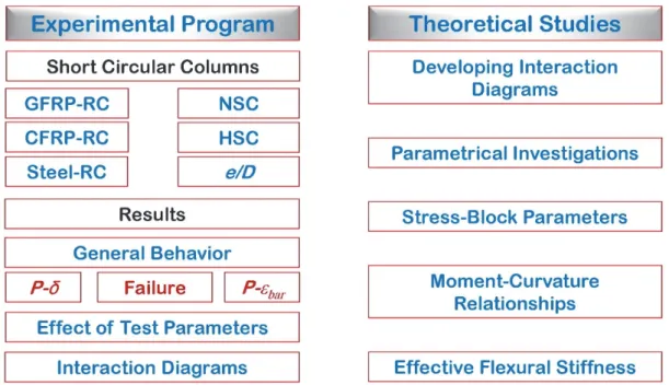
To achieve the above-described objectives, a research plan including experimental program and theoretical studies was conducted. The experimental program included testing of full-scale circular members reinforced with glass and carbon FRP as well as steel reinforcement. The results were discussed in terms of general behavior, effect of test parameters, and interaction diagrams. On the other side, theoretical studies were prepared to analytically develop the interaction diagrams of the tested specimens along with parametrical investigation. The stress block parameters of HSC members were also investigated. Moment - curvature relationships were developed using through an analytical model to predict and propose expressions for the effective stiffness. The following flow chart summarized the methodology prepared for this work.
1.4
Thesis organization
The thesis first begins commonly with a short review in Chapter 2 of presenting pertinent studies to this work in a chronological order.
Chapter 3 (1st article) presents the results of an experimental investigation on the eccentric
behavior of circular GFRP-RC column. The axial force–moment interaction diagrams were predicted based on the principles of strain compatibility and internal force equilibrium and following the recommendations of the available design standards/guidelines and recent research work on GFRP-RC columns.
Chapter 4 (2nd article) presents test results of an experimental program to investigate the
structural performance of circular concrete columns reinforced with carbon-FRP (CFRP) bars and spirals. Based on the test results, a detailed sectional analysis and plane section analysis were then conducted. Furthermore, a comprehensive parametric investigation was performed to generate numerous nominal axial force-bending moment interaction diagrams.
Chapter 5 (3rd article) presented a state-of-art review on the compressive-strength contribution
of GFRP reinforcement. The lowest and highest bounds of the mechanical properties of GFRP reinforcement reported in the ACI 440.1R (2015) were included in analytical study employing different concrete strengths and reinforcement ratios to develop sets of axial force–bending moment interaction diagrams and indicative guide charts. In addition, the minimum GFRP longitudinal reinforcement ratio to prevent tension failure (GFRP-bar rupture) was investigated.
Chapter 6 (4th article) investigated experimentally and analytically the feasibility of HSC in
circular GFRP-RC columns under concentric and eccentric loading. The axial force–moment interaction diagrams were predicted in accordance with the recommendations in the available design standards.
Chapter 7 (5th article) extended the investigation to integrate HSC in columns reinforced
totally with CFRP bars and spirals. comprehensive study was then conducted based on the test results and plane section theory. Based on this study, the axial and flexural capacity of
CFRP-1.4 Thesis organization 25
RC with HSC columns can be reasonably predicted using plane sectional analysis. Furthermore, a detailed parametric investigation was conducted to generate numerous axial force–flexural moment (P-M) interaction diagrams.
Chapter 8 (6th article) initiated an early attempt to investigate the applicability of several
equivalent rectangular stress blocks (ERSB)s proposed by different associations to predict the strength of HSC-GFRP-RC specimens subjected to combined flexural and compression loads. Extensive analyses were integrated into the test results to investigate the impact of each test parameter on ERSB parameters. Modified expressions of the ERSB given in ACI 440.1R and CSA S806 were developed.
Chapter 9 (7th and 8th articles) presents an analytical modeling to predict the moment-curvature
responses of the tested specimens. Two models for unconfined and confined concrete are examined in this study, based on strain-compatibility and force-equilibrium. A procedure for second-order analysis was described and used in this model to consider the second-order effect. The effective stiffness of the tested specimens was then evaluated and discussed. The stiffness results were calculated using different approaches in the literature and compared with those obtained based on the experimental database. Proposed expressions were eventually developed and validated against the experimental results at service and ultimate levels.
The last Chapter of the thesis, Chapter 10, presents some detailed conclusions of the results obtained from the experiments and analyses with respect to observations and highlights discussed throughout the thesis in addition to recommendations for future work.
CHAPTER 2
L
ITERATURE REVIEW
2.1
Background on Materials
2.1.1
FRP reinforcement
Investigations of members subjected to axial and flexure have been in spot-interest since the beginning of the 20th century using normal and high-strength concrete. Most of these efforts were concerned with the traditional steel reinforcement. By the 1950s, the FRPs were first investigated for structural use, until they have been considered for structural engineering applications by the 1970. Since this time, few investigations were, however, conducted on the behavior of columns reinforced with FRP bars and spirals/hoops. More details about the historical review and various properties of FRP reinforcement can be found in other publications (Hadhood 2015; ACI 440.1R 2015; AASHTO 2009). The following part presents an elaborate review of some studies pertinent to the subject under investigation.
2.2
Behavior of High Strength Concrete
The definition of High strength concrete (HSC) varies with countries and time, it has been changed over the years. For instance, in 1992concrete with a compressive strength of 41 MPa was considered as high strength (ACI 363R 1992). Later, it has been changed to 55 MPa in the ACI 363R (2010). Today, compressive strengths approaching 138 MPa have been produced for cast-in-place buildings. In this study, the concrete strength of 70 MPa is considered HSC.
placing, and quality control methods. It was observed that decreasing either the water-to-cement ratio or the aggregate size can achieve a perceptible increase in the concrete strength
(ACI 363R 1992). For example, a water-to-cement ratio of 1.2 by volume which is equivalent to 0.4 by mass is needed to hydrate all the cement particles in a concrete mixture (Mahter and Hime 2002). It was also experienced that adding mineral admixtures such as silica fume and fly-ash to the concrete mixture enhances the chemical reaction of the mixture and fills the spaces between cement grains. On the other hand, the using of chemical admixtures has become a substantial solution to overcome the workability problems. Laboratory researchers using special materials and processes have achieved concrete mixtures with compressive strengths more than 116,000 psi (800 MPa).
The failure mechanism of any concrete mixture depends on the stiffness of its ingredients and the interface between the aggregate and the cement paste. For HSC, it was observed that cement pastes and the interface between cement pastes and the aggregates are generally stronger than the aggregate itself. Thus, the strength of the aggregate mainly controls the value of the compressive strength. While for NSC, the cement paste is generally the main controller of the concrete compressive strength. Furthermore, HSC has a sudden explosive manner when fails unlike NSC which gradually fails; one of the most significant characteristic differences between NSC and HSC is the failure mode at ultimate. The shape of the ascending branch of concrete stress-strain curve becomes more linear and steeper as the compressive strength increases, and the slope of the descending part also becomes steeper. At loading HSC, two stages generally are observed, the linear elastic stage which induces between 70-85% of the peak load and curved plastic stage where the load increases ending by a sudden failure.
HSC has been increasing due to its advantages over NSC. HSC usually includes ingredients with high resistant to chloride damage and other chemical attacks. It’s highly durable, due to its low permeability, and hence requires low maintenance cost. HSC allows the designers to produce minimized structural sections, due to the superior performance, providing the serviceability limits are satisfied. HSC is favourable in concrete bridges and high-rise buildings especially in columns. Numerous buildings and bridges have been constructed using HSC. For building examples, Taipei 101 in Taiwan 2004, Brillia tower in Tokyo 2004, 505 5th Avenue in New York 2004, and Bay Adelaide Center in Toronto 1991. While, for bridge examples,
2.3 Research on steel-RC columns 29
State route 920 over I-75 in Georgia 2002, Federation Bridge Prince Edward Island in Canada 1997, and Portneuf in Quebec 1992.
2.3
Research on steel-RC columns
Research on columns with NSC initiated early by the 1900s in which the basic concepts were first introduced. Experimental and analytical Investigations contributed to produce the first version of guidelines for the design of sections under axial or combined flexure-axial loading. These Investigations are also considered main references for future research.
Hognestad (1952) tested 120 steel-RC column specimens with NSC of which 90 were 10-in. (250 mm) square tied columns with 1.46% to 4.8% percent, and 30 were 10-in. (300 mm) cylindrical spiral columns with 4.25% longitudinal reinforcement. The specimens’ total heights varied between 1900 mm for rectangular specimens and 2200 mm for circular specimens, in which the testing regions kept constant at 1270 mm for all. The eccentricity-to-lateral dimension varied between 0 to 1.25. Load was applied through "knife-edges" at the top and bottom support of all columns except the concentrically loaded spiral columns which were tested with flat ends. The test results mainly showed two modes of failure, compression failures and tension failures. The compression failures were characterized by crushing of the concrete at the compression face while stresses in the tension reinforcement were less than the yield point. Tension failures, on the other hand, were characterized by yielding in the tension reinforcement followed by large deformations and considerable movements of the neutral axis before crushing of the concrete took place. Based on past studies and phenomena observed in the present tests, a general inelastic flexural theory was developed of which the behavior of the test columns as well as the ultimate loads could be predicted. This theory served as an important basis in developing approximations suitable for design and extending the range of such approximations beyond the limitations of existing test data. The joint ACI-ASCE committee was formed in 1952 on a goal of ultimate strength design. It was hence desirable to improve and extend the knowledge regarding the stress block. Hognestad et al. (1955) developed a test method of unreinforced concrete specimens to maintain the neutral-axis at a face of the test
specimen throughout the test by applying a major and a minor load at two different positions. Thereby complications resulting from tensile stresses in the concrete were eliminated. The average compressive stress in the concrete then always equaled the total axial load divided by the section area, and the centroid of the stress block coincided with the eccentricity of the total applied load. The setup has been known now as “Hognestad setup”. The flexural stress-strain relationship of the concrete was eventually determined from zero load to failure by numerical differentiation.
Figure 2.1– Test method developed by Hognestad et al. (1955)
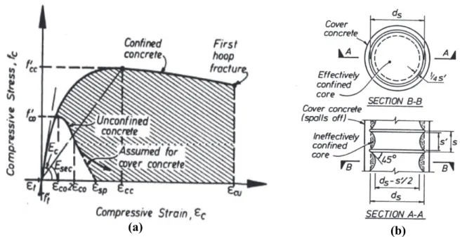
Mander et al. (1988a and 1988b) presented an important reference of a stress-strain model for confined concrete through their experimental and analytical investigations. The experimental program included testing 31 nearly full-size at axial loading. The tested specimens were all reinforced, of circular, square, or rectangular wall cross section, and containing various arrangements of reinforcement. The longitudinal stress-strain behavior of the confined concrete was measured and compared with that predicted by a previously derived stress-strain model allowing the effects of various configurations of transverse confining reinforcement, cyclic loading, and strain rate to be examined.
2.3 Research on steel-RC columns 31
Figure 2.2– (a) Stress-Strain Model Proposed for Monotonic Loading of Confined and
Unconfined Concrete; (b) Effectively Confined Core for Circular Hoop Reinforcement (Mander et al. 1988b)
Sheikh and Toklucu (1993) conducted an experimental program to evaluate the effects of different variables, such as the amount, spacing of spiral steel and specimen size, on the behavior of confined concrete, and to evaluate the requirements of ACI 318 (1989) related to the minimum volumetric ratio and maximum spacing of spiral steel. A total of 27 specimens consisting of nine each of 14-in. (356-mm), 10-in. (254-mm), and 8-in. (203-mm) diameter columns reinforced with spirals or hoops and longitudinal steel were tested under monotonic concentric compression. They reported that strength and ductility of confined concrete increased with an increase in the amount of lateral steel, the strength enhancement being much less sensitive than ductility. The 80-mm limit on spacing appears unnecessarily restrictive for large columns. In addition, the they claimed the requirement of a minimum of six bars to be unnecessary and difficult to meet in small columns provided appropriate proper confining. They also examined the size effect in which columns with similar reinforcement ratio and similar spiral/hoop spacing-to-diameter ratio behaved similarly, irrespective of their sizes. The performance of circular hoops was also checked in this study where it was efficient in confining concrete as spirals in three different sizes of columns. They eventually found that well-confined
columns achieved increases in concrete strength due to confinement in range between 2.1 and 4.0 times the lateral pressure.
Ibrahim and MacGregor (1996a, 1996b and 1997) tested 20 RC columns under eccentric loads to study the flexural behavior of rectangular and triangular compression zones of HSC and UHSC. The specimens had different concrete strengths and confinement steel arrangements and were tested under the action of two independent loads, as previously described in the research of Hognestad (1955). The results revealed that the stress-strain curves of the HSC specimens had short descending branches, while the curves of the Ultra-HSC (UHSC) specimens did not have descending branches. They found that a cylinder stress-strain curve with a peak stress equal to
0.9
f
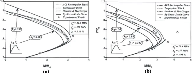
c' could conservatively represent the stress-strain curve of an eccentrically loaded column in the ascending part of the loading history before spalling of the concrete cover. In addition, the shape of the compression zone was an important parameter in determining the ductility of the section. The triangular compression zones exhibited more ductile behavior than the rectangular compression zones. Furthermore, they compared the results on 90 tests of concentrically and 94 tests of eccentrically loaded columns made from NSC, HSC, and UHSC to compare their strength results with predicted results using the ACI rectangular stress block (ACI 318 1995). This comparison indicated the ACI was not conservative for HSC column sections that failed in compression. New equations for the parameters that define the ACI rectangular stress block were suggested and compared to tests.Lee and Son (2000) tested 32 column specimens under monotonically increasing axial load with eccentricity. The concrete compressive strength varied from 34.9 to 92.3 MPa and the longitudinal steel ratios were between 1.13 and 5.51%. Test results were compared with analytical column strengths by use of the ACI rectangular stress block, the trapezoidal stress block, the modified rectangular stress block, and moment-curvature analysis. They observed during tests that the concrete cover spalling zone tended to be larger as concrete compressive strength and steel ratio increased and as slenderness ratio and initial eccentricity decreased. The calculated strengths in compression control region showed significant differences between the ACI rectangular, trapezoidal, and modified rectangular stress blocks as well ass with the test values. The ACI rectangular stress block (ACI 318 1995) calculated higher column strengths than the other two stress blocks, and resulted in an overestimate of column strengths
2.4 Research on FRP-RC columns 33
for the lightly reinforced high-strength column specimens. They eventually recognized that the analytical column strengths by moment-curvature analyses are highly affected by k3 values of
the concrete stress-strain curve and suggested further research on the k3 value and column size
effect may be needed for practical design, as shown in Fig. 2.3.
Figure 2.3– Normalized strength of low-strength concrete columns: (a) L series with NSC
and (b) H series with HSC (Lee and Son 2000)
2.4
Research on FRP-RC columns
Paramanantham (1993) initiated the first study addressing columns by testing 17 square columns with slenderness kl/r =30, this study was a part of his M.sc dissertation. All columns had the same size of 200 mm sides and 1800 mm total height with end-haunches and reinforced longitudinally with 2% GFRP bars. The lateral ties provided by #3 each 100 mm. The ultimate tensile strength and tensile Young’s modulus varied between 550 MPa to 590 MPa and between 38 GPa to 41 GPa, respectively. It should be noted that GFRP bars produced today by different companies had higher tensile strengths than these values. All specimens failed due to crushing of concrete. Interaction diagram of the tested specimens were developed and compared with predictions.
Mirmiran (1998) developed an important analytical model to investigate the lengths effects on FRP-RC concrete columns. The model considered the constitutive properties of materials including concrete, steel and FRP rebar. The compressive behaviour of concrete was modelled by the unconfined second-degree parabola proposed by Hognestad (1952), while the tensile properties was ignored. A tri-linear strain hardening model was incorporated for steel rebar while a linear-elastic response was considered for FRP rebar until failure. The variables included the compressive-to-tensile strength ratio of FRP rebar. The second-order effect was also implemented in the model by integrating deflections over the length of the column. The model was validated with 4 square CFRP-RC columns with 152 mm sides. It should be noted that the tensile strength and tensile Young’s modulus were: 1345 MPa and 64.8 GPa for Aramid-FRP (AFRP) rebar; 500 MPa and 29.65 GPa for GFRP rebar; 1000 MPa and 96.5 GPa for CFRP rebar. These values are quite smaller than todays’ products. In addition, the properties of the AFRP used in his study is quite similar to the high-modulus (HM) GFRP rebar produced by Pultral (2012). His findings included a comparison of different reinforcement through developing several interaction diagrams, as shown in Fig. 2.4.
Figure 2.4– Strength Interaction Diagrams for various Reinforcement Materials (Mirmiran 1998)
2.4 Research on FRP-RC columns 35
The results of this study may be, however, considered invalid for applications today due to the differences of FRP materials produced today. Figure 2.5 shows a family of interaction diagrams including the slenderness effect.
Figure 2.5– Slender Column Interaction Diagrams for Different Reinforcement Rebar: (a)
glass, (b) aramid, (c) carbon, and (d) steel (Mirmiran 1998)
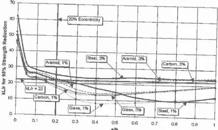
The effect of reinforcement ratio and material were presented in the form of Figs 2.6 and 2.7. Figure 2.6 depicts the strength reduction as a function of eccentricity ratios. ACI 318 (1995) allowed a 5% reduction of strength before slenderness effects are considered. Figure 2.7 shows the plots of slenderness ratios for a 5% strength reduction as a function of eccentricity ratios. He concluded, based on these results, that slenderness limits shall be reduced by 5%, 15% and 22% for aramid, carbon and glass rebar, respectively, if the minimum reinforcement ratio is held at 1%. Later, Mirmiran et al. (2001) recommended, based on their parametric studies, that the current slenderness limit of 22 for steel-RC columns bent in single curvature be reduced to
(a) (b)
17 for FRP-RC columns. They claimed also that the variation in tensile strength of typical FRP bars does not affect slenderness of RC columns. Choo et al. (2006a) conducted a similar analytical study as a part of Choo’s Ph.D. dissertation with similar findings. They extended their study by developing sets of charts to identify the minimum required reinforcement FRP ratio to prevent rupturing of bars (Choo et al. 2006b).
Figure 2.6– Effect of reinforcement ratio and material on strength reduction (Mirmiran 1998)
Figure 2.7– Effect of reinforcement ratio and material on slenderness limit (Mirmiran 1998)
Afifi (2013c) conducted experimental and analytical programs on circular concrete columns reinforced with FRP bars and spirals under concentric axial loading, as a part of his Ph.D. dissertation. The current study represents an extension to his study among a mother project targeting the analysis and design of FRP-RC members. Throughout his work in the dissertation,
2.4 Research on FRP-RC columns 37
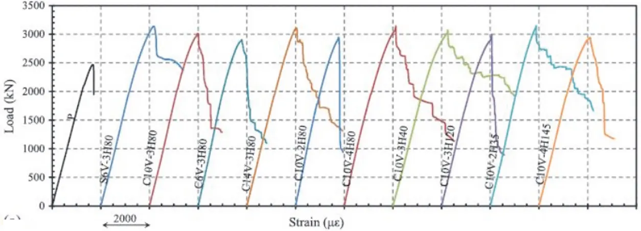
several findings were attained, and came into sight by several Publications (Afifi et al. 2013a, 2013b, 2014, and 2015; Mohamed et al. 2014). The experimental program includes testing of 27 circular concrete columns having 300 mm diameter and 1500 mm height. The testing variables were the type of reinforcement (None, steel, GFRP or CFRP); longitudinal reinforcement ratio; volumetric ratios, diameters, and spacing of spiral reinforcement; confinement type (spirals vs. hoops); and lap length of hoops. The testing results revealed that FRP bars were effective in resisting compression until after crushing of concrete, and contributed on average 8% and 13% of column capacity for GFRP and CFRP RC specimens, respectively. The authors reported that ignoring the contribution of FRP longitudinal bars in the CSA S806 (2012) design equation underestimated the maximum capacity of the tested specimens. They suggested a modification to the design equation to accurately predict the ultimate load capacities of FRP RC columns. Figure 2.8 summarize the effect of the test parameters presented in Afifi et al. (2013b) addressing the behavior of CFRP-RC specimens. It was observed from this figure that the steel-RC and CFRP-RC specimens with similar values of axial stiffness (EA) achieved similar strengths (S6C-3H80 and C10V-3H80). The second observation is that CFRP-RC specimens had limited post-peak behavior even with high confinement.
Figure 2.8– Effect of test parameters of the tested CFRP-RC specimens on load-strain curves
The authors reported that the failure of CFRP bars was in the form of breaking the bars into many small pieces in the test region. They described the failure to be different than the rupture failure under tension load, which often showed randomly fracture carbon. These observations were consistent with the test results by other study obtained on CFRP-RC columns (Sharbatdar 2003). Figure 2.9 presents a clear comparison of the test specimens in terms of test parameters.
Figure 2.9a revealed that steel-RC and GFRP-RC specimens behaved similarly and achieved similar strengths as well as similar post-peak response.
Figure 2.9– Effect of test parameters on the load–strain curves of the tested GFRP-RC
specimens: (a) type of reinforcement; (b) longitudinal reinforcement ratio; (c) GFRP spiral spacing; (d) stirrup diameter; (e) transverse size/spacing configuration (Afifi et al. 2013a)
Figure 2.9b revealed that increasing reinforcement ratio slightly increased the maximum load with enhanced stiffness. The post-peak enhanced as closer as the spirals spaced, as shown in
2.4 Research on FRP-RC columns 39
specimens, as shown in Fig. 2.9d. The performance of spirals no. 3 and no.4 was quite similar. Proposed equations and confinement model were also presented to predict the axial stress-strain behavior of FRP RC columns confined by FRP spirals or hoops. The model modified Mander’s model based on the test results.
Several studies have been published recently by a research group in University of Wollongong on the behavior of GFRP-RC columns under axial and/or eccentric loading (Hadi and Youssef 2016; Hadi et al. 2016 and 2017; Karim et al. 2016, 2017a, 2017b). These studies include experimental and analytical investigations of various parameters. The experimental program used square cross section of 210 mm sides and 800 mm height and/or circular sections of diameter 205 mm and height 800 mm. The specimens tested under concentric loading; eccentric loading of 25 mm and 50 mm; and/or two-point loading flexure. The test variables were the type of reinforcement (steel vs. GFRP); external confinement or none; internal reinforcement or none; normal concrete or fiber-reinforced concrete. The analytical program included developing interaction diagrams; parametric studies; estimation of ductility.
Their concentric GFRP-RC specimens exhibited second peak points indicating proper confinement, provided by helices spaced each 30 mm or 60 mm. The closely spaced specimen exhibited, however, higher second peak than the other (Hadi et al. 2016). They reported that reducing the GFRP helices pitch from 60 to 30 mm led to an improvement in the performance of the GFRP-RC specimens in terms of load-carrying capacity, bending moment, and ductility. They also reported that the contribution of the longitudinal steel bars in the load carrying capacity of the concentric column specimens was about twice the contribution of the longitudinal GFRP bars, whereas the ductility of the GFRP-RC column specimens was slightly greater than the ductility of the reference steel-RC column specimens under different loading conditions. Karim et al. 2017 addressed the limits of FRP reinforcement in members with different cross sections and different bar arrangements. The study findings include proposing an equation for calculating the deformability factor (DF) using integration of the concrete layers through Popovics’s model (1973), in which the DF is a ratio of the product of moment and curvature at ultimate to the product of moment and curvature at serviceability limit state.
CHAPTER 3
Failure Envelope of Circular Concrete Columns
Reinforced with GFRP Bars and Spirals
(ACI structural Journal, V. 114-6, in press)
Abstract
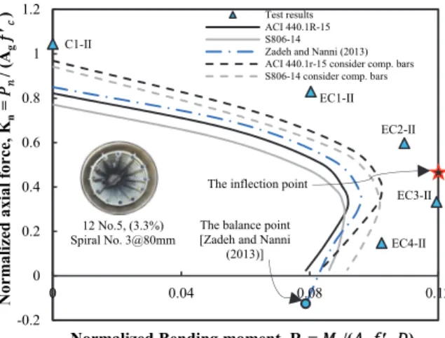
This paper presents the results of an experimental investigation on the eccentric behavior of 10 circular concrete columns reinforced with glass-fiber-reinforced-polymer (GFRP) bars and spirals. The columns measured 1500 mm (60 in.) in length and 305 mm in diameter (12 in.). The test variables were the eccentricity-to-diameter ratio and the longitudinal-reinforcement ratio. The columns were subjected to predesigned different levels of eccentricities to develop the failure envelope (axial load–moment interaction diagram). Compression failure due to concrete crushing controlled the ultimate capacity of specimens tested under low eccentric loading. Flexural–tension failure initiated in specimens tested under high eccentric loading, however, resulted from large axial and lateral deformations and cracks on the tension side until a secondary compression failure occurred due to the strain limitations in concrete and degradation of the concrete compressive block.
The axial force–moment interaction diagrams were predicted based on the principles of strain compatibility and internal force equilibrium and following the recommendations of the available design standards/guidelines and recent research work on GFRP-RC columns. The analysis results revealed that ignoring the contribution of GFRP bars in compression conservatively underestimated the axial–flexural capacity of test specimens.