2009 — Development of a flexible protective system for press-brakes using vision
Texte intégral
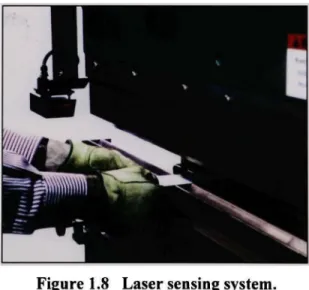
Figure


Documents relatifs
En comparaison avec le lancer de marteau, quel type d’action doit exercer le Soleil sur une planète pour l’empêcher de s’échapper dans l’espace?. (figures 1 et
1 -a – Compléter le schéma suivant avec les noms des changements d’état physique convenable ( fusion – vaporisation – solidification – liquéfaction ). 1 –b- donner le
Donner la mesure de l’angle marqué en justifiant
Par précaution, barrer l’autre figure. 1) Tracer, sur la figure A, la perpendiculaire à la surface de séparation au point I. Comment s’appelle cette droite ? ... 2) Le rayon
[r]
Une origine (point d’application) Un point où l’on souhaite mesurer la vitesse Sa direction : La droite tangente à la trajectoire au point M. Son sens : Celui
2- Déterminer l’expression de.. Déterminer la tension de sortie et tracer la caractéristique pour les circuits de la figure 4. Déduire la nature de chaque amplificateur.. Pour
Colorie la porte en bleu, la grande fenêtre en jaune, les petites fenêtres en vert et les murs en rouge. 3 - Construis la figure symétrique de la figure représentée par rapport
