HAL Id: tel-00939092
https://tel.archives-ouvertes.fr/tel-00939092
Submitted on 30 Jan 2014
HAL is a multi-disciplinary open access
archive for the deposit and dissemination of sci-entific research documents, whether they are pub-lished or not. The documents may come from teaching and research institutions in France or abroad, or from public or private research centers.
L’archive ouverte pluridisciplinaire HAL, est destinée au dépôt et à la diffusion de documents scientifiques de niveau recherche, publiés ou non, émanant des établissements d’enseignement et de recherche français ou étrangers, des laboratoires publics ou privés.
Study of mechanisms ensuring service continuity for
IKEv2 and IPsec protocols
Daniel Palomares Velasquez
To cite this version:
Daniel Palomares Velasquez. Study of mechanisms ensuring service continuity for IKEv2 and IPsec protocols. Architecture, space management. Institut National des Télécommunications, 2013. English. �NNT : 2013TELE0025�. �tel-00939092�
Sp´ecialit´e: ´
Ecole doctorale: Informatique, T´el´ecommunications et ´Electronique de Paris
Pr´esent´ee par
Daniel Palomares Velasquez
Pour obtenir le grade de
Docteur de T´el´ecom SudParis
´
Etude de M´
ecanismes Assurant la Continuit´
e de
Service de Protocoles IKEv2 et IPsec
Soutenue le 14 Novembre, 2013 No. de th`ese: 2013TELE0025
Devant le jury compos´e par:
BONNIN Jean-Marie, Professeur HDR `a T´el´ecom Bretagne Rapporteur CARLE Georg, Professeur `a Technische Universit¨at M¨unchen Rapporteur PUJOLLE Guy, Professeur `a l’Universit´e Pierre et Marie Curie - LIP6 Examinateur COMBES Jean-Michel, Docteur et Ing´enieur `a Orange Labs de France T´el´ecom R&D Examinateur MIGAULT Daniel, Docteur et Ing´enieur `a Orange Labs de France T´el´ecom R&D Examinateur LAURENT Maryline, Professeur HDR `a T´el´ecom SudParis - Departement RST Directrice de Th`ese
Specialty:
Doctoral School: Informatique, T´el´ecommunications et ´Electronique de Paris
PhD Thesis Dissertation by Daniel Palomares Velasquez
To obtain the degree of:
Doctor of T´el´ecom SudParis
Study of Mechanisms Ensuring Service Continuity
for IKEv2 and IPsec Protocols
Defense date: November 14th, 2013 No. of thesis: 2013TELE0025
Members of the jury:
BONNIN Jean-Marie, Professor HDR at T´el´ecom Bretagne Reporter CARLE Georg, Professor at Technische Universit¨at M¨unchen Reporter PUJOLLE Guy, Professor at University Pierre et Marie Curie - LIP6 Examiner COMBES Jean-Michel, Doctor and Engineer at Orange Labs of France T´el´ecom R&D Examiner MIGAULT Daniel, Doctor and Engineer at Orange Labs of France T´el´ecom R&D Examiner LAURENT Maryline, Professor HDR at T´el´ecom SudParis - Departement RST Thesis Director
First of all I would like to render thanks to every single person that help me out through all my career. Specially my parents, which are my biggest inspiration.
The first steps of this thesis were done thanks to Professor Maryline Laurent, my thesis director. I can only say thanks for her support and patience as well as for the time she has consecrate to this research.
Second, I would not be able to make this investigation without the help and supervision of Daniel Migault. I admire his capability, creativity, professionalism and enthusiasm. Throughout these years, I have learned a lot from him and I am truly grateful.
I also had the opportunity to conduct several academic projects and internships. They all have been a big source of apprenticeship to me.
I am also grateful towards Vincent Barriac, which I thank you for his investment in producing excellent quality results concerning the last part of this thesis.
These persons also helped me throughout the achievement of my thesis: Wolfgang Velasquez, Martin Willi, Jean-Michel Combes, Hendrik Hendrik, Emmanuel Herbert, Aurelien Wally, Jose Daniel Gomes, Ana Maria.
Being part of Orange has been a truly remarkable experience for my professional career, and I Thank You All.
Daniel Palomares. September 2013.
During 2012, the global mobile traffic represented 70% more than 2011. The arrival of the 4G technology introduced 19 times more traffic than non-4G sessions, and in 2013 the number of mobile-connected to the Internet exceeded the number of human beings on earth. This scenario introduces great pressure towards the Internet service providers (ISPs), which are called to ensure access to the network and maintain its QoS. At short/middle term, operators will relay on alternative access networks in order to maintain the same performance characteristics. Thus, the traffic of the clients might be offloaded from RANs to some other available access networks. However, the same security level is not ensured by those wireless access networks. Femtocells, WiFi or WiMAX (among other wireless technologies), must rely on some mechanism to secure the communications and avoid untrusted environments.
Operators are mainly using IPsec to extend a security domain over untrusted networks. This introduces new challenges in terms of performance and connectivity for IPsec. This thesis concentrates on the study of the mechanism considering to improve the IPsec protocol in terms of continuity of service.
The continuity of service, also known as resilience, becomes crucial when offloading the traffic from RANs to other access networks. This is why we first concentrate our effort in defining the protocols ensuring an IP communication: IKEv2 and IPsec. Then, we present a detailed study of the parameters needed to keep a VPN session alive, and we demonstrate that it is possible to dynamically manage a VPN session between different gateways. Some of the reasons that justify the management of VPN sessions is to provide high availability, load sharing or load balancing features for IPsec connections. These mechanisms increase the continuity of service of IPsec-based communication. For example, if for some reason a failure occurs to a security gateway, the ISP should be able to overcome this situation and to provide mechanisms to ensure continuity of service to its clients.
Some new mechanisms have recently been implemented to provide High Availability over IPsec. The open source VPN project, StrongSwan, implemented a mechanism called ClusterIP in order to create a cluster of IPsec gateways. We merged ClusterIP with our own developments in order to define two architectures: High Availability and Context Management over Mono-LAN and Multi-LAN environments. We called Mono-LAN those architectures where the cluster of security gateways is configured under a single IP address, whereas Multi-LAN concerns those architectures where different security gateways are configured with different IP addresses.
Performance measurements throughout the thesis show that transferring a VPN session between different gateways avoids re-authentication delays and reduce the amount of CPU consumption and calculation of cryptographic material. From an ISP point of view, this could be used to avoid overloaded gateways, redistribution of the load, better network performances,
vi
improvements of the QoS, etc. The idea is to allow a peer to enjoy the continuity of a service while maintaining the same security level that it was initially proposed.
1 Introduction 1
1.1 Architectures of Interest . . . 2
1.1.1 Clustering IPsec Security Gateways . . . 2
1.1.2 Offload Architectures . . . 3
1.2 VPN Service description and technical challenges . . . 7
1.2.1 High Availability of IPsec-based VPNs . . . 7
1.2.2 Traffic Management of IPsec-based VPNs . . . 8
1.3 Context Transfer is not designed for Mobility . . . 9
1.4 Related work and position of our work . . . 10
1.4.1 Position towards theoretical proposed architectures . . . 10
1.4.2 Position towards existing implementation . . . 12
1.4.3 Detailed position towards High Availability vs. Mobility scenarios . . . . 13
1.5 Contributions . . . 14
1.6 Thesis Organization . . . 16
I Security for IP Networks 17 2 Roadmap of IPsec and IKEv2 protocols 19 2.1 Security Services . . . 19
2.2 IPsec: Security Associations and Databases . . . 20
2.3 IPsec Protocols . . . 22
2.3.1 Authentication Header . . . 22
2.3.2 Encapsulation Security Payload . . . 22
2.4 Security Management: Manual Vs. IKEv2 protocol . . . 23 vii
viii Contents
2.4.1 Exchange Description: IKE SA INIT . . . 24
2.4.2 Exchange Description: IKE AUTH . . . 25
2.4.3 Authentication of IKE SA . . . 27
2.5 Clustering at the IP layer: ClusterIP . . . 28
2.6 MOBIKE - mobility extension for IKEv2 . . . 29
2.7 REDIRECT extension for IKEv2 . . . 30
2.8 Conclusion . . . 31
3 IKEv2/IPsec Context Definition 33 3.1 Introduction . . . 33
3.2 Motivation . . . 34
3.3 IKEv2/IPsec Context Detailed Description . . . 35
3.4 GET and PUT functions: Description . . . 37
3.4.1 Motivation: manage and transfer of and IKEv2/IPsec context . . . 37
3.4.2 Implementation . . . 37
3.4.3 Testbed . . . 39
3.5 Performance tests & Results . . . 40
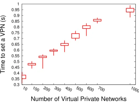
3.5.1 First Test - VPN Establishment Time . . . 40
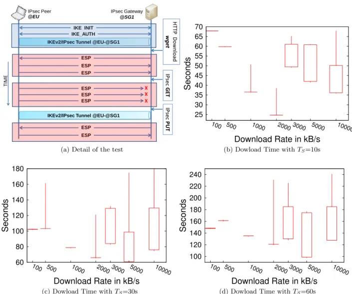
3.5.2 Second Test - GET and PUT Times . . . 41
3.5.3 Third Test - Upper-layer’s Reactivity . . . 43
3.6 How can we transfer an IKEv2/IPsec context? . . . 44
3.7 Conclusion . . . 45
II IPsec/IKEv2 Context Transfer for Mono-LAN architectures 47 4 Mono-LAN Context Transfer: ClusterIP 49 4.1 Motivations and Mono-LAN High-Availability Scenario . . . 50
4.2 Test-bed . . . 51
4.3 Position of our Work & Related Work . . . 51
4.4 IKEv2/IPsec and High Availability Constraints . . . 52
4.4.1 IKEv2/IPsec Counter Synchronization . . . 53
4.5.1 Load-Balancing Versus High-Availability Clusters . . . 56
4.5.2 ClusterIP Implementation . . . 56
4.6 StrongSwan’s ClusterIP-based HA Plugin . . . 57
4.6.1 IKE Daemon Implementation . . . 58
4.7 Performance Tests & Results . . . 60
4.7.1 Testbed description . . . 60
4.7.2 First Test - ClusterIP overhead Measurements Test . . . 61
4.7.3 Second Test - QoS on an HTTP connection . . . 63
4.7.4 Third Test - Interruption Time of an HTTP communication . . . 65
4.8 Conclusions . . . 66
5 Mono-LAN Context Transfer: Context Management 69 5.1 Motivations and Mono-LAN Context Management . . . 69
5.2 Scenarios: HA and Context Management . . . 70
5.2.1 High Availability for n gateways . . . 70
5.2.2 Context Management . . . 72
5.3 Position of our Work . . . 73
5.4 Performance Tests . . . 75
5.4.1 Testbed description and scenarios . . . 75
5.4.2 Protocols, parameters and audio streaming tools . . . 77
5.5 Performance results . . . 83
5.5.1 Results for High Availability . . . 83
5.5.2 Results for context management . . . 88
5.6 Conclusions . . . 95
III IPsec/IKEv2 Context Transfer for Multi-LAN architectures 97 6 Multi-LAN IKEv2/IPsec Context Transfer 99 6.1 Motivations . . . 99
6.2 Position of our Work . . . 100
6.2.1 Context Transfer Protocol (CXTP) . . . 100
x Contents
6.2.3 MOBIKE - IKEv2 Mobility and Multihoming Protocol . . . 101
6.3 Multi-LAN Scenario . . . 103
6.4 Proposed solution based on MOBIKE extension . . . 103
6.4.1 Implementation considerations . . . 105
6.5 Conclusions . . . 106
7 Conclusions and Future Work 109 Conclusions and Future Work 109 Appendices 113 A VLC Streaming Commands 115 A.1 Commands . . . 115
B R´esum´e ´etendu en Fran¸cais 117 B.1 R´esum´e . . . 117
B.2 Objetif de la th`ese . . . 118
B.3 Description du Service VPN et ses challenges techniques . . . 119
B.3.1 La Haute Disponibilit´e de VPNs IPsec . . . 119
B.3.2 Management de VPNs du type IPsec . . . 120
B.4 Pourquoi il y a t-il besoin d’une nouvelle solution? . . . 121
B.5 Organisation du R´esum´e . . . 122
B.6 Section 1: L’Etat de l’art . . . 123
B.7 Section 2: D´efinition du Contexte . . . 123
B.8 Section 3: Mono-LAN . . . 124
B.9 Section 4: Mono-LAN: L’haute disponibilit´e et la gestion du trafic VPN . . . 124
B.10 Section 5: Multi-LAN . . . 128
B.11 Conclusions et Perspectives . . . 131
Acronyms and Definitions 137
Bibliography 138
1.1 Clustering IPsec security gateways . . . 3
1.2 Offload Architecture: Context transfer within a same administrative domain . . . 5
1.3 Offload Architecture: Context transfer between two administrative domains . . . 6
1.4 IKEv2/IPsec context transfer scenarios . . . 8
2.1 IPsec transport mode scenarios. . . 21
2.2 IPsec tunnel mode scenarios. . . 21
2.3 IPsec Encapsulation Protocol: Athentication Header . . . 22
2.4 IPsec Encapsulation Protocol: Encapsulation Security Payload Header . . . 23
2.5 IKEv2 message exchanges, IKE INIT and IKE AUTH . . . 24
2.6 IKE SA INIT exchange details. . . 25
2.7 Detailed IKE AUTH exchange. . . 26
2.8 MOBIKE Protocol Exchanges . . . 30
2.9 REDIRECT support during IKE SA INIT . . . 30
2.10 REDIRECT exchanges . . . 31
3.1 Schema of an IKEv2/IPsec Context Transfer Mechanism in a Gateway . . . 38
3.2 Box-and-Whisker plot representation (quartiles) . . . 40
3.3 VPN Establishment Time . . . 41
3.4 Experimental IKEv2/IPsec Context Management . . . 42
3.5 Upper-layer’s Reactivity . . . 43
4.1 IKE/IPsec counters desynchronization . . . 54
4.2 Scenarios . . . 61
4.3 First Test: Download Performance Test (CPU Usage) . . . 62
4.4 First Test: Download Performance Test (time) . . . 64 xi
xii List of Figures
4.5 Second Test - QoS on an HTTP Connection . . . 65
4.6 Third Test: Handover Time . . . 67
5.1 High Availability scenario for n gateways . . . 71
5.2 High Availability scenario for n=2 nodes . . . 72
5.3 Context Management scenario . . . 73
5.4 Original audio file transmitted on streaming during tests . . . 75
5.5 Testbed 1 - High Availability . . . 77
5.6 Testbed 2 - Context Management . . . 78
5.7 HTTP audio streaming protected with IPsec . . . 79
5.8 RTSP audio streaming protected with IPsec . . . 79
5.9 AES128-CBC encryption . . . 81
5.10 AES128-CTR encryption . . . 82
5.11 Total switching time for one interruption (1/8s). High Availability - Audio source file duration: 8 seconds . . . 84
5.12 Switching time for several interruption frequencies (1/8s,2/8s,3/8s and 4/8s). High Availability - Audio source file 8sec . . . 85
5.13 QoS for several interruption frequencies (1/8s,2/8s,3/8s and4/8s). High Availability - Audio source file duration: 8 seconds . . . 87
5.14 QoS measurements for one interruption frequency (1/8s). High Availability - Audio source file: 8 seconds . . . 88
5.15 Total switching time for several interruption frequencies (1/8s,2/8s,3/8s and 4/8s). Context management - Audio source file: 8 seconds . . . 90
5.16 Switching time for one interruption (1/8s) - Context management - Audio source file: 8 seconds . . . 91
5.17 QoS for several interruption frequencies (1/8s,2/8s,3/8s and 4/8s) - Context management - Audio source file: 8 seconds . . . 93
5.18 QoS measurements for one interruption frequency (1/8s). Context Management -Audio source file: 8 seconds . . . 94
6.1 Mobility and Multihoming performed with MOBIKE extension . . . 102
6.2 Scenario of a Multi-LAN IKEv2/IPsec context transfer . . . 104
6.3 Multi-LAN IKEv2/IPsec context transfer . . . 107
B.1 Scenarios de transfert du context IKEv2/IPsec . . . 120
B.2 Scenarios . . . 125
B.3 High Availability scenario for n gateways . . . 126
B.4 Context Management scenario . . . 126
B.5 Multi-LAN IKEv2/IPsec context transfer . . . 129
1.1 Solutions for each scenario . . . 9
3.1 Third Test - Interruption Times, Traffic Rate and File Sizes . . . 44
4.1 Hooks used by the strongSwan’s HA plugin . . . 59
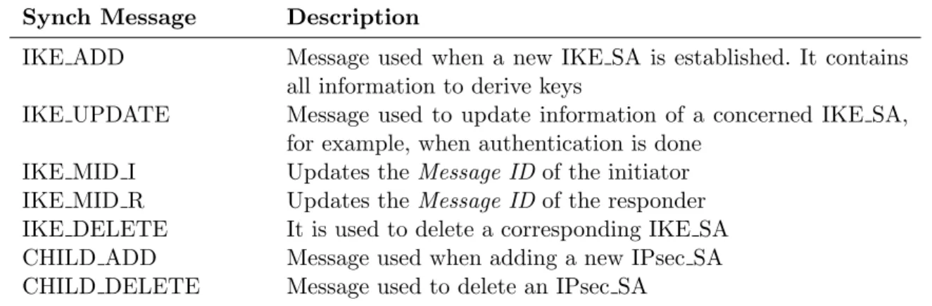
4.2 Synchronization messages of the HA plugin . . . 59
4.3 Control messages for segment changes notification . . . 59
5.1 Architectures and parameters addressed during tests . . . 76
5.2 Impact of the frequency of high availability events over QoS (considering the medians) . . . 89
5.3 Impact of the frequency of context management events over QoS (considering the medians) . . . 94
B.1 Solutions for each scenario . . . 122
B.2 Impacte de la fr´equence des ´ev`enements de HA sur la QoS . . . 127
B.3 Impacte de la frequence des ´ev`enements de Context Management sur le QoS . . . 128
Introduction
T
he Internet Service Providers (ISPs) are facing big challenges in order to manage the amount of mobile data traffic. During 2012, the global mobile traffic represented 70% more than 2011. Actually a 4G connection generated, in average, 19 times more traffic than a non-4G session. Moreover, in 2013 the number of mobile-connected devices will exceed the number of human beings, making the aggregate smartphone traffic in 2017 be 19 times greater than it is today [1]. Radio Access Networks (RAN) will not be able to face the exponential growth of such traffic. Thus, in order to avoid overloaded networks, operators would have to offload RAN traffic towards WLANs. While offloading, ISPs must provide the same Quality of Service (QoS) and equivalent trust level. Actually, RAN networks are considered trusted domains whereas WLANs networks are considered untrusted networks. However, one solution that provides a similar trust level over WLANs networks are the VPNs (Virtual Private Networks).One of the protocols that aims to protect IP traffic is IPsec, which is largely deployed as IPsec-based VPNs. These VPNs are designed to extend a trusted domain over an untrusted network. A VPN requires an End-User (EU) and the access network to agree on some security parameters in order to secure their IP traffic. This is done by establishing security associations (SA) between a Security Gateway (SG) and the EU. This may result in a large cluster of SGs managed by the ISPs at the same time.
The objective of this thesis is to allow IPsec VPN infrastructures to provide high QoS to EUs as well as to ensure continuity of service. More specifically, we want the VPN connections to be resilient to failures. This is what we call High Availability (HA) throughout this thesis. We also want that ISPs can easily manage the load due to the VPN traffic of their clients (this is what we call Traffic Management or Context Management ). As such, when a multinode VPN platform is being used by the ISP, it is able to transfer a VPN connection from one SG to another, introducing the concept of context transfer. Thus, when a VPN session is transferred, this means
2 1.1. Architectures of Interest
that all the parameters concerning that session are transferred as well. In fact, there are some scenarios where the possibility to transfer a VPN session from one SG to another has beneficial effects. Some use cases involve load-balancing of VPN traffic among different SGs, handover between different access networks or improvements of fail-over clusters with High Availability (HA) features.
Throughout this chapter, we present some architectures of interest and use cases in section 1.1. Then, we describe the VPN Service and introduce some technical challenges concerning the transfer of the security contexts. We also introduce two main architectures called Mono-LAN and Multi-LAN in section 1.2. Following section 1.3, presents the theoretical positioning of Context Transfer face to Mobility operation. Section 1.4 positions our investigations compared to some related works. Later on in section 1.5, we summarize our contributions to the community during this thesis, and finally, section 1.6 describes the organization of the manuscript.
1.1
Architectures of Interest
The goal of this section is to introduce some architectures of interest and scenarios where the IKEv2/IPsec context transfer may be used in real topologies. First, we explain the advantages of transferring the IKEv2/IPsec parameters and how we can use it to build a cluster of IPsec-based VPN service. Then, we present how the context transfer may improve EUs experience in offload scenarios.
1.1.1 Clustering IPsec Security Gateways
This architecture aims to create a cluster of IPsec Security Gateways. IPsec [2] is a layer 3 protocol aiming to protect IP communications. An End-User (EU) accessing the network must establish a VPN connection with a SG in order to gain access to some services. The goal of the cluster is to render the IPsec services highly available. The traffic between the EU and the cluster is protected with IPsec and the session is authenticated using Internet Key Exchange protocol (IKEv2). Our goal is to create a cluster of SGs aiming to improve the EU experience while protecting the communication with IKEv2/IPsec suite.
Figure 1.1 represents a cluster of SGs. It shows an EU establishing a VPN session with the cluster. For some reason (e.g. an overloaded SG, a failure on the responsible SG, latency, etc.), the SG must transfer its session to another SG within the cluster in order to ensure continuity of the VPN service. By doing so, the EU’s experience is improved because this represents less interruption of the communication, as the EU does not need to proceed a time consuming operation to re-establish a new VPN session from scratch. However, the session transfer requires
SG SG SG SG SG EU VPN CLUSTER SG SG APPLICATION’S TRAFFIC
IPSEC PROTECTED PATH
SG: SECURITY GATEWAY
EU: END-USER
IPSEC-CXT: IKEV2/IPSEC CONTEXT TRANSFER
VPN CLUSTER’S IP ADDRESS IPse
c-CX T
Figure 1.1: Clustering IPsec security gateways
also transferring the IKEv2/IPsec context from one Security Gateway to another. Two situations may come up; whether the SGs share the same IP address or have two different IP addresses. These situations are next referred to as Mono-LAN or Multi-LAN environments respectively (see section 1.2).
1.1.2 Offload Architectures
The mechanism called offload consists in switching the End-Users (EUs) from overloaded Radio Access Networks (RANs) towards some alternate wireless networks (e.g. WLAN like for example WiFi). These networks are more likely to be untrusted (when attaching other operator’s access points), unreliable and prone to not handle mobility operations. As a result, some operations like mobility, multihoming or security must be handled by the terminal itself (see [3]).
Once offloading towards the WLANs, operators need to maintain the same level of security as in RANs. For this reason, applying security at the radio layer only (L2) might not be sufficient since the WLAN access point is considered as untrusted when it does not belong to the same service provider. This leads the limitation of offloading only between the same operator’s access points. Another solution might be to secure at a higher layer, for example, at the transport layer or above (L4 or more). This means that applications have to be security-aware. Unfortunately,
4 1.1. Architectures of Interest
the applications in the market are reluctant to modify their source code for applying some sort of security (e.g. TLS or DTLS), as the EUs experience might decrease due to additional overhead, bandwidth consumption, additional certificate popups and additional computation. Furthermore, operators might favor to secure their communication with EUs at the IP layer (L3), as IPsec, to secure IP communications. IPsec not only secures at the IP layer but also secure the layers above.
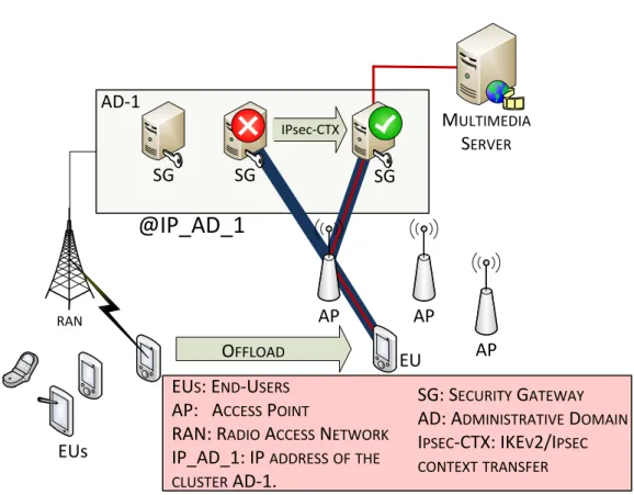
Figures 1.2 and 1.3 show two cases of interest representing some EUs being offloaded from RAN to WLAN. The first use case illustrates an EU attaching a cluster within a same administrative domain, whereas the second use case illustrates an EU moving between two VPN clusters placed in different administrative domains.
IKEv2/IPsec Context Transfer within the Same Administrative Domain
Figure 1.2 represents the first use case. An EU is offloaded from its RAN to a WLAN (WiFi). The peer needs to gain access to the multimedia server placed behind the cluster. Once the EU attaches the WLAN Access Point (AP), it obtains its IP address, which is used to establish a VPN tunnel towards the cluster. At this point, the EU gains access to the multimedia server in a secure manner. Since secure attachment is provided at the IP layer with the VPN cluster located in the ISP CORE network, the communication remains trusted even though WLAN APs may be untrusted.
There are some advantages whenever the operator may decide to transfer the VPN session from one SG to another SG within the cluster by implementing IKEv2/IPsec context transfer. For example, a VPN service provider may want to offer High Availability capabilities, support self-organization of the cluster, avoid overload SGs, improve bandwidth, reduce latency, among other features. However, if this context transfer happens between the same administrative domain where the SGs are configured with a single IP address (IP AD 1 in fig. 1.2), the EU is concerned by any signaling operations. Context transfer is transparent for EUs, as the IP addresses of both extremities of the VPN tunnel remain the same.
IKEv2/IPsec Context Transfer between Different Administrative Domains In contrast with the precedent use case, figure 1.3 represents the context transfer of the IKEv2/IPsec context between VPN clusters within different administrative domains. When this happens, the IP address of the VPN tunnel changes (from IP AD 1 to IP AD 2). Throughout this thesis, we call this kind of scenario Multi-LAN environments (see following section 1.2.1). This situation has an impact over the EU, because some IKEv2 signaling must take place in order to update the VPN session associated to the new IP address. The advantage of the context transfer between different administrative domains is that the EU avoids re-authenticating when moving from AD 1 to AD 2. Additionally, the EU continues to benefit from the features of a VPN cluster (e.g. load balancing, high availability, load sharing, etc.).
RAN
EUs
EUS: END-USERS
AP: ACCESS POINT
RAN: RADIO ACCESS NETWORK
IP_AD_1: IP ADDRESSOFTHE
CLUSTER AD-1.
OFFLOAD EU
SG SG
SG: SECURITY GATEWAY
AD: ADMINISTRATIVE DOMAIN
IPSEC-CTX: IKEV2/IPSEC
CONTEXTTRANSFER IPsec-CTX MULTIMEDIA SERVER SG AP
@IP_AD_1
AD-1 AP AP6 1.1. Architectures of Interest
RAN
EUs
EUS: END-USERS AP: ACCESS POINT
RAN : RADIO ACCESS NETWORK
IP_AD_1: IP ADDRESSOFTHECLUSTER AD-1. IP_AD_2: IP ADDRESSOFTHECLUSTER AD-2
OFFLOAD
EU SG
SG: SECURITY GATEWAY AD: ADMINISTRATIVE DOMAIN IPSEC-CTX: IKEV2/IPSECCONTEXT TRANSFER IPsec-CTX
@IP_AD_1
AD-1 AP AP SG AD-2 SG SG SG AP@IP_AD_2
MULTIMEDIA SERVER SG AP1.2
VPN Service description and technical challenges
1.2.1 High Availability of IPsec-based VPNs
A VPN service that offers High Availability (HA) features will improve EU’s experience when a failure occurs during an active session of an IPsec-based VPN. Indeed, the technical challenges to offer High Availability capabilities involves detection of a SG that does not work anymore, and letting a new SG to take responsibility of a previously established VPN session.
When an EU establishes a VPN with a SG, some cryptographic material and keys are derived between them. When the SG fails, we do not want the EU to re-negotiate all these parameters with another stand-by SG which is supposed to take responsibility of the VPN connection. Thus, the cryptographic material and keys must be shared between the failing SG and the stand-by SG. These parameters are referred to as the IKEv2/IPsec context and are explained in section 2.2.
We will consider the following architectures:
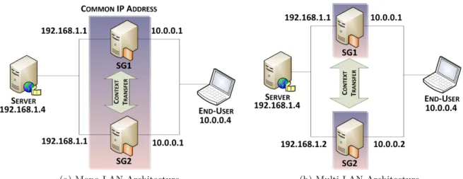
- Mono LAN: This architecture consists in a set of SGs that own the same IP address. As represented in figure 1.4a, both SGs share the same IP. However, unless some special mechanism is used, both SGs can not own the same IP address at the same time, due to duplicated IP conflicts (this is discussed in detail throughout the thesis). In this case, the EU does not need to update its IP attachment address when its connection moves from SG1 towards SG2, and the IKEv2/IPsec context is also transferred between both SGs.
- Multi LAN: The second architecture consists in a set of SGs that own different IP addresses. Figure 1.4b represents a Multi-LAN architecture, where SG1 and SG2 have different IP addresses. In this case, when a context transfer takes place, the EU is impacted because it must update its VPN’s destination IP address (i.e. one of the extremities of the tunnel). The EU can face this issue by performing specific IKEv2 exchanges like MOBIKE or REDIRECT extensions (see sections 2.6 and 2.7).
The biggest challenge to overcome a failure and to offer HA features concerns the synchronization of counters of the IKEv2/IPsec context. These counters control every incoming/outgoing IP packet protected with IPsec, preventing replay or unauthorized re-injection of previously processed IPsec traffic. These counters are referred together as IKEv2/IPsec counters. They must stay synchronized on both extremities when transferring a VPN session between different SGs. Ensuring their synchronization is a challenge that is addressed throughout this thesis.
8 1.2. VPN Service description and technical challenges
(a) Mono-LAN Architecture (b) Multi-LAN Architecture
Figure 1.4: IKEv2/IPsec context transfer scenarios
1.2.2 Traffic Management of IPsec-based VPNs
Transferring a VPN connection from one SG to another allows an EU to change its point of attachment towards the access network. The main challenge of transferring the VPN traffic concerning an IPsec connection is to enable a SG to transfer all the cryptographic material and derived keys from one SG to another. Traffic management might be confusing with HA feature. However, they differ in the fact that traffic management does not involve failure detection of a SG, while the HA features do detect this situation. As such, traffic management can be triggered whenever it is desirable, whereas HA capabilities are automatically launched once a SG fails.
As represented in figure 1.4a, the Mono-LAN architecture illustrates the case where both SGs have the same IP address. During a transfer of an IKEv2/IPsec context in Mono-LAN might have no impact to EUs. The point of attachment remains virtually the same, even though it is a new SG with the same IP address which ensures the communication. On the other hand, as represented in figure 1.4b, the Multi-LAN architecture illustrates the case where two SGs have different IP addresses. Thus, the EU is impacted because his point of attachment has changed too. These modifications can be done using MOBIKE or REDIRECT extensions. Note that the Multi-LAN scenario needs transferring IKEv2/IPsec context, which is not feasible with current standards.
Finally, table 1.1 summarizes the solution that addresses each scenario. For example, when performing traffic management under a Mono-LAN architecture, we need to perform Context Transfer in order to maintain the VPN session.
Mono-LAN Multi-LAN
High Availability HA ClusterIP Context Transfer + IP Mobility + HA Module Traffic Management Context Transfer Context Transfer + IP Mobility
Table 1.1: Solutions for each scenario
1.3
Context Transfer is not designed for Mobility
For clarity, this section shows how IKEv2/IPsec context transfer differs from protocols designed for mobility operations. The confusion between IKEv2/IPsec context transfer and mobility comes from the fact that a context transfer makes possible that a given IPsec session between an EU and a Security Gateway can be “moved” to another Security Gateway; whereas a mobility operation occurs when the EU changes its IP address. On the other hand, mobility use cases for Mobile IP (MIP) or MOBIKE (mobility extension for IKEv2), consider an EU attached to a Home Agent or a Security Gateway respectively. IP datagrams are tunneled to the EU. As a result of mobility, the outer IP address of the EU changes and needs to be updated in the Security Gateway or the Home Agent.
There are two available mechanisms to handle mobility and redirection of an IKEv2/IPsec context:
MOBIKE [3] is a mobility and multihoming extension for IKEv2. MOBIKE considers the following scenarios when an EU is connected to a SG using tunnel mode: first, if one of the peer changes its IP address, it can advertise the other node that its IP address has changed. This means that the outer IP address of the tunnel is updated. Note that with MOBIKE, a peer can advertise that its IP address has changed as well as it can be aware of mobility from the other extremity of the tunnel. The second scenario is multihoming. One of the peers can advertise the other peer of some alternate IP addresses where it is reachable if ever needed. These alternate IP addresses should be used in case the running IP address is not reachable anymore.
REDIRECT [4] is also an extension for IKEv2. It has been designed to redirect an IKEv2/IPsec session from one Security Gateway to another Security Gateway. The SG sends a REDIRECT message to the EU, indicating the new SG to attach. When the EU receives this message, it breaks the IKEv2/IPsec Security Associations established with the currently active SG and re-establishes/renegotiates all Security Associations with the new SG. Note that the EU is forced to renegotiate all the security parameters from scratch when being redirected to another SG. This may impact EU experience due to network delays while establishing a new VPN towards another SG. REDIRECT may happen when establishing of a VPN tunnel or during an active VPN session. On the
10 1.4. Related work and position of our work
other hand, REDIRECT mechanism does not consider the transfer of an IKEv2/IPsec context, which could actually ensure better continuity of service and improve EU’s QoS.
Now let us point out the differences between the context transfer and mobility operations:
1. With Mobility, the communication is established between two entities, the EU and the SG (or the Home Agent). These two entities remain the same before and after mobility occurs. Only the IP address of the EU is changed. On the other hand, with IKEv2/IPsec context transfer, the two entities before the context transfer and after the context transfer are different. In our case the SG is a different piece of hardware (device).
2. Mobility is only focused on the IP address, whereas IKEv2/IPsec context transfer carries all necessary security parameters of the IPsec session. This results from the fact that with mobility the entities remain the same, so both peers are aware of the session parameters.
In this section we mainly pointed out the differences between IKEv2/IPsec context transfer and mobility, as different protocols addressing different issues. This also means that these cases can be used together in a complementary manner. For example, when the IKEv2/IPsec context transfer takes place between two SGs that own different IP addresses (this is what we call a Multi-LAN architecture), then we can use mobility operations together with context transfer. Both mechanisms can be used as complementary solution, allowing to update the outer IP address of the tunnel as well as maintaining the IKEv2 and IPsec information previously negotiated. In summary, performing mobility and context transfer ensures a fluid continuity of service for a mobile node that changes it attachment IP address between different SGs.
1.4
Related work and position of our work
A few publications and works have already been published on IKEv2/IPsec context transfer, and to our knowledge, most of them considered a Mobile IP environment. In fact, when using Mobile IP, IPsec may be used to protect the tunnel between the Mobile Routers and the Home Agents and to protect the signaling between some access router and the EU.
1.4.1 Position towards theoretical proposed architectures
Georgiades et al. exposed a theoretical case of study in [5], where IPsec context transfer optimizes the transfer of some security context from a given device to another without renegotiating from scratch all the IPsec parameters. Georgiades et al. also introduced the concepts of homogeneous and heterogeneous security context transfer. This is actually the same analysis we arise when
describing a context transfer between the same administrative domains or between different administrative domains. Some authentication protocols (e.g. RADIUS, Diameter) are discussed throughout the article in order to determine the potential parameters during a security context transfer, but no details concerning the IPsec context are given. However, this study does not include any performance test or real implementation nor any simulation.
Similarly, [6] describes also a theoretical study proposition for an aeronautical use case, where an IKEv2/IPsec context is transferred between a Mobile Router and the Home Agent by using Context Transfer Protocol (CXTP [7]). They show that using IKEv2/IPsec context transfer saves almost 10 times the overhead produced by IKEv2/IPsec tunnel establishment. It presents the theoretical case where a Mobile Router switches its IPsec SAs from one Home Agent to another Home Agent, and presented IKEv2/IPsec context transfer as one way to optimize this inter Home Agent migration. The context transfer can be either triggered by the Mobile Router or by the Home Agent. Finally, a MOBIKE exchange is performed in order to update the IPsec database on both the MR and the new Home Agent, so the communication within the tunnel is maintained. However, the overhead calculation made in [6] does not take into account the additional delays during the CTD (context transfer data) exchanges between the old Home Agent and the new Home Agent. On the other hand, [6] does not give details of IKEv2/IPsec context parameters. Nevertheless, they explain the IKEv2 exchanges needed to establish an IKEv2/IPsec session. No implementation or performance test is conducted neither, although is considered as future work. In contrast, our investigation counts with several testbeds and performance tests.
[6] and [5] both introduce different theoretical frameworks for IPsec context transfer in mobility environments (Mobile IP - MIP). In fact, they use MIP for session mobility and MOBIKE extension for IPsec mobility. The Multi-LAN architecture addresses similar mobility use cases. However, we do not use MIP for the terminal mobility. Instead, we only based our mobility operations by using the MOBIKE extension of IKEv2. We believe that using a single protocol (e.g IKEv2) for session mobility, reduces the complexity of the architecture, managed by operational teams and thus favors its deployment. Furthermore, our work is not motivated by mobility but by High Availability and management of SG clusters. Mobility concerns one session whereas High Availability concerns all IPsec sessions of a given SG. This clearly rises scalability issues when all the IPsec contexts have to be transferred from one SG to the other. To address this issue, we define different manners to synchronize different IPsec databases of different SG and we define different strategies for transferring these contexts. In addition, we do not only define the architectures but we also implement and test the transfer of the IPsec context (see chapter 4).
Allard et al. [8] and Ayaz et al. [6] addressed the problem of uniqueness of the Security Parameter Index (SPI) of IPsec Security Associations. The SPI is used to uniquely identify the
12 1.4. Related work and position of our work
corresponding security association of a tunnel. However, a collision of SPIs could happen when transferring IKEv2/IPsec contexts between different devices. Allard et al. psopose MOBIKE in order to avoid SPI collisions. In contrast, [6] uses HELLO messages (see [9]) to prevent SPI collisions before the context transfer takes place. In order to address this issue in Multi-LAN environments, we use the solution described in [8], as we base our mobility operation solution by using MOBIKE. Allard et al. in [8] identified all the parameters for both IKEv1/IPsec and IKEv2/IPsec contexts. However, the transfer of context was implemented for MIP architectures and not High Availability ones, which involve different constraints as presented in section 1.3. Following section 1.4.2 positions our work from an implementation point of view with [8].
1.4.2 Position towards existing implementation
Allard et al. in [8, 10–14] are the only pieces of work that mention the existence of an implementation concerning IPsec context transfer. Allard et al. not only proposed the CXTP protocol to transfer an IKE/IPsec context as in [6], but they also considered other use cases as the Protocol for Carrying Authentication for Network Access (PANA) and Mobile IP (MIP). In [8], chapters 9, 11, 12 and 13 are dedicated to present the PANA context transfer simulation based on a software called OMNet++.
Considering the similarity of our investigation with the work done by Fabien Allard, in the remaining of this section we next position our work against his thesis [8]:
Throughout this thesis, we concentrated on the usage of the version 2 of the Internet Key Exchange (IKE) protocol as the mechanism to perform authentication between a node and a SG. All of the architectures in [5,6,8,10–14], are using MOBIKE to update the IPsec databases after the context tranfer occurs. MOBIKE is an extension of IKEv2 and there are no equivalence for IKEv1. Even though IPsec context transfer for IKEv1 has been implemented by Fabien Allard, the proposed architectures had never been evaluated with a real implementation. In order to evaluate this architecture, a new implementation based on IKEv2 is needed. In addition, IKEv2 proposes multiple extensions that our architectures are using: management of IKEv2/IPsec sessions (i.e. REDIRECT), mobility and multihoming operations (i.e. MOBIKE) and High Availability protocols [15].
Allard et al. implemented the IKEv1/IPsec context transfer on racoon implementation. Racoon is actually deprecated and there is no upgrade to IKEv2. We choose to implement the context transfer on strongswan [16], the reference open source implementation for IKEv1 and IKEv2, and we could hardly reuse the code developed for racoon implementation. In addition, Allard et al. in [8, 11] use an implementation called PF KEY to manipulate the IPsec related kernel information. PF KEY originates from BSD, and is implemented in Linux as well. However, it is now deprecated and was replaced by an implementation called XFRM,
which is newer and more robust. We based our implementation on XFRM, which actually allows updating sequence number values of IPsec Security Associations. We managed to separate each parameter of the security association within the implementation in order to update these counters (for IKE and IPsec), whereas such achievement ins not possible with PF KEY.
Allard et al. tested their implementation using an UDP traffic generator. This traffic generator has been configured to reproduce UDP packets every 50ms within a single VPN established session. We consider this experimentation is a proof of concept, however, as mentioned by Allard et al., under heavy traffic situations, more work is needed to handle IKEv2/IPsec counter synchronization. In our case, we tested our implementation under heavy load situations, which give us a clear response of the impact against upper layers. Additionally, we tested how IKEv2/IPsec context transfer impacts real time services through network measurements as well as Quality of Services (using POLQA [17]) for audio streaming services. In contrast with UDP traffic generator, we tested our architecture with different transport layers like TCP/HLS, UDP/RTSP; measuring the impact at the application layer. Using QoS, we prove that our solution has no major impact on End-User’s services.
1.4.3 Detailed position towards High Availability vs. Mobility scenarios
In an architectural point of view, our work differs from previous work in the use cases we address. The scenarios that motivated our work are not mobility but High Availability and Cluster management. In a Mobile IP (MIP) environment, a Mobile Router (MR) is transferred from one Home Agent to another Home Agent, and the IKEv2/IPsec context is transferred between Home Agents with the purpose to optimize the handover and reduce latency. On the other hand, our work considers two different scenarios, and both involve clusters of Security Gateways.
The first scenario considers a cluster of Security Gateways. All of them are seen by the EU as a single IP address. Motivation for moving a session from one SG to the other is to manage the cluster and to provide High Availability features. The difference with Mobile IP environments, is that no interaction is required between the EU and the Security Gateway during the IKEv2/IPsec context transfer (the transfer is transparent to EUs). Also, by providing High Availability, each SG within the cluster is associated to a standby node that takes in charge the traffic in case of failover. In summary, the main differences compared to mobility operations are explained as follows:
1. First, failovers cannot be prepared in advance like in mobility operations. Second, all communications are transferred in a High Availability scenario, instead of one single tunnel during mobility. These two constraints impose to synchronize IPsec databases between the active node and the standby node within the cluster. This shared database requires to be
14 1.5. Contributions
updated for every IKEv2 or IPsec packet, since any inbound or outbound packet updates IPsec or IKE counters. With heavy load this is hardly possible, as a result we define different strategies according to the load the Security Gateways have to deal with. 2. We define a synchronization timer for IKEv2 and IPsec databases. This timer can be
dynamically assigned according to the load,the more loaded the active node is, the longer the timer should be. Once the duration of the timer has been defined, the IPsec and IKEv2 databases are synchronized periodically based on the timer policy. During a failover event, the IPsec standard allows to increase the IPsec database counters in order to resynchronize stale values once a context transfer is performed. In contrast, if the timer cannot be increased (e.g. heavily loaded SGs scenarios), then the active node must perform additional IKE exchanges in order to resynchronize IKE SA’s counters (see chapter 4). The reason why IKE SAs synchronization gets higher priority compared to IPsec SAs, is that an IPsec SA can be re-synchronized using different mechanisms like REKEY, creation of a new IKE SA or eventually resynchronization using the IKEv2 channel. However, if desynchronization occurs with the IKEv2 counters, then synchronization through IKE exchanges is the only mechanism that makes possible IKEv2 counter resynchronization. Currently we are not aware of any implementation of this protocol (see [15]).
3. When loads keep on increasing, then counters cannot be synchronized anymore. To avoid a re-negotiation of the IKEv2 channel, the EU must implement the synchronization protocol.
The second scenario we considered is a transfer between clusters that have different IP addresses. In this case, interaction between the EU and the clusters is necessary. However, transfer from one cluster to the other is only performed using IKEv2 signaling. In other words, we are not using Mobile IP signaling to perform mobility.
Finally, we present a solution to offer IPsec High Availability features. For this reason, we focus on a mechanism named ClusterIP, consisting in creating IP-based clusters with no dedicated hardware. ClusterIP allows to implement High Availability features and ensure connectivity during failovers of the SGs. The goal of ClusterIP is to share a common IP address with the purpose to build a cluster of machines in order to spread the load of incoming/outgoing IP packets. ClusterIP is based on firewalling rules under Linux environments. However, in order to implement ClusterIP under IKEv2/IPsec environments, we had to use the XFRM implementation that allows to get and set the IPsec sequence numbers.
1.5
Contributions
Our first contribution concentrates on identifying the elements composing an IKEv2/IPsec context (i.e. all the cryptographic material, derived keys and other parameters that are
negotiated during the establishment of a VPN tunnel).
A second contribution, implements two new functions called GET and PUT, aiming to extract and inject an IKEv2/IPsec context on a real IPsec stack. This work is done based on the VPN open source solution called strongSwan (v4.5.0) and Linux (Ubuntu 11.04). Our developments are published as open source projects and can be used by the research community. Additionally, we establish an experimental platform, and we perform intensive performance tests. For instance, we conduct some tests with heavily loaded SGs (several VPN tunnels at the same time), demonstrating how smooth can be an IKEv2/IPsec context transfer, and how interesting is this approach for real deployment by operators.
Our third contribution is related to the Mono-LAN environment and gives an extensive performance comparison between an existing ClusterIP solution and our context transfer approach. Once again, we performed some performance tests with real trafic (e.g. streaming with TCP or UDP), demonstrating the feasability of the proposed solution.
We also approached the IKEv2/IPsec context transfer implementation under Multi-LAN environments. We present a theoretical framework to perform context transfer between SGs with different IP addresses.
Throughout this thesis, we faced some difficulties for addressing an appropriate solution. The first obstacle concerned the complexity and understanding of IPsec together with IKEv2. Both protocols are defined in different standards and involve a massive list of parameters that are negotiated in order to establish a VPN tunnel. However, as in any research project, this is part of an exhaustive study. Then, further investigations lead us to face some development challenges. Getting inside the source code of strongSwan is a complex task. Understanding the features of this VPN solution represented one of the main difficulties throughout this thesis. The following difficulties concerned mainly networking and security network issues. In addition, our validation tests are also consider as a proof of concept. However, we insisted in running performance tests and measuring the impact on EU’s experience for each scenario studied.
These investigations were published as scientific papers at different conferences: The International Conference on Secure Networking and Applications [18] (ICSNA 2013), The Third International Conference on Communications and Information Technology [19] (ICCIT 2013), the 8th International Conference on Availability, Reliability and Security [20] (ARES2013) and Proceedings of IEEE Global Telecommunications Conference - Communication and Information System Security [21] (GLOBECOM ’12) .
16 1.6. Thesis Organization
1.6
Thesis Organization
The remainder of the manuscript is composed of six chapters. Chapter 2 introduces all the basic knowledge needed for a good understanding of the document. The description includes IKEv2/IPsec protocols, and also introduces REDIRECT, MOBIKE and ClusterIP mechanisms. Chapter 3 identifies the elements to be included in the IKEv2/IPsec context. We present our initial results of GET and PUT functions, by illustrating the time it takes to recover an IKEv2/IPsec session as well as the time for reinstalling the context again in the same gateway. Chapter 4 and 5 are dedicated to the Mono-LAN architecture. First, we analyze how ClusterIP (introduced in 1.3 and described in 2.5) improves the availability of a VPN service and then we show some results of our test-bed. In addition, we observe the drawbacks and benefits of this solution. Then, we define two architectures for IKEv2/IPsec environments: High Availability and Traffic Management. We present our implementations through GET and PUT functions, which are the heart of the IKEv2/IPsec context transfer.
In chapter 6, we address VPN platforms under Multi-LAN environments. We present a theoretical solution allowing to perform context transfer between different SGs owning different IP addresses. We show how the EU is impacted by the alteration of the IP address and how to solve this issue as well as other factors.
Finally, chapter 7 includes the conclusions of our investigations and the future work, as well as a description of the global evolution of the network concerning IPsec.
Security for IP Networks
Roadmap of IPsec and IKEv2
protocols
T
his chapter provides an overview of the services, protocols and mechanisms that are involved in providing security based on IPsec and IKEv2. It also defines some mechanisms that provide mobility and flexibility for IPsec/IKEv2, as well as some methods that allow management and clustering at the IP layer. The goal of this theorical state of the art is to position most of the mechanisms that were used during practical tests and are often mentioned through next chapters.2.1
Security Services
This section introduces some security services (also defined in [22]). Different protocols (e.g. TLS, IPsec, Https) might offer these services at different layers of the OSI model.
Data integrity: the property that data have not been altered or destroyed in an unauthorized manner. In other words, during an IPsec-based communication, data integrity allows verifying that the contents of an IP datagram were not changed, either deliberately or due to random errors.
Data origin authentication: the corroboration that the source of data received is as claimed. It allows a node to verify that each incoming IP datagram was originated by the claimed sender (source of data).
Peer entity authentication: the corroboration that a peer entity in an association is the one claimed. This service involves the identification and authentication of the peer. Identification refers to an entity (user, equipment) claiming its identity by providing an identifier (usually a name, pseudonym, IP address, domain name). Authentication consists
20 2.2. IPsec: Security Associations and Databases
in providing the claimed identity by providing one or several authentication elements, known as credentials.
Data confidentiality: the property that information is not made available or disclosed to unauthorized individuals, entities or processes. As such, confidentiality transforms data from an intelligible format (plaintext) to an unintelligible format (ciphertext). It ensures that an unauthorized attacker or eavesdropper could not understand what is being transmitted during IPsec-based communications, this reverse action is known as decryption.
Replay detection: consists for an entity to detect that received data are duplicated from a previous exchange. Some data might have been sent in a secure manner by a legitimate entity; but they can be copied and injected again to the same destination. Data are still authentic but they are already processed several times.
Access control: the prevention of unauthorized use of a resource, including the prevention of use of a resource in an unauthorized manner. For IPsec, access control concerns a host or a Security Gateway. Only authorized hosts or Security Gateways that are intended to establish IPsec communications will be allowed to do so.
2.2
IPsec: Security Associations and Databases
IPsec is a protocol that proposes to secure any IP based communication by providing security services (see 2.1). It is defined in [2]. IPsec offers interoperable, high quality and cryptographically-based security for both Internet Protocol versions: IPv4 and IPv6. The most common usage of IPsec consists in creating tunnels, often called Virtual Private Networks (VPNs). Actually, IPsec is used to create trusted environments through unprotected networks. When an entire network is being protected with IPsec, then tunnel mode is used. Otherwise, when the communication exclusively takes place between two hosts, then transport mode is more suitable. Figure 2.2 illustrates the scenarios where tunnel mode can be used, while figure 2.1 illustrates the transport mode scenario.
A Security Association (SA) is a data structure that contains security parameters to allow instantiation of an IPsec communication. The set of SAs is stored in the Security Association Database (SAD). Its goal is to offer security services for incoming/outgoing traffic it carries. As a SA is unidirectional, two SAs are needed in order to protect both ways of a bidirectional IPsec-based communication. In addition, some data are also stored in the Security Policy Database (SPD). The SPD is consulted to define appropriate behavior facing incoming and outgoing IP packets by specifying which traffic should be protected with IPsec or should bypass IPsec. It is consulted for all inbound and outbound traffic. The SA relies on Authentication
Internet
IPsec Transport Mode
IPsec protected path
Host A Host B
Figure 2.1: IPsec transport mode scenarios.
Internet
IPsec Tunnel Mode
IPsec protected path
Host A Host B
(a) Endpoint to Endpoint Tunnel
Internet
IPsec Tunnel Mode
IPsec protected path Host A
Host B Protected Subnet
IPsec Security Gateway
Extremity of the tunnel Extremity of the tunnel
(b) Endpoint to Gateway Tunnel
Internet
IPsec Tunnel Mode
IPsec protected path Host A Protected Subnet IPsec Security Gateway Host B Protected Subnet IPsec Security Gateway
Extremity of the tunnel Extremity of the tunnel
(c) Gateway to Gateway Tunnel Figure 2.2: IPsec tunnel mode scenarios.
Header (AH; see section 2.3.1) and Encapsulating Security Payload (ESP; see section 2.3.2) protocols to offer its security services. Finally, all the parameters concerning SAD and SPD could be configured manually by an administrator or could also be configured dynamically thanks to the Internet Key Exchange Protocol (IKE). When IKE is used (which is mostly the case), an additional database known as Peer Authorization Database (PAD) links each authorized identity to its corresponding security parameters, thus, providing a link between IKE and each policy stored in the SPD. Further details concerning IKE are explained in 2.4.
IPsec can be deployed under different scenarios. Depending on the concerned topology, IPsec can be configured in two modes: transport mode or tunnel mode. Even if both modes use the same techniques and algorithms to encrypt/decrypt, the difference relies on the encapsulation and how a packet is built. Each mode has its own uses and thus it is important to care about the selected one in order to run IPsec properly.
22 2.3. IPsec Protocols ORIGINAL IP HEADER PAYLOAD NEW IP HEADER AH HEADER PAYLOAD ORIGINAL IP HEADER HASH UNPROTECTED PROTECTED INTEGRITYPROTECTED
(a) Authentication Header in Tunnel Mode
ORIGINAL IP HEADER
P
AYLOAD ORIGINAL IP HEADER AH HEADERP
AYLOAD HASH UNPROTECTED PROTECTED INTEGRITYPROTECTED(b) Authentication Header in Transport Mode Figure 2.3: IPsec Encapsulation Protocol: Athentication Header
2.3
IPsec Protocols
2.3.1 Authentication Header
The Authentication Header (AH) is defined in [23]. It offers integrity, data origin authentication and an optional anti-replay protection. The AH header (as in fig 2.3), serves to transport the result of the integrity check over the entire original packet. As no encryption is performed, Authentication Header does not ensure confidentiality and consequently has a much simpler header than ESP. The AH header format depends on whether tunnel or transport mode is used. Figure 2.3 shows in detail how the AH header is built when the original IP packet is being protected using Authentication Header protocol in both transport and tunnel modes.
2.3.2 Encapsulation Security Payload
The Encapsulating Security Payload (ESP) protocol is defined in [24]. Depending on the configuration parameters, ESP can offer confidentiality, data origin authentication, data integrity and anti-replay services. The ESP header is more complex than the AH header. Figure 2.4 shows in detail how the ESP fields are built using both transport and tunnel modes. Notice that ESP not only adds a header between the IP header and the payload of the packet, but it also adds some fields at the end of the packet. So the fact that ESP fields enclose the original payload, makes security more complex than with AH which only adds an header.
ORIGINAL IP HEADER PAYLOAD NEW IP HEADER PAYLOAD ORIGINAL IP HEADER UNPROTECTED PROTECTED ESP HEADER ESP TRAILER ESP AUTH HEADER INTEGRITY PROTECTED ENCRYPTION PROTECTED
(a) Encapsulation Security Payload in Tunnel Mode
ORIGINAL IP PAYLOAD ORIGINAL IP ESP HEADER PAYLOAD UNPROTECTED PROTECTED ESP TRAILER ESP AUTH HEADER INTEGRITY PROTECTED ENCRYPTION PROTECTED
(b) Encapsulation Security Payload in Transport Mode Figure 2.4: IPsec Encapsulation Protocol: Encapsulation Security Payload Header
2.4
Security Management: Manual Vs. IKEv2 protocol
Secrets are used as input keys for cryptographic algorithms. Naturally, the simplest idea concerning a shared secret would be to physically exchange it. Then, each peer can associate a host with its corresponding key. Unfortunately, this technique presents security risks when the exchange of secrecy is done under an uncontrolled environment. Additionaly, it is not scalable when deploying major infrastructures.
As mentioned in section 2.2, IPsec offers different security services by maintaining a shared state between the source and the destination of an IP datagram. This state defines the security services provided, as well as the cryptographic algorithms and their input keys. As cited above, maintaining this shared state in a manual fashion is not scalable at all. Hence, IKEv2 was designed to allow dynamic establishment and update of Security Associations, as well as the exchange of secret used as input to the cryptographic algorithms. IKE stands for Internet Key Exchange protocol. IKEv2 (defined in [25], [26]) is an improved version 2 of its predecessor IKEv1 (defined in [27], [28] and [29]). Throughout this thesis work, IKEv1 is not discussed at all because it is an obsolete version of the protocol. Henceforth, only IKEv2 is argued.
How does IKEv2 protocol work?
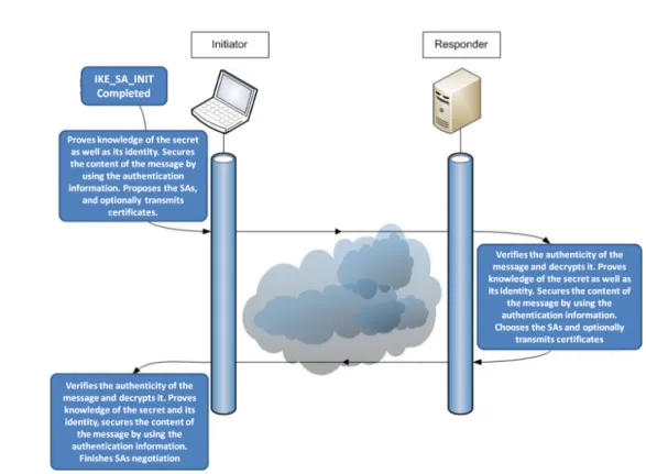
Every IKEv2 exchange consists in a pair of messages: a request and a response. A peer that sends the first request is called INITIATOR, while the other peer is called RESPONDER.
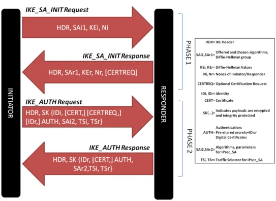
Initial exchanges of IKEv2 perform mutual authentication between the peers and establish an IKE Security Association (IKE SA). An IKE SA consists in a userland shared state used to negotiate further Security Associations for ESP and/or AH. Actually, these SAs for ESP and/or AH are referred as CHILD SA or IPsec SA. Figure 2.5 shows the IKEv2 exchanges in order to successfully establish an IPsec-based VPN.
24 2.4. Security Management: Manual Vs. IKEv2 protocol
Figure 2.5: IKEv2 message exchanges, IKE INIT and IKE AUTH
and performs a Diffie-Hellman exchange. The following exchange IKE AUTH transmits identities, demonstrates knowledge of the secret and negotiates the first CHILD SA (i.e. the Security Association parameters). Only after both IKE SA INIT and IKE AUTH have been acknowledged, further requests can be transmitted. The CREATE CHILD SA exchange allows to create a new CHILD SA. And the INFORMATIONAL exchange allows to perform IKEv2 management tasks, like IP mobility, deletion of IKE SAs, liveness verification, among others.
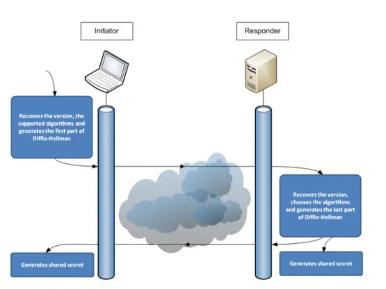
2.4.1 Exchange Description: IKE SA INIT
This exchange helps to establish trust settings which ensure future IKE exchanges. Figure2.6 shows an graphic explanation of the IKE SA INIT request and response.
The INITIATOR sends the following information:
SPI : security association unique identifier. Version Number: set to version 2 (e.g. IKEv2). SAi1 : cryptographic algorithms proposed. KEi1 : Diffie-Hellman values.
Figure 2.6: IKE SA INIT exchange details.
The responder replies with the following information: SPI : security association unique identifier. Version Number: set to version 2 (e.g. IKEv2).
SAr1 : cryptographic algorithms chosen (based on proposition SAi1 ). KEr1 : Diffie-Hellman exchange.
Nr: RESPONDER’s nonce.
CERTREQ: if present, this optional field asks for a certificate.
At this point, both parties can generate a SKEYSEED, a shared secret from which all keys are derived for that IKE SA. The first key, usually called SK e, is used for encryption. The second one, for integrity, is called SK a. And finally, the SK d, is the key used to derive the keys for the CHILD SAs (once again, keys for encryption and integrity protection).
2.4.2 Exchange Description: IKE AUTH
During the IKE AUTH exchange, both peers authenticate each other, and the first CHILD SA is negotiated. Figure 2.7 illustrates the IKE AUTH exchange.
26 2.4. Security Management: Manual Vs. IKEv2 protocol
Figure 2.7: Detailed IKE AUTH exchange.
The INITIATOR sends the request with the following information: SPI : security association unique identifier.
Version Number: set to version 2 (e.g. IKEv2). IDi: INITIATOR identity.
CERT: INITIATOR certificate(s) (i.e. public key). CERTREQ: optionally ask for a certificate.
IDr: optional RESPONDER identity to specify which of the responder’s identities it wishes to talk to (i.e. a host running multiple identities).
AUTH : a block of data protected with integrity protection (e.g. digital certificates or pre-shared keys + ID )
SAi2 : cryptographic algorithms proposed for the CHILD SA.
TSi: defines the source address of the traffic forwarded from the INITIATOR of the CHILD SA.
TSr: defines the destination address of the traffic forwarded to the RESPONDER of the CHILD SA.
The RESPONDER sends a response with the following information: SPI : security association unique identifier.
Version Number: set to version 2 (e.g. IKEv2).
IDr: confirms identity by sending the RESPONDER’s identity (IDr).
CERT: RESPONDER certificate with the public key to verify the AUTH field. AUTH : all information which is used to perform integrity protection.
SAr2 : cryptographic algorithms selected for the CHILD SA.
TSi: defines the source address of the traffic forwarded from the INITIATOR of the CHILD SA.
TSr: defines the destination address of the traffic forwarded to the RESPONDER of the CHILD SA.
2.4.3 Authentication of IKE SA
The authentication of the IKE SA could be achieved in three different manners: Pre-shared keys, X.509 Certificates or EAP (Extensible Authentication Protocol).
The easiest method to configure and authenticate IKE SAs is the pre-shared key, where both entities keep the same secret in a secure place. Security risks might be the main drawback of this authentication method due to the difficulty to keep the ”shared” secret in a safe place. Also, the shared secret must be distributed among the entities that comunicate, which also represent a risk.
The authentication through certificate X.509 is another way to authenticate endpoints but demands a more complex system. The X.509 certificates use an algorithm based on assymetric cryptography. This method uses two cryptographic keys per user: a public key and a private key. The certificate authority certifies that both keys are unique per user and are properly linked. Depending on how these keys are used, the user can ensure integrity protection of the message as well as the identity of the sender. The sender signs the data using its private key and sends it to other users. Thanks to this signature, all recipients can verify the integrity and identity of the message by using the public key of the sender.
However, there are scenarios where the pre-shared key method does not scale well or the distribution of certificates X.509 is too complicated for the administrator (E.g. too much users). Thus, EAP-IKEv2 protocol consists in other way to perform authentication. EAP-IKEv2 uses an additional exchange towards an authenticator EAP server to authenticate endpoints. Details of EAP with IKEv2 can be found in [30].
28 2.5. Clustering at the IP layer: ClusterIP
2.5
Clustering at the IP layer: ClusterIP
ClusterIP is an implementation based on recent Linux kernels (2.6 and higher). It permits load-balancing features without having a physical load-balancer. It is a smooth way to distribute the load of incoming IP packets in a very autonomous manner (each node can decide whether it is responsible or not for each incoming IP packet).
However, let us first introduce the notion of a cluster. In a computer system, a cluster is a group of servers and resources that act like a single system. These are commonly used to offer high availability, parallel processing or load balancing. Cluster members may exchange some data in order to be able to offer these features.
Under Linux kernel distributions, iptables is an implementation which configures, maintains, and inspects firewalling rules. It identifies an IP packet that matches a defined rule. This action is called target. ClusterIP is an extended target module of iptables, allowing to build a cluster of machines that share a common IP address without having a physical machine that performs this task. Indeed, ClusterIP is intended to provide load-balancing and clustering features without having a dedicated load-balancer machine. Thus, ClusterIP consists in a loadbalancer-less cluster on Linux operative system. It simply enables a server to calculate responsibility of incoming IP packets so that the server can decide by itself either it has to treat it or not.
When using a ClusterIP approach, no special hardware is required to benefit from its load-balancing and clustering features. The configured members of the cluster share a common multicast MAC address and thus receive the same packets. Then, a lower-layer mechanism (ClusterIP) filters packets at the IP layer by calculating responsibility through an algorithm (E.g. hashing the IP source of each packet). When used in command line interface, ClusterIP is a parameter of the iptables command.
The following parameters are set when implementing ClusterIP:
–new: creates a new cluster. Must be the first rule in the list of rules.
–hashmode mode: mode of hashing. Must be one of the following: sourceip, sourceip-sourceport, sourceip-sourceport-destport.
–clustermac mac: multicast MAC address of the cluster. –total-nodes num: total number of nodes within this cluster.
–local-node num: the id number of the local node within the cluster. –hash-init rnd: a random seed for hash initialization.