Science Arts & Métiers (SAM)
is an open access repository that collects the work of Arts et Métiers Institute of
Technology researchers and makes it freely available over the web where possible.
This is an author-deposited version published in: https://sam.ensam.eu Handle ID: .http://hdl.handle.net/10985/9674
To cite this version :
Stephania KOSSMAN, Didier CHICOT, Xavier DECOOPMAN, Alain IOST, Adrien VAN GORP, E. MEILLOT, Eli-Saul PUCHI-CABRERA, Y.Y. SANTANA, Mariana STAIA - Sliding Wear Response of Nanostructured YSZ Suspension Plasma-Sprayed Coating - Journal of Thermal Spray
Technology - Vol. 23, n°8, p.1350-1361 - 2014
Any correspondence concerning this service should be sent to the repository Administrator : archiveouverte@ensam.eu
Sliding Wear Response of Nanostructured
YSZ Suspension Plasma-Sprayed Coating
S. Kossman, D. Chicot, X. Decoopman, A. Iost, A. van Gorp, E. Meillot, E.S. Puchi-Cabrera, Y.Y. Santana, and M.H. Staia
Nanostructured yttria-stabilized zirconia coatings for applications in high-temperature environments can be deposited by suspension plasma spraying (SPS) techniques. The present research has been conducted in order to study the sliding wear response of a SPS ZrO2–8% mol. Y2O3coating (75lm in thickness) deposited onto a Haynes 230 substrate, using pin-on-disc tests. Some of the coated samples were sub-sequently heat-treated for 1 h at 300 and 600!C. Samples characterization prior and after the wear tests was carried out by SEM, EDS, XRD and optical profilometry techniques. Instrumented indentation was employed to determine elastic modulus and hardness. The results have shown that the as-sprayed and heat-treated samples experienced severe wear (10213m3/Nm) and the worst wear performance corre-sponded to the sample heat treated at 600!C. Such a behavior could be related to both the structural changes that took place during heat treatment and the nature and level of the residual stresses in the coatings. In general, the morphologies of the wear tracks observed by SEM have shown a smoothing of the surface, brittle fracture, smearing and grain pull-out.
Keywords heat treatment, nanoindentation, nanostructured coating, suspension plasma spray, wear, yttria-stabilized zirconia
1. Introduction
As industry develops, the need of new materials that can withstand more severe and critical conditions has become a major concern. Currently, there is a special interest in the manufacture of finely structured coatings (nanometric or sub-micrometric sized) for industrial applications. Many of the new developed technologies include these coatings in their designs due to their indus-trially recognized benefits on mechanical properties, as well as corrosion and wear resistance under high-temper-ature environments. Some of the most common applica-tions for these coatings are environmental barriers for
photocatalytic applications, electric insulation for solar energy generators, thermal insulation in industrial gas turbines and aero turbines, and ionic and electronic con-ductors for solid oxy-fuel cells, amongst others (Ref1,2). Many studies have revealed that decreasing the scale of the coating structure to the nanometer scale during ther-mal spray processing leads to a considerable improvement of mechanical properties and tribological behavior regarding friction coefficient and wear rate, in comparison with conventional coatings (Ref3–7).
Suspension plasma spraying (SPS) is a relatively new plasma spray process that has been used in the last 10 years, that allows the possibility of elaborating thinner coatings, which exhibit either nanometer or sub-micrometer sized architecture, in comparison with those resulting from the traditional processing. This method consists in mixing nanometric or sub-micrometric particles with a liquid carrier phase, usually distilled water or eth-anol and some dispersant to maintain the suspension sta-bility and avoid agglomeration. The suspension is injected
S. Kossman, School of Metallurgical Engineering and Materials Science, Faculty of Engineering, Universidad Central de Venezuela, 47885, Los Chaguaramos, Caracas 1041, Venezuela and Laboratoire de Me´canique de Lille, LML, UMR 8107, UST Lille, IUT A GMP, BP 90179, 59 653 Villeneuve d_Ascq, France; D. Chicot and X. Decoopman, Laboratoire de Me´canique de Lille, LML, UMR 8107, UST Lille, IUT A GMP, BP 90179, 59 653 Villeneuve d_Ascq, France; A. Lost and A. Van Grop, Arts et Me´tiers ParisTech, MSMP, 8, Boulevard Louis XIV, 59000 Lille Cedex, France; E. Meillot, CEA, DAM, Le Ripault, 37260 Monts, France; E.S. Puchi-Cabrera, School of Metallurgi-cal Engineering and Materials Science, Faculty of Engineering, Universidad Central de Venezuela, 47885, Los Chaguaramos, Caracas 1041, Venezuela and Laboratoire de Me´canique de Lille, LML, UMR 8107, UST Lille, IUT A GMP, BP 90179, 59
653 Villeneuve d_Ascq, France and Venezuelan National Academy for Engineering and Habitat, Palacio de las Academias, 1723, Caracas 1010, Venezuela; Y.Y. Santana, School of Metallurgical Engineering and Materials Science, Faculty of Engineering, Universidad Central de Venezuela, 47885, Los Chaguaramos, Caracas 1041, Venezuela; M.H. Staia, School of Metallurgical Engineering and Materials Science, Faculty of Engineering, Universidad Central de Venezuela, 47885, Los Chaguaramos, Caracas 1041, Venezuela, Arts et Me´tiers ParisTech, MSMP, 8, Boulevard Louis XIV, 59000 Lille Cedex, France and Venezuelan National Academy for Engineering and Habitat, Palacio de las Academias, 1723 Caracas 1010, Venezuela 1041, Venezuela. Contact e-mail: stephaniakossman@gmailcom.
into the plasma jet and can be deposited over low roughness substrates (Ref8–11).
SPS coatings exhibit a granular morphology consisting of two grain types. On the one hand, there is a mixture of melted and unmelted particles, which have the shape of the original feedstock particles and which travel in the colder regions of the plasma flow. On the other hand, there are small spherical grains, which correspond to re-melted particles before their impact upon the substrate. This morphology differs considerably from the typical anisotropic lamellar structure that characterizes the tra-ditional atmospheric plasma spraying (APS) coatings (Ref
8, 10, 12). Currently, yttria-stabilized zirconia (YSZ) coatings are widely used for thermal barrier coatings (TBCs) as well as solid oxide fuel cells (SOFCs) applica-tions, due to properties like high hardness, wear resis-tance, ion conductivity, thermal expansion coefficient similar to superalloys, etc., which in turn depend on the coating architecture, i.e. if it is porous or dense, respec-tively (Ref9,12–14).
Zirconia is a polymorphic ceramic material, which exists in three well-known structural forms: monoclinic, tetragonal and cubic. It is often doped with Y2O3 (yttria)
or other oxides to avoid its spontaneous transformation (Ref 15, 16). It has been shown that yttria partially sta-bilized zirconia (YPSZ) nanostructured coatings depos-ited by APS exhibit enhanced properties such as increased wear resistance, bond strength and microhardness, in comparison with the conventional coatings of the same composition (Ref5,8,17).
The tribological behavior of YSZ coatings is very sen-sitive to the microstructure, especially to porosity, micro-cracking and inclusions present in the as-sprayed (AS) condition. Also, chemical properties of ceramics have an important role in the wear behavior since their reactions with humidity can cause zirconia embrittlement (Ref 18,
19). Moreover, a strong dependence on temperature has been determined, changing from a low to a high wear regime with the increase of temperature and sliding speed. Earlier studies pointed out that the wear mechanisms of traditional plasma-sprayed zirconia coatings could be se-vere fracture, grain pull-out, smearing of the worn mate-rial, fatigue spalling, plastic deformation and material transfer, depending on the nature of the material and testing conditions (Ref17,20,21).
For most of the YSZ coatings applications, the control of phase composition is imperative for optimal lifetime. Larger amounts of the monoclinic phase are undesirable, since, on heating, this transforms into the tetragonal phase, accompanied by a large volume change, leading to premature failure. Coatings made of fully stabilized zir-conia (cubic phase) have shorter lifetimes and generally inferior properties as compared to partially stabilized zirconia coatings (cubic matrix with grains of tetragonal phase) (Ref22).
The present work aims at studying the tribological behavior of nanostructured YSZ coatings deposited by SPS (using nanoparticles) at room temperature, regarding their phase composition, heat treatment and testing con-ditions.
2. Experimental Procedure
2.1 Materials
The coated samples were supplied by the Commissariat a` l!E´ nergie Atomique et aux E´nergies Alternatives (CEA) in France. The YSZ coatings were deposited by SPS. The suspension was prepared by using 8YSZ (ZrO2–8 % mol. Y2O3) nanometric powders of 30 to 60 nm particle size,
provided by Inframat (Willington, CT, USA) and distilled water as solvent. The suspension was mechanically mixed and ultrasonically stirred to break up the agglomerates without dispersants. The concentration of solid particles in the suspension was 6 wt.%. The thickness of the coatings was approximately 75lm and the corresponding spray parameters are shown inTable1.
Cylindrical samples of 30 mm diameter and 3 mm thickness made of Haynes 230 (Ni 57%, Cr 22%, W 14%, Mo 2%, and Fe max. 3%) as substrate were employed. Before coating deposition, the samples were ultrasonically cleaned with acetone and alcohol without any prior grit blasting. The average roughness of the substrate before deposition was 0.9 lm. No metallic bond coat was used between the substrate and YSZ coating.
2.2 Heat Treatments
Some of the coated samples were heat treated for 1 h at 300 and 600"C, respectively, and subsequently furnace cooled to room temperature, to prevent cracking. These samples will be designated as TT-300"C and TT-600 "C in the following sections.
2.3 Coatings Characterization
The YSZ coatings surfaces of the AS and heat-treated samples were observed employing SEM techniques in a secondary electron mode (SE). In addition, cross-section views of the coating after fracture were also analyzed. This procedure is similar to that applied to thin hard coatings deposited on metallic substrates in order to allow the observation of the actual coating architecture. Elemental analysis of the samples was carried out using energy dis-persive spectroscopy (EDS) techniques coupled with SEM observations.
The phases present in the YSZ coatings were identified by means of X-ray diffraction (XRD) techniques, employing a Siemens D5000 diffractometer with a Co-Ka radiation (k = 1.78897), 0.02" scanning step size, 4 s count time per step and a 2H angle range between 25" and 125". The surface roughness of the coatings was measured by means of optical profilometry, using a Veeco Wyko NT9300 profilometer.
The mechanical characterization of the AS and heat-treated samples (TT-300"C and TT-600 "C) was carried out by means of instrumented indentation techniques. Nanoindentation experiments were performed with a XP# Nano Indenter (MTS Nano Instruments, MN, USA) employing a Berkovich diamond indenter. For this pur-pose, the nanostructured coated sample was fixed on a metallic support using the heat softening glue crystal bond
509. Twenty-five indentation tests were conducted ran-domly at the surface of the material under the same indentation testing conditions. The maximum indentation depth reached by the indenter was fixed at approximately 2000 nm and the strain rate was equal to 0.05 s!1. The instrument was operated in the continuous stiffness mea-surement (CSM) mode allowing the calculation of the elastic modulus and the hardness continuously during the indentation loading–unloading cycle. The harmonic dis-placement was 2 nm and the frequency was 45 Hz. The properties were determined employing the methodology advanced by Oliver and Pharr (Ref23,24).
2.4 Tribological Characterization
Sliding wear tests were conducted employing a CSM ball on disc tribometer. YSZ coatings in the AS condition were tested against an alumina (Al2O3) counterpart of
6 mm in diameter, at 2 and 5 N normal loads, both at room temperature. All the tests were performed at 0.1 m/s sliding velocity and for 7960 laps without lubrication. The sliding distance used was 500 m for a 2 N normal load and 300 m for 5 N. Samples heat treated at 300 and 600"C were tested under the same conditions of load, sliding velocity and number of laps.
Wear tracks were characterized by optical profilometry and SEM to elucidate the wear mechanisms. Wear vol-umes and wear constants were determined by measuring linear profiles across the width of wear tracks by optical profilometry at eight different points. Subsequently, the area was computed by the integration of the curve described by a piecewise cubic spline. According to Archard!s law, the wear volume and wear constant were calculated by means of the following equations:
Vwear¼ Ast2Rt; ðEq 1Þ
Kw¼ Ast2Rt= PSð Þ m! 3=Nm"; ðEq 2Þ
where Vwear represents the wear volume, Ast the
cross-sectional area of wear track, Rtthe contact radius, Kwis
the wear constant (m3/Nm), P is the normal load (N) and S is the sliding distance (m).
The worn samples were also evaluated by means of XRD techniques in order to determine the occurrence of any variation of the initial existing phases during the tests.
3. Experimental Results
3.1 Microstructural and Morphological Properties
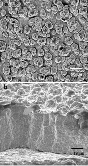
SEM morphologies of both the coating top surface and cross-section surface after fracture, shown in Fig.1, illustrate that the coatings exhibit a granular morphology (Fig.1a), similar to cauliflower formations, as mentioned
Table 1 Suspension plasma spraying (SPS) parameters
Plasma torch F4-VB Sulzer-Metco
Anode diameter, mm 6
Plasma gas Ar/He/H2
Plasma gas flow rate, slim 45/45/3
Arc current, A 700
Feedstock injection Liquid pressure: 3.2 bar
Nozzle diameter: 250lm
Spray distance, mm 40
Plasma gun traverse speed, m/s 1.5
Plasma gun scanning step, mm 5
Deposition cycles 75lm 150
Pre-heating temperature substrate,"C 400
Fig. 1 YSZ coating: a top view of the coating surface. b Cross-section view of the coating after fracture
by VanEvery et al. (Ref 25), as a result of the stacked grains. Some columnar stacking defects are also noticed from the micrograph shown inFig.1b.
Figure2illustrates more detailed SEM micrographs of the cross-section view of the coatings after fracture and allows the observation of a thin columnar layer at the substrate/coating interface, which transforms into a granular morphology as the coating distance from the surface increases. Also, in Fig.2b, it can be noticed that the columnar stacking defects shown in Fig.1b, present Fig. 2 SEM of the cross-section view of the coatings after
fracture: a upper part of the coating, b near the substrate/coating interface. A thin columnar layer followed by a granular layer can be observed
Fig. 3 XRD pattern of YSZ coating in as-sprayed condition
Fig. 4 Detailed X-ray diffraction pattern in the region of the diffraction angles 2H = 87" to 90" for the as-sprayed coating
Fig. 5 Examples of the variation of the mechanical properties vs. indenter displacement for the as-sprayed polished sample, with a roughness (Ra) of 2lm: a elastic modulus, b hardness
Table 2 Analysis by EDS of YSZ coating
% Zr Y O
Weight 59.4 10.1 30.5
across the coating thickness, originated mostly from stacking defects in the columnar layer at the substrate/ coating interface, in agreement with the findings reported in the literature (Ref12,25). The morphologies shown in
Fig.2 have been observed before by different authors (Ref8,12,13), who explained in detail the influence of the operating parameters on the coating architecture. These authors considered that the columnar layer is a result of the stacking process of YSZ splats, when the heat flux is controlled by the difference in temperature between the substrate (pre-heated at 400"C) and the deposited mate-rial, which can usually reach between 700 and 800"C. In these conditions, the columnar layer could act as an insulating layer, delaying the heat flux to the substrate and, therefore, modifying the solidification kinetic of the impacting material. As a consequence, a granular mor-phology is produced since it has been considered that the flattening particles spend a longer time in a molten state where they undergo recoil, allowing the formation of smaller size droplets, due to the high surface energy and surface tension. As a result, porosity and voids are also observed, which decrease with the distance from the coating surface towards the coating/substrate interface. In a recent study, Vert (Ref26) found a value of approxi-mately 12% of porosity for the same coated systems as those investigated in the present work. Also, as shown in
Fig.2a, different particles including unmelted, melted and re-solidified particles can be observed. The presence of these particles is due to variations in the deposition conditions, such as changes in arc voltage, presence of plasma jet fringes, differences in feedstock particle size
distribution, etc., as described by Tingaud et al. (Ref10). As a result, the coating morphology is highly heteroge-neous.
The average roughness (Ra) measured by optical
pro-filometry for all the samples was Ra= 5.9 ± 1.6lm. The
chemical analysis conducted on the initial sample by means of EDS gives the composition of the YSZ coating shown in Table2, indicating that these coatings contain 8% mol. Y2O3.
The X-ray spectrum corresponding to the AS sample (Fig.3) nidicates the presence of both tetragonal and cu-bic phases identified with the XRD patterns PDF2005.4CA:01-070-4436 (cubic phase) and PDF2005.4CA:01-070-4430 (tetragonal phase). No evi-dence of the monoclinic phase was observed. However, the distinction between the tetragonal and cubic phases is really difficult because almost all reflections appear at similar 2H values. Nevertheless, there are particular val-ues for the diffraction angles (87" to 90" and above 130" for CoKa1= 0.1789 nm) in the XRD spectrum that allow an explanation of the difference between these two phases (Ref 27,28).
Figure4illustrates the XRD pattern in the 2H region of 87" to 90", indicating that no doublets corresponding to the tetragonal phase (t) or a very sharp peak, related to the cubic phase (c), are present. The shape of the XRD pattern implies the existence of a mixture of both phases, due to the broad and asymmetric profile, as has been reported elsewhere (Ref 28). According to the yttria percentage in the coating composition of 8% mol., the tetragonal phase could correspond either to an Table 3 Mean values of the elastic modulus and the hardness measured at given indenter displacements for the different coated systems and heat treatments
Coated system Indenter displacement, nm Mean value 500 1000 1500 2000 AS-NP (6lm) E, GPa 34 ± 21 35 ± 18 38 ± 21 44 ± 22 38 HIT, GPa 1.2 ± 0.6 1 ± 0.6 0.9 ± 0.4 0.9 ± 0.4 1 AS-P (1lm) E, GPa 47 ± 21 48 ± 13 47 ± 17 49 ± 19 48 HIT, GPa 1.7 ± 1.1 1.4 ± 0.6 1.3 ± 0.5 1.2 ± 0.7 1.4 AS-P (2lm) E, GPa 33 ± 18 38 ± 13 44 ± 13 48 ± 19 41 HIT, GPa 1.2 ± 0.8 1.0 ± 0.6 1.0 ± 0.4 1.1 ± 0.5 1.1 TT300"C-P (0.5 lm) E, GPa 63 ± 20 64 ± 18 68 ± 19 69 ± 14 66 HIT, GPa 2.2 ± 1.5 2.1 ± 1.3 2.4 ± 1.4 2.4 ± 1.2 2.3 TT300"C-P (1 lm) E, GPa 52 ± 17 45 ± 12 43 ± 14 46 ± 15 46 HIT, GPa 2.2 ± 1.1 1.4 ± 0.5 1.1 ± 0.4 1.0 ± 0.5 1.4 TT600"C-P (2 lm) E, GPa 61 ± 26 55 ± 21 56 ± 20 59 ± 22 58 HIT, GPa 3.0 ± 2.1 2.4 ± 1.5 1.9 ± 1.0 1.8 ± 1.0 2.3 TT600"C-P (3 lm) E, GPa 58 ± 22 45 ± 20 41 ± 18 43 ± 20 47 HIT, GPa 1.9 ± 1.3 1.6 ± 1.2 1.4 ± 0.9 1.4 ± 0.7 1.6
Values inside the parenthesis indicate the roughness (Ra) of the coatings before polishing (NP) and after polishing (P). As-sprayed non polished (AS-NP), as-sprayed polished (AS-P), heat treated at 300"C polished (TT300 "C-P), heat treated at 600 "C polished (TT600 "C-P)
untransformable (t0) tetragonal phase, or to a
non-trans-formable tetragonal phase (t00). The former is a metastable
phase even at high temperature, which does not transform to the monoclinic phase. The latter (t00) has a tetragonality
close to unit, where oxygen atoms are displaced all along c axis from the ideal sites in fluorite cubic phase. Regarding the cubic phase, various authors have identified its presence for the same Y2O3 concentration as that
found in this investigation (Ref29–31).
3.2 Mechanical Properties
As observed from the SEM micrographs presented above, the nanostructured YSZ coating exhibits pores and different types of particles, which have a significant influ-ence on the characterization of the mechanical properties by indentation methods, as shown in below. Figure5
illustrates some examples of the variation in the elastic modulus and hardness as a function of the indenter dis-placement, determined during the indentation experi-ments carried out on the AS polished sample (Ra = 2lm). It should be noted that these figures illustrate the behavior found in all the tests performed during this investigation,
for every sample condition. It is noticeable that the two mechanical properties vary to a large extent with the in-denter displacement for each indentation, which is due to the heterogeneity of the coating. It is important to men-tion that because of the high variamen-tion between the indentations per sample it has been suggested a method-ology to obtain the intrinsic values for the samples studied, that will be presented in next paragraphs (Table3).
In order to explain the behavior of the curves showed in Fig.5, it can be proposed that for the case of test no. 1, if the material is dense or found a region of well-melted particles very close to the top surface, both mechanical properties have a high value close to that reported by Vert et al. (Ref32) for nanostructured YSZ coatings. However, as the indentation depth increases and if the indenter meets a pore or a region of unmelted particles, the apparent values of these mechanical properties can decrease drastically. High properties values for melted and low values for unmelted particles in YSZ nanostruc-tured coatings are mentioned in different investigations (Ref 33,34).
In contrast, for the cases of tests no. 2 and 3 shown in Fig.5, if such unmelted particles and defects are very close to the external surface of the material, the values of the mechanical properties are very low. For these two situa-tions, when the indenter penetrates into the material, the change in hardness with indentation depth can take dif-ferent shapes, according to the nature of particles and the presence of pores located in the neighborhood of the plastic zone below the indenter. Accordingly, as can be observed in Fig.5, an increase or decrease in these mechanical properties will take place, because of the heterogeneity of the coatings. Independent of such varia-tions, it is noted that the evolution of the elastic modulus and hardness with indentation depth exhibits some simi-larities.
As was mentioned previously, the analysis of the actual mechanical properties of the YSZ coating requires a cautious methodology. To circumvent such a problem, it is proposed that the computation of the values of the elastic
Fig. 6 Mechanical properties vs. the roughness for the as sprayed and heat treatment coatings: a elastic modulus, b
modulus and the hardness is carried out at given indenter displacements (500, 1000, 1500 and 2000 nm), as indicated by the doted vertical lines in Fig.5. Subsequently, the mean values and the standard deviations at the mentioned displacements can be calculated considering all the indentations done on each sample (AS, heat-treated, non-polished, polished). The results are summarized in Table3.
Irrespective of the conditions and of the roughness values of the coatings, it is observed that the mean values are nearly constant as a function of the indenter dis-placements, whereas the standard deviation varies to a great extent showing that the material is strongly hetero-geneous and that the measurement of the mechanical properties depends on the nature of particles and the porosity of the coating. If it is assumed that the values of the mechanical properties are independent of the inden-tation depth, because of the similitude between the values obtained at the different indenter displacements indicated previously, the elastic modulus and hardness could be plotted as a function of the roughness, as shown in Fig.6. In Fig.6, it can be observed that the mean mechanical properties summarized in Table3decrease as the coating roughness increases. Jointly with the values indicated in Table3, it is noticeable that the mechanical properties obtained for the coating heat-treated at 600"C have higher values at a given roughness, in comparison with the AS coating and the coating treated at 300"C, whose val-ues varied in a similar manner. These results allow the separation of the three sets of coatings in two different groups, as shown in Fig.6. One group comprises the AS material together with the heat-treated samples at 300"C, where no appreciable difference have been observed in terms of mechanical properties. The second group corre-sponds to the heat-treated coatings at 600"C. In Table3, it can be observed that the AS coating without any prior polishing and heat treatment exhibits the highest rough-ness and has the lowest values of both elastic modulus and hardness. To explain such a variation, an association of the affected zone by the indentation process to the degree of the coating porosity could be made. Thus, it can be as-sumed that polishing leads to a blockage of the pores by the particles resulting from this process. In this case, the indented zone of the material becomes denser and the mechanical properties exhibit higher values, which are related to the nature of the particles (melted or unmelted). In order to represent the variation of both of the elastic modulus and the hardness with roughness, a simple parametric relationship of the form:
P ¼ PR þ Pð M! PRÞ & exp !k & R½ (; ðEq 4Þ
has been suggested. In Eq (4), P represents the elastic modulus or hardness evaluated experimentally, PR is the
initial mechanical property of the coating at high values of Ra (without polishing), PMthe intrinsic mechanical
prop-erty and k a factor related to the curvature of this variation. This factor represents the inverse of the porosity for which the ratio (P! PR)/(PM! PR) = 0.368, that is to say, when
the difference between the measured mechanical property and the mechanical property corresponding to the rough coating achieves approximately 37% of the maximum dif-ference between both parameters, (PM! PR).
Such an approach has been applied to represent the elastic modulus and hardness variation versus the rough-ness, as shown in Fig.6 by the dotted lines, where a sat-isfactory description of the experimental data can be observed. For the fitting, the three parameters, i.e. PR, PM
and k are determined following a free optimization pro-cedure, that is to say, without imposing any restrictions. As a result, it is noted that for the same group of samples the parameter k takes similar values for the elastic mod-ulus and hardness variation, which shows that these two properties tend to vary in a similar manner as observed in
Fig.5. In addition, whatever the condition of the coating, the intrinsic elastic modulus of the corresponding material has a value of approximately 130 GPa as already men-tioned by Vert et al. (Ref 32), who found similar values depending on the thermal spraying conditions.
In the case of the hardness values, it was found that for the AS and heat-treated samples at 300"C, the intrinsic hardness has a value of approximately 5.3 GPa and that this property increased to approximately 6.6 GPa after heat treating the coating at 600"C. These results show that the heat treatment has an effect on the hardness behavior of the material, which could also affect its tri-bological behavior.
3.3 Tribological Features
The evolution of the friction coefficient (l) of the YSZ coatings measured at room temperature and different loads is shown in Fig.7. The average values ofl fluctuate with the normal load applied during the test. At a normal load of 2 N, it was of approximately 0.3, whereas at 5 N it varied between 0.4 and 0.6. At 5 N, the variation of the friction coefficient of the AS and heat-treated samples is noticeable. For all the tested samples and independently of the test loads, the friction coefficient initially decreases
Table 4 Results of the pin-on-disc tests conducted on the YSZ coatings
Condition Temp!C Radius, mm Load, N Sliding distance, m Volume, 108lm3 10STD,7lm3 10213Kw, m3/Nm 10214STD, m3/Nm AS 25 10 2 500 1.0 2.3 1.0 2.3 TT-300"C 1.8 4.0 1.8 4.0 TT-600"C 1.7 5.7 1.7 5.7 AS 6 5 300 2.9 2.3 1.9 1.5 TT-300"C 3.3 1.6 2.2 1.1 TT-600"C 4.1 7.7 2.7 7.7
and then stabilizes as the number of laps increases. It is believed that this behavior is related to the smoothing of the surface, exhibiting a lower roughness (1–3lm). Simi-lar considerations were reported by Ramachandran et al. (Ref35). However, an increase in the friction coefficient with normal load can also be observed as a consequence of
the higher amount of debris generated from the worn surfaces during the sliding wear tests.
The mean worn volumes and wear constants (Kw) are
reported in Table4. The results reveal that the heat treatments have a detrimental effect on the tribological behavior of the samples, especially noticeable for the samples tested at a 5 N normal load, for which the tested coatings have undergone more severe damage in com-parison with those tested at 2 N.
Optical profilometry measurements taken on the wear tracks produced on the coating surfaces after testing under a 2 N normal load revealed slight differences in both wear volumes and wear constant values between the three conditions of the tested samples. Apparently, at 2 N nor-mal load, both heat treatments have a negative effect on the wear resistance of the YSZ. However, for the sample heat-treated at 600"C, which could go through variations in phase composition, as well as in the residual stress values, the wear damage produced in the tests performed at 2 N could be mitigated slightly due to its increase in hardness. Nevertheless, the tests carried out at 5 N have shown that AS and TT-300"C samples had a similar tri-bological response, whereas the coating TT-600"C exhibited the worst wear resistance, as can be seen in Table 4.
The values of the wear constants of the samples tested employing 2 and 5 N normal loads were approximately in the range of 10!13m3/Nm, indicating a smaller wear
resistance of these coatings as compared to the results reported by Darut et al. (Ref 14). These authors found lower wear constants ranging from 3.4 9 10!15 to 1.3 9 10!13m3/Nm at 5 N (20,000 laps) for a porous coating and 10!14m3/Nm for dense YSZ coatings
depos-ited by SPS, tested against an alumina counterpart of 6 mm diameter. Nevertheless, it has to be pointed out that these results corresponded to coatings composed of tetragonal phase only.
The higher wear constants obtained in the present work could therefore be attributed mainly to the presence of a cubic phase in the coating composition, as shown above from the XRD results. The cubic zirconia-based coatings exhibit relatively lower fracture toughness (2.4 MPa m1/2)
(Ref 36, 37), which is generally associated with a lower performance of materials during wear tests. Moreover, the humidity during the test (50 ± 10%) could negatively af-fect the tribological performance of coatings, increasing the wear rate in comparison to the values obtained in a dry nitrogen environment as mentioned in (Ref 19). This could promote intergranular fracture due to embrittle-ment by the chemical adsorption of water, as a conse-quence of the well-known tendency of oxide ceramics to form hydroxylic surfaces (Ref 38–40). The factors men-tioned above counteract the expected good tribological behavior associated with the nanostructure nature of these coatings.
SEM micrographs of the wear tracks and their corre-sponding profiles are shown in Fig. 8 and 9 for normal loads of 2 and 5 N, respectively. The morphology of the wear tracks corresponding to the tests carried out at a 2 N normal load indicates a smoothing of the surface due to Fig. 8 SEM morphology of the wear tracks after the tests
car-ried out at a 2 N normal load and the corresponding linear profile: a as-sprayed, b TT-600"C
the removal of asperities, blocking of pores and formation of islands of compacted and/or smeared wear debris par-ticles, corresponding to the darkest areas on the micro-graphs. Also, smoothing could due to brittle fracture of the material, as a consequence of an abrasive process initially of two bodies and then of three bodies because of the production of debris (see Fig.8).
In the detailed micrograph taken at higher magnifica-tions, corresponding to the sample heat-treated at 600"C
and tested at 2 N, it is interesting to observe the fact that its morphology still shows the presence of some grains corresponding to its initial surface morphology, indicating that a slight increase in hardness probably took place at this temperature, as compared to the other samples con-ditions.
At a 5 N applied normal load, all these processes are intensified and the worn surfaces exhibit a higher amount of abrasive mechanisms coupled with fatigue, owing to the cyclic load applied, therefore leading to severe fracture and grain pull-out with the production of a larger amounts of fine and irregular wear debris over and outside of the tribocontact areas. Under these conditions, the heat treatment at 600"C gives rise to a negative effect on the wear behavior of the YSZ coatings, increasing the size of wear track as shown in Fig.9. The EDS analysis carried out over the surface of the wear tracks identified only the elements corresponding to the YSZ coating (Y, Zr and O). In general, the following wear mechanism could be postulated: during the sliding wear tests the ball or alu-mina counterpart, which is harder than the coating (H = 21 GPa), progressively crushes the grains on the surface, giving rise to the presence of debris due to brittle
Fig. 9 SEM morphology of the wear tracks after the tests car-ried out at a 5 N normal load and the corresponding linear profile, a as-sprayed, b TT-600"C
Fig. 10 Comparison between the XRD patterns for samples as-sprayed and heat treated after the wear tests
Fig. 11 Detailed X-ray diffraction pattern in the region of the diffraction angles 2H = 87" to 90" for the as-sprayed and heat-treated samples after the wear tests
fracture and fatigue. The applied load may induce deco-hesion of particles causing their detachment from the coating and, therefore, becoming a three-body abrasive mechanism (Ref 35). The coating material, removed as debris, could either be ejected from the wear track or could be embedded into it, forming islands of compacted particles adherent in the region of the tribological contact. After this process, grooved wear tracks are formed, as shown by the linear profiles. With the increase in load, the process is intensified and, therefore, the width and depth of the wear tracks increase and a higher amount of debris is observed at the edge of the tracks. The XRD patterns shown inFig.10 correspond to all the worn samples and reveal the presence of only the tetragonal and cubic phases. For higher precision, the XRD pattern was eval-uated in the 2H region between 87" and 90" as indicated in Fig.11. The XRD patterns of the worn sample showed no evidence of the presence of the monoclinic phase, suggesting that no transformation toughening mechanism occurred during the wear test, a result which confirms the presence of non-transformable tetragonal phases (t0+ t00),
as discussed above. (Ref29,30,41,42).
The spectrum of the AS worn sample exhibits a very similar pattern in comparison with that corresponding to the initial AS specimen, since just a small broadening of the principal peak is observed. This behavior is compa-rable to the shape of the pattern corresponding to the sample heat-treated at 300"C, with the difference that the peak at 2H = 88.5" is slightly displaced to the right.
However, from the XRD spectrum corresponding to the TT-600"C sample, it can be observed that all the peaks exhibit a higher broadening, as well as a reduction of their intensities and a slight displacements to the right. The registered modification in all the peak intensities could be related to a variation in crystal structure, i.e. a change in the atomic positions at the unit cell as a con-sequence of thermal vibration. In contrast, the broadening of the peaks could, in general, be associated with a de-crease in the crystallite size and microstrain influenced by non-uniform lattice strain and defects. The displacements to the right could be attributed to a decrease in the lattice parameter and a change in macrostrains, which is a uni-form strain that produces the distortion of the crystal lattice because an imposed external load (Ref 42, 43). These findings could be related to the fact that the sample TT-600"C tested at a 5 N load showed the worst tribo-logical behavior, since it is possible that after the heat treatment some changes in the crystal structure, lattice parameter, microstrain and in the values of the residual stresses could have taken place (Ref43–45)
4. Conclusions
The tribological behavior and mechanical properties of nanostructured 8YSZ coatings deposited by SPS were studied and correlated with their morphological and microstructural characteristics. Also, the influence of the heat treatment at 300 and 600"C on their microstructure and properties were evaluated.
The morphological characterization of the cross-section carried out by MEB revealed that the coatings are com-posed of a thin columnar layer at the interface substrate/ coating, followed by a granular morphology, due to the recoil phenomenon, with the presence of porosity and voids. The XRD analysis revealed the presence of c and t0 + t00 in the AS coating.
The morphology described directly affects the mea-surements of mechanical properties (elastic modulus and hardness) by nanoindentation, which exhibit a consider-able variation due to the coating heterogeneity. It has been shown that the variation of these properties with coating roughness follows an exponential decay law similar for both parameters. The heat treatment carried out at 600"C gave rise to a slight increase in hardness to ~6.5 GPa, as compared to the value of 5.3 GPa determined for the other two conditions: AS and heat-treated at 300"C. However, concerning the modulus of elasticity, an approximate value of 130 GPa was found regardless of the sample condition. Moreover, the tribological characterization resulted in a severe wear regime (>10!4 mm3/Nm) for all the sam-ples under study, as mentioned by Kato and Adachi (Ref
46). The wear volumes and wear constants have revealed that heat treatments conducted at 300 and 600"C had a negative influence on the tribological behavior of the coated systems. The morphology of the wear tracks has shown evidence of brittle fracture in combination with an abrasive wear process and fatigue. These mechanisms are accompanied by the smoothing of the surfaces and blocking of pores, grain pull-out and formation of islands of compacted and/or smeared wear debris.
The obtained severe wear regime could be related to the existence of the cubic phase in the coatings, together with the humidity present during the wear tests (>50%), both of which counteract the expected good tribological behavior associated with the nanostructure nature of the coatings. In addition, the XRD pattern obtained after the tribological tests indicated that heat treatment at 600"C could probably produce changes in crystal structure, as a reduction of the lattice parameter, changes in micro- and macrostrains, a uniform strain that produces the distortion of the crystal lattice because of an imposed external load on the residual stresses. All these variations negatively affected the wear behavior of the coated systems.
Acknowledgements
The present investigation has been carried out with the support of the Scientific and Humanistic Development Council of the Universidad Central de Venezuela (CDCH-UCV) through the Projects No AIB-08-85-39-2012 and PG-08-8645-2013. Ms. S. Kossman gratefully acknowledges the financial support through the scholar-ship ‘‘Stages Master ‘‘received from University of Lille 1 to carry out part of the experiments in LML UST Lille and Arts et Me´tiers ParisTech, MSMP, Lille, France. Professor Puchi acknowledges the financial support of the Conseil Re´gional Nord-Pas de Calais, France through the Inter-national Chair Program 2011.
References
1. J.R. Davis, Protective Coatings for Superalloys. ASM Specially Handbook, Heat-Resistance Materials. ASM International Mate-rials Park, OH. 1997, p 335-344
2. O. Tingaud, R. Etchart-Salas, V. Rat, J.F. Coudert, H. Ageorges, A. Grimaud, A. Denoirjean, P. Fauchais, G. Montavon, N. Caron and S. Alexandre, Suspension Plasma Spraying of Zirconia Coatings: Process and Coating Structure, 18th International Symposium on Plasma Chemistry, Japan, 2007
3. G. Darut, F. Ben-Ettouil, A. Denoirjean, G. Montavon, H. Ageorges, and P. Fauchais, Dry Sliding Behavior of Sub-Micrometer-Sized Suspension Plasma Sprayed Ceramic Oxide Coatings, J. Therm. Spray Technol., 2010, 19(1–2), p 275-285
4. S.C. Tjong and H. Chen, Nanocrystalline Materials and Coatings, Mater. Sci. Eng. R, 2004, 45(1-2), p 1-88
5. Y. Zeng, S.W. Lee, L. Gao, and C.X. Ding, Atmospheric Plasma Sprayed Coatings of Nanostructured Zirconia, J. Eur. Ceram. Soc., 2002, 22(3), p 347-351
6. L. Pawlowski, Finely Grained Nanometric and Submicrometric Coatings by Thermal Spraying, Surf. Coat. Technol., 2008, 202(18), p 4318-4328
7. M. Gell, Application Opportunities for Nonostructured Materials and Coatings, Mater. Sci. Eng., 1995, 204(1), p 246-251 8. P. Fauchais and A. Vardelle, Solution and Suspension
Plasma Spraying of Nanostructured Coatings. In H. Salimi Advanced Thermal Spray Applications, Ed. InTech, 2012, Chapter 7
9. E. Brousse, G. Montavon, P. Fauchais, A. Denoirjean, V. Rat, J.-F.Coudert, and H. Ageorges, Thin and Dense Yttria-Partially Stabilized Zirconia Electrolytes for IT-SOFC Manufactured by Suspension Plasma Spraying, Thermal Spray 2008: Crossing Borders (DVS-ASM), 2008, p 535-540
10. O. Tingaud, A. Grimaud, A. Denoirjean, G. Montavon, V. Rat, J.-F.Coudert, P. Fauchais, and T. Chartier, Suspension Plasma-Sprayed Alumina Coating Structures: Operating Parameters vs. Coating Architecture, Thermal Spray 2008: Crossing Borders (DVS-ASM), 2008, p 311-316
11. L. Pawlowski, Suspension and Solution Thermal Spraying Coat-ings, Surf. Coat. Technol., 2009, 203, p 2807-2829
12. A. Bacciochini, G. Montavon, J. Llavsky, A. Denoirjean, and P. Fauchais, Porous Architecture of SPS Thick YSZ Coatings at the Nanometer Scale (~50 nm), J. Therm. Spray Technol., 2010, 19(1–2), p 198-206
13. R. Vert, P. Carles, E. Meillot, E. Laborde, G. Mariaux, and A. Vardelle, Adhesion of Ceramic Coating on Thin and Smooth Metal Substrate: A Novel Approach with a Nanostructured Ceramic Interlayer, J. Therm. Spray Technol., 2012, 21(6), p 1128-1134
14. G. Darut, H. Ageorges, A. Denoirjean, and P. Fauchais, Tribo-logical Performances of YSZ Composite Coatings Manufactured by Suspension Plasma Spraying, Surf. Coat. Technol., 2013, 217, p 172-180
15. C. Piconi and G. Maccauro, Zirconia as a Ceramic Biomaterial, Biomaterials, 1999, 20, p 1-25
16. R. Hannink, P. Kelly, and B. Muddle, Transformation Tough-ening in Zirconia-Containing Ceramics, J. Am. Ceram. Soc., 2000, 83(3), p 461-487
17. S. Tao, B. Llang, C. Ding, H. Llao, and C. Coddet, Wear Char-acteristics of Plasma-Sprayed Nanostructured Yttria Partially Stabilized Zirconia Coatings, J. Therm. Spray Technol., 2004, 14(4), p 518-523
18. H. Ahn, J. Kim, and D. Lim, Tribological Behavior of Plasma Sprayed Zirconia Coatings, Wear, 1997, 203(204), p 77-87 19. T.E. Fischer, M.P. Anderson, S. Jahanmir, and R. Salher, Friction
and Wear of Tough and Brittle Zirconia in Nitrogen, Air, Water, and Hexadecadene Containing Stearic Acid, Wear, 1988, 124, p 133-148
20. J.H. Ouyang and S. Sasaki, Unlubricated Friction and Wear Behavior of Low-Pressure Plasma-Sprayed ZrO2 Coating at Elevated Temperatures, Ceram. Int., 2001, 27, p 251-260 21. A. Erdemir, A Review of the lubrication of ceramics with thin
solid films. Friction and Wear of Ceramics, S. Jahanmir, Ed., Marcel Dekker, 1994, p 119-161
22. J. Ilavsky and J.K. Stalick, Phase Composition and Its Changes During Annealing of Plasma-Sprayed YSZ, Surf. Coat. Technol., 2000, 127, p 120-129
23. W.C. Oliver and G.M. Pharr, Improved Technique for Deter-mining Hardness and Elastic Modulus Using Load and Dis-placement Sensing Indentation Experiments, J. Mater. Res., 1992, 7(6), p 1564-1580
24. W.C. Oliver and G.M. Pharr, Measurement of Hardness and Elastic Modulus by Instrumented Indentation: Advances in Understanding and Refinements to Methodology, J. Mater. Res., 2004, 19(1), p 3-20
25. K. VanEvery, M. Krane, R. Trice, H. Wang, W. Porter, M. Besser, D. Sordelet, J. Ilavsky, and J. Almer, Column Formation in Suspension Plasma-Sprayed Coatings and Resultant Thermal Properties, J. Therm. Spray Technol., 2011, 20, p 817-828 26. R. Vert, Elaboration Par Projection Plasma d!un reveˆtement
ce´ramique sur un substrat me´tallique mince et de faible rugosite´ : Usage d!une sous-couche d!adhe´rence nanostructure´e. PhD the-sis, Universite´ de Limoges, 2011, (in French)
27. D.N. Argyriou and C.J. Howard, Reinvestigation of Yttria-Tetragonal Zirconia Polycrystal (Y-TZP) by Neutron Powder Diffraction—A Cautionary Tale, J. Appl. Crystallogr., 1995, 28, p 206-208
28. R. Srinivasan, R. De Angelis, G. Ice, and B. Davis, Identification of Tetragonal and Cubic Structures of Zirconia Using Synchrotron X-Radiation Source, J. Mater. Res., 1991, 6, p 1287-1292
29. J. Swab, Role of Oxide Additives in Stabilizing Zirconia for Coating Applications, Army Research Laboratory, 2001, ARL-TR-2591
30. X. Xing, Thesis: Computational modeling study of yttria stabilized zirconia. PhD thesis. University College of London, 2010 31. S. Giraud and J. Canel, Young!s Modulus of Some SOFCs
Materials as a Function of Temperature, J. Eur. Ceram. Soc., 2008, 28, p 77-83
32. R. Vert, D. Chicot, C. Dublanche-Tixier, E. Meillot, A. Vardelle, and G. Mariaux, Adhesion of YSZ Suspension Plasma-Sprayed Coating on Smooth and Thin Substrates, Surf. Coat. Technol., 2010,205, p 999-1003
33. R.S. Lima, A. Kucuk, and C.C. Berndt, Bimodal Distribution of Mechanical Properties on Plasma Sprayed Nanostructured Par-tially Stabilized Zirconia, Mater. Sci. Eng., 2002, A327, p 224-232 34. P. Carpio, E. Rayo´n, L. Pawłowski, A. Cattini, R. Benavente, E. Bannier, M.D. Salvador, and E. Sa´nchez, Microstructure and Indentation Mechanical Properties of YSZ Nanostructured Coatings Obtained by Suspension Plasma Spraying, Surf. Coat. Technol., 2013, 220, p 237-243
35. C.S. Ramachandran, V. Balasubramanian, P.V. Ananthapadma-nabhan, and V. Viswabaskaran, Understanding the Dry Sliding Wear Behaviour of Atmospheric Plasma-Sprayed Rare Earth Oxide Coatings, Mater. Des., 2012, 39, p 234-252
36. S. Jahanmir, Advanced Ceramics in Tribological Applications. Friction and Wear of Ceramics, S. Jahanmir, Ed., Marcel Dekker, 1994, p 3-12
37. S.T. Aruna, N. Balaji, and K.S. Rajam, Phase Transformation and Wear Studies of Plasma Sprayed Yttria Stabilized Zirconia Coatings Containing Various mol% of Yttria, Mater. Charact., 2011, 62, p 697-705
38. S.M. Wiederhorn, S.W. Freiman, E.R. Fuller, and C.J. Simmons, Effect of Water and Other Dielectrics on Crack Growth, J. Mater. Sci., 1982, 17, p 3460-3478
39. T.A. Michalske and B.C. Bunker, Slow Fracture Model Based on Strained Silicate Structures, J. Appl. Phys., 1984, 56, p 2686
40. R.K. Iler, The Chemistry of Silica, Wiley, New York, 1979, p 896 41. S. Nazarpour, C. Lo´pez-Ga´ndaraa, C. Zamania, J.M. Ferna´ndez-Sanjua´n, F. Ramos, and A. Cirera, Phase Transformation Studies on YSZ Doped with Alumina. Part 2: Yttria Segregation, J. Al-loys Compd., 2010, 505, p 534-554
42. G. Witz, V. Shklover, W. Steurer, S. Bachegowda, and H. Boss-mann, Phase Evolution in Yttria-Stabilized Zirconia Thermal Barrier Coatings Studied by Rietveld Refinement of X-Ray Powder Diffraction Patterns, J. Am. Ceram. Soc., 2007, 90(9), p 2935-2940
43. B.D. Cullity, Elements of X-Ray Diffraction, 2nd ed., Addison-Wesley, Boston, 1978
44. S. Kuroda, T. Dendo, and S. Kitahara, Quenching Stress in Plasma Sprayed Coatings and Its Correlation with Deposit Microstructure, J. Therm. Spray Technol., 1995, 4(1), p 75-84 45. A. Macwan. Residual Stresses in Suspension Plasma Sprayed
Electrolytes in Metal-Supported Solid Oxide Fuel Cell. Master thesis. Ryerson University, Canada, 2012
46. K. Kato and K. Adachi, Wear Mechanisms. Modern Tribology Handbook Vol. I, B. Bhushan, CRC, 2001, Chapter 7