The Living Light Conference 2016
Sol-gel molding: a new observation method of multiscaled
structures
M. Thomé
a*, L. Nicole
b, S. Berthier
a,c aInstitut des NanoSciences de Paris, UMR 7588, 4 Place Jussieu, 75005 Paris, France. b
Sorbonne Universités, UPMC Univ Paris 06, UMR 7574, Chimie de la Matière Condensée de Paris, 75005 Paris, France. c
Université Paris Diderot, 5 rue Thomas-Mann, 75013 Paris, France.
Abstract
During the twentieth century, many new methods have been developed to observe the structuration of matter. This development was necessary in particular to study new scales: the microscopic and nanoscopic ones. Electronic microscopes, X-Ray tomography, and other tools allowed, for example in materials science, to discover new structures and their associated properties. Several of these methods are also often used to characterize the same sample, providing different complementary information and improving the knowledge of the sample. In this paper, we propose to underline another complementary way to study in details the structuration of a material. This way is to make an inverse replica, in other words a molding of the studied structure. Our method consists, more precisely, in using a sol-gel solution deposition technique and can reveal details that are difficult to see with microscopes. It is particularly well adapted to nanostructured and/or multiscaled materials. As an example, a molding of a
Morpho menelaus butterfly wing is presented. It highlights the periodicity of the smallest and often neglected structure of the
wing: the microribs.
.
Keywords: sol-gel process ; Morpho butterfly wing ; replicas ; photonic structures ; characterization method ; microribs
* Corresponding author. Tel.: +33 1 44 27 40 85 ; fax: +33 1 44 27 39 82. E-mail address: [email protected]
1. Introduction
Currently, many techniques are used to explore the three-dimensional structure of an object. Most of these are microscopes developed during the twentieth century: for example, the Scanning Electron Microscope (SEM) in the 1960s, and the Atomic Force Microscope (AFM) or the Scanning Tunneling Microscope (STM) in the 1980s. Additional handling is sometimes required as well: for instance, some 3D complex objects have to be broken in order to reveal hidden structures inside the object and hardly discernible with microscopes. These broken samples are then easier to turn in all directions and we can see more clearly some details of the structure. The different points of view resulting from all these techniques are often compared and provide a detailed shape of the studied object. This comparison is even more necessary that the object structure is complex and multiscaled.
In this paper, we present another way to study the structuration of matter and to have more information especially about the nanometric shape details. This way is to make an inverse replica, i.e. a molding of the studied structure, using a sol-gel solution deposition method. This replication method is easy to implement and can be used as a complement to microscopy techniques and to the breaking process mentioned above. It also allows highlighting « hidden » micrometric or nanometric sub-structures. First, we propose to describe the method and the general experimental protocol. Then, we validate its relevancy with an example of a molding of Morpho menelaus butterfly wing scales. We particularly discuss the highlighting of the smallest structure in the wing: the microribs.
2. The sol-gel deposition molding method
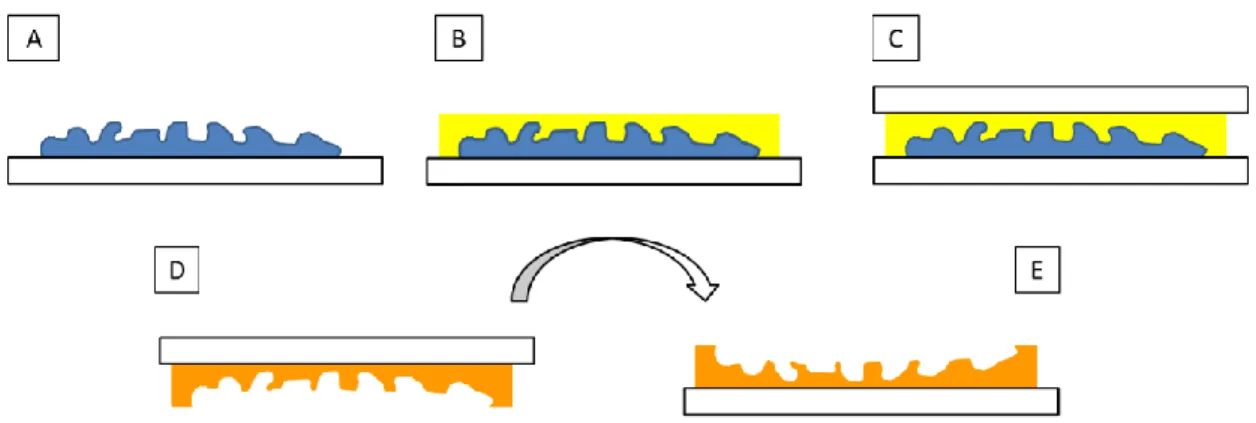
To achieve a molding of a complex structure, we propose in this paper a method based on a chemical solution deposition using a sol-gel process (Figure 1). More precisely, the deposited solution of precursors contains titanium n-propoxide, acetylacetone (acac) and ethanol (EtOH) as solvent. The corresponding molar ratio is: 1 Ti : 1 acac : 20 EtOH. An addition of a commercial suspension of silica nanoparticles, called Ludox AM30, is also made and equal to 5% weight of Ti. This addition is useful to limit the classic cracking phenomenon during a sol-gel condensation and to relax the network constraints. The studied structure is first deposited on a glass slide (Fig. 1.A). Then, at room temperature (i.e. 20°C) and room relative humidity (i.e. 45%), the liquid solution is dropped into the structure with a Pasteur pipet until its complete filling (Fig. 1.B). Quickly after the filling, a second glass slide is deposited on the structure and the combination thus formed is aging between 2 and 5 days at 35°C and 25% of relative humidity (Fig. 1.C). The second glass slide will be the support of the molding once the studied organic structure eliminated (Fig. 1.D and 1.E). The molding can be then characterized and observed using electronic microscopes, AFM, X-Ray, etc. and is likely to provide new interesting information.
Fig. 1. Main steps of the manufacturing of a molding using our sol-gel solution deposition method: (A) First, the studied structure (in blue) is deposited on a glass slide (in white); (B) Then, at room temperature (20°C) and room relative humidity (45%), the sol-gel solution (in yellow) is dropped inside the structure until its complete filling; (C) After filling, another glass slide is deposited on the unit “structure + sol-gel solution” and this set is aging at 35°C and 25% of relative humidity between two and five days; (D) Finally, the initial structure is eliminated; the first glass slide breaks off and the molding (inverse replica, in orange) is released; (E) To observe the molding, it has just to be turned.
3. Example of a Morpho menelaus wing structure molding
3.1. Presentation of the natural studied structure
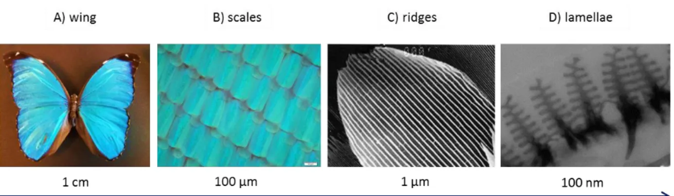
We have chosen to replicate a Morpho menelaus butterfly wing (Figure 2). The structure of the Morpho blue wings is particularly studied in recent years, due to its multiscaled and multifunctional features [1-4]. Indeed, this structure is composed of several sub-structures, which all participate in the origin of the functions (properties) of the wing. The wing is covered with scales (100 µm length and 50 µm width) (Fig. 2.B) and there are two different types of scales: the transparent cover scales and the blue ground ones. Researchers are more interested in the blue ground scales because of the photonic origin of this blue color. Each scale is covered with a lattice of ridges (600 nm apart for the blue ground scales and about 1 µm apart for the transparent cover scales) (Fig. 2.C) and one ridge is a stack of lamellae (about 50 nm thick) (Fig. 2.D). As a multilayer (with a 100 nm period), the stack of lamellae selects a blue color by interferences, and the lattice of ridges scatters this blue light by diffraction. The period sizes of these two periodic lattices are particularly suitable to perform the blue reflection. Hence, the blue color doesn’t originate from a blue pigment but is created by the physical shape of the wing (mainly by the nanometric dimension of the lamellae). Such a color is called “structural”.
The nanometric scale then provides the colorimetric property, and the micrometric one (i.e. all the types of scales and the ridges) lead to the super-hydrophobicity of the wing. As other properties of this multifunctional structure, we can also mention a thermal control and the flying ability [5].
Finally, the last periodic structure of the wing is the lattice of the inter-lamellae membranes, called “microribs” by Ghiradella in 1989 [6]. Figure 3.A shows a side view of a ridge and, in particular, the periodic microribs (30 nm thick) delineating shallow cavities (60-100 nm width). The function of these small membranes is not currently known and, to our knowledge, the work of Lee and al. [7] is the only one presenting a study of their potential role. They investigated the scattered light of a 3D model of a Morpho rhetenor wing using Finite-Difference Time-Domain (FDTD) method. They focused their work on iridescence (color changing with angle of incidence) and on the impact of the microribs on the reflected color by the wing. Regarding this reflected optical response, they don’t show a particular photonic role of the microribs.
Fig. 2. Multiscaled Morpho menelaus structure: (A) Dorsal side of a Morpho menelaus male; (B) Magnification of the wing surface using an optical microscope: we can see scales arranged like roof tiles; (C) Each scale is covered with a lattice of ridges (SEM image); (D) The cross-section of the ridges results in the observation of Christmas tree shapes whose each branch correspond to a lamella (Transmission Electron Microscopy image).
Fig. 3. (A) This SEM image shows a side view of a ridge, corresponding to a view in the -y direction of the right schematic representation (B). We see the stack of lamellae and the microribs, which are the small membranes perpendicularly located between the lamellae; (B) Schematic representation of the cross-section of three ridges. The Christmas tree shapes (cited in the Fig. 2 caption) are visible in the foreground, the lamellae (in light grey) run along the x direction and the microribs are represented in dark grey.
3.2. Precisions about our Morpho wing molding
We were interested in the molding of the ground blue scales. To make this inverse replica, the butterfly wing has to be deposited on a glass slide with its blue side up. As mentioned above, the used titania-based solution is dropped on the wing with a Pasteur pipet until it complete filling, that is to say, for this sample, until the blue color changes to brown. In fact, due to the similar value (n550~1,63) of the refractive indices of the solution and the chitin-proteins complex (which constitutes the wing), the interferences phenomena mainly produced by interaction with lamellae disappear. The two materials can be considered as only one with the same refractive index and the light similarly propagates through the two materials until the scales and wing membranes. The blue extinction proves the total wing structure infilling by the solution and the brown color of the scales and wing membranes becomes then visible. After the aging step, the natural organic wing has to be also eliminated and in order to release the molding, a heating treatment is done in an oven until 500°C with a 2°C/min ramp.
In a previous article [8], we have also presented a first sol-gel deposition method of butterfly wing replication close to this method. Their similar advantages and disadvantages are discussed in there, but we can mention some of them. First, the compatibility of their deposition conditions (room temperature and ambient temperature) with the intrinsic fragility of the wing is important to preserve the initial studied structure during all the replication steps. The liquid state of the deposited material (i.e. the sol-gel solution) resulting in an impregnation of the fine structure by capillarity also participates in a higher fidelity of the shape-replication. Finally, the shorter or longer aging times, necessary to promote the controlled hydrolysis-condensation reactions resulting in the TiO2 material, can be inconvenient and the cracking phenomenon appearing during the sol-gel condensation (previously mentioned) can lead to a fragility of the replica. Another deposition technique is cited as well: the physical vapor deposition (PVD). This can be used instead of the sol-gel technique to faster replicate less complex and fragile structures. Indeed, the PVD method is particularly suitable for replicating 1D and 2D opened structures and doesn’t need aging times as the sol-gel deposition method.
3.3. Results and observations
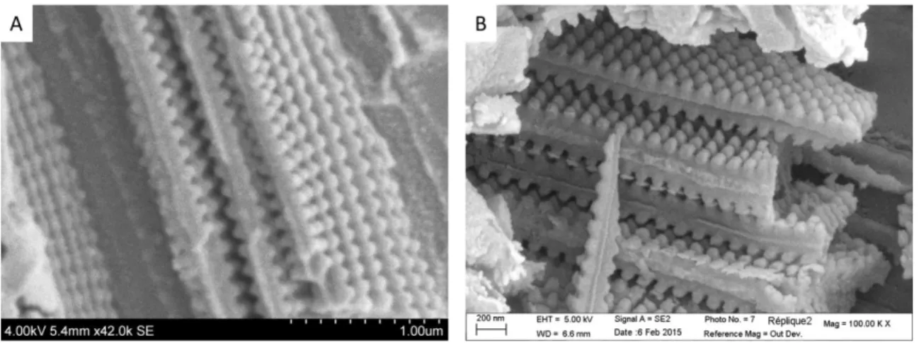
The Figure 4 shows two SEM images of our Morpho menelaus blue scales moldings. We observe top views of some ridges inverse replicas and we can see, in particular, the lattice of semi-spherical protuberances on their sides. These protuberances correspond to the inverse replicas of the cavities delineated by the microribs. The inverse lamellae shapes are less visible than the inverse microribs shapes due to the orientation of the sample relative to the electron beam of the SEM (top views).
From these ridges replicas, the depth of the cavities delineated by the microribs appears significant. The impressive regularity of the microribs lattice (apparently a square lattice) is also highly visible through the protuberances replicas arrangement. Furthermore, it seems that this quasi perfect lattice is the most regular one of the multiscaled wing structure. Then, we can also mention that the shape of these cavities is clearly hemispherical. This hemispherical shape could be seen as the result of the self-shaping of the solvent to minimize the surface energy in the cavities but such a shape seems consistent with the general rounded geometry of all the natural sub-structures of the wing. Neither sub-structure is perfectly angled. It is also consistent with the cross-section shape of the natural cavities observed using a Transmission Electron Microscope (TEM). Indeed, Figure 5 shows a comparison between the rounded shape of the protuberances of a replica (Fig. 5.A) and a TEM image of the blue ridge cross-section of a Morpho menelaus (Fig. 5.B). The cross-section of the bottom of the natural cavities appears hemispherical, as it is pointed by the black circle in Fig. 5.B. By comparison, a black circle underlines also the shape of one hemispherical protuberance in Fig. 5.A. In both pictures, black arrows pointed the spaces corresponding to the microribs depth. Thus, these arguments result in a very likely fidelity of the shape replication using our sol-gel deposition method. Furthermore, this method provides 3D structures (i.e. 3D shape information) and then is complementary to SEM and TEM images of these structures.
Fig. 4. Morpho menelaus wing inverse replicas (top views): the replica of three ridges is shown in (A) and of four ridges in (B). The inverse lamellae structure is less visible on these images because the orientation of the replicas is not really suitable to see clearly the shape of this inverse lamellae structure. However, we clearly observe the moldings of the inter-lamellae cavities, which appear as semi-spherical protuberances on the sides of each ridge replica. These protuberances are arranged as a lattice.
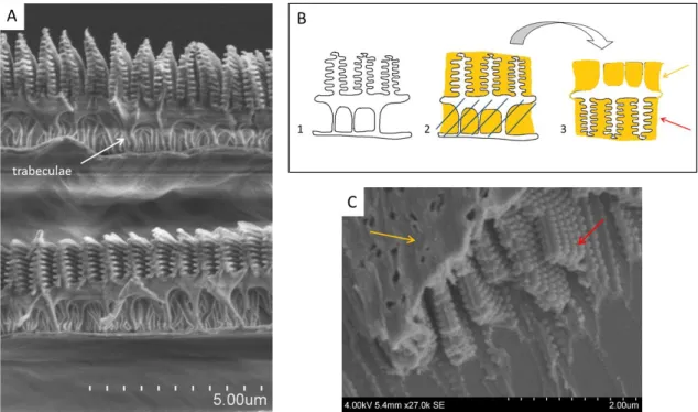
Another structuration detail of the wing is highlighted by the replicas shape. In fact, the ridges are linked to the scale membrane by micrometric pillars called trabeculae which are visible in Figure 6.A. However, on SEM images, it is difficult to see the exact positions of these trabeculae in relation to each other, due to their 3-dimensional location on the scale membrane. Our replication method allows determining precisely these positions. In fact, the Figure 6.B shows a more detailed schematic drawing of the different steps of replication compared to the Figure 1 representation. It represents the cross-section of the natural scale structure (Fig. 6.B.1) for the main steps. The sol-gel solution infiltrates all the parts of the natural wing structure, not only the space between the ridges, but also the space between the bottom of the ridges and the scale membrane (Fig. 6.B.2). After aging and removing the natural
wing by heating in an oven, it results in a molding of this space, in addition to the ridges molding (Fig. 6.B.3). The Figures 4, 6.C, and 7 correspond to SEM images of our Morpho menelaus blue scales moldings. More precisely, Figures 4.A and 4.B only show the ridges and microribs inverse moldings while Figure 6.C, 7.A and 7.B show both ridges and microribs inverse moldings and trabeculae inverse moldings. Indeed, the holes seen on the titania layers pointed by the orange arrows on Fig. 6 and Fig. 7 correspond to the trabeculae inverse moldings, in other words the locations of the trabeculae to each other. It appears that a real disorder characterizes the trabeculae arrangement.
Fig. 5. Comparison between the shape of a replica of a Morpho menelaus blue ridge (A) and a TEM image of the cross-section of the Morpho menelaus natural blue ridge (B). The rounded shape of a cavity replica (protuberance) is circled in (A). The bottom of the cavities appears thus rounded. Such a shape can be suggested by the ridges cross-section TEM images, as we can see in (B). In Fig. 5.B the black circle underlines the rounded shape of a cavity bottom cross-section. Cross-sections of microribs are also visible on TEM images: a microrib is striped inside the black circle of (B). The depths of two other microribs are highlighted by black arrows in Fig. 5.B and their associated replicas depths are marked by black arrows in Fig. 5.A.
4. Discussion
Our method results in detailed moldings. The used sol-gel solution perfectly penetrates in all of the wing structures, mainly thanks to capillarity phenomena. Nanometric structures (lamellae and microribs) seem to be particularly well molded.
Such a detailed Morpho replica has never been presented in literature before. In fact, most of butterfly wings replication works in last years relate to species different from Morpho menelaus or to pigmentary scales, which have less complex structures. Some of these works result also in positive replicas achieved with small quantities of matter: for example, thin layers of TiO2 or Al2O3 are deposited using Atomic Layer Deposition method (ALD) [9, 10], and ZnO, ZrO2, TiO2 or BiFeO3 precursors infiltrate a structure by its immersion in the associated precursors solutions [11-16]. At the opposite, our sol-gel deposition method, or the nanoimprint technique [17] and the molding lithography [18], result in solid inverse replicas of the butterfly wing structure. However, it seems to be more difficult to replicate in details a complex and hierarchical structure with the two last mentioned methods, using both polydimethysiloxane (PDMS). Thanks to our method, the exact structure can be replicated including the typical structural disorder. This disorder seems to play an important role on the macroscopic optical response of the Morpho blue wings: according to recent studies [19-21], it could be in fact the origin of the constraint blue iridescence of the wing. Other different techniques are also used to fabricate directly the Morpho ridges structures (as Focused-Ion-Beam Chemical-Vapor-Deposition (FIB-CVD) [22] or electron beam lithography [23]), but despite of their high precision, the associated replicas don’t reproduce the disorder.
Fig. 6. (A) SEM image of the cross-section of two overlapped Morpho cypris scales: the trabeculae are clearly visible and pointed by a white arrow; (B) Reminder of the different molding process steps applied to a Morpho blue scale: 1. Schematic representation of the cross-section of a natural scale; 2. The sol-gel solution (in orange) penetrates in all the structures and after aging, the butterfly wing is eliminated by heating in an oven; 3. Finally, the molding is turned to reveal a holed titania layer, corresponding to the trabeculae inverse replica (pointed by orange arrows in (B) and (C)), just over the ridges moldings (pointed by red arrows); (C) SEM image of a Morpho menelaus blue scale molding whose schematic representation is Fig. 6.B.3. From this picture, it is possible to see how are located the trabeculae to each other.
Fig. 7. Top views of moldings of Morpho menelaus blue scales. The orange arrows point the holed layers which correspond to the trabeculae inverse replicas. Below these layers appear the ridges inverse replicas pointed by the red arrows. They are the first solid inverse replicas of Morpho menelaus blue scales structures compared to the replicas presented in literature. We can also mention that the cross-section of the ridges molding (B) seems very similar to that natural rigdes one (Fig. 2.D).
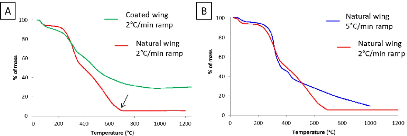
Except in the FIB-CVD and the e-beam lithography, the natural wing is used as a sacrificial template and it has to be eliminated. We have chosen to burn the coated wing in an oven until 500°C with a 2°C/min ramp. In literature, a temperature comprised between 450°C and 500°C [12, 14, 24], and a ramp between 1°C/min and 10°C/min are often cited [12, 25]. During our experiments, we have often noted that some natural organic matter still stays on the titania replicas, even after heating until 500°C. This residual of organic matter can be really annoying for studying the exact structure of the replica. Hence, we have made ThermoGravimetric Analysis (TGA) to quantify the burning of a natural wing and a coated wing with our sol-gel deposition (Figure 8.A) in order to understand why this residual exists. According to the end of the mass losses of these TGA, it results that the minimum temperature to remove all the organic material has to be 700°C for a natural wing (pointed by the black arrow in Fig. 8.A) and seems to be about 800°C for a coated wing. Such high surprising temperatures have already been mentioned in literature to release a replica: it was 800°C in [9] and 700°C in [25]. To our knowledge, only these two papers can be cited. The TGA of the coated wing shows also a 35% mass percent remaining after a complete burning: this mass probably corresponds to the titania replica mass. Then, we made a comparison between a 2°C/min ramp and a 5°C/min one, shown in Figure 8.B. It appears that a 2°C/min ramp is better than 5°C/min to totally eliminate the wing.
Fig. 8. ThermoGravimetric Analysis (TGA) of our samples. Each sample corresponds to one wing and is cut using scissors: (A) Comparison between the TGA of a natural Morpho menelaus wing (red curve) and a coated one with our titania precursors solution (green curve). We can first observe that the burning is complete only at 700°C (pointed by the black arrow) for the natural wing. Regarding the coated wing, the burning seems to be complete around 800-900°C, these values corresponding to the end of the mass loss. After the coated wing burning, we can also see that it remains a mass percent (35%) which is probably the titania replica mass; (B) Comparison between a 2°C/min ramp TGA (red curve) and a 5°C/min ramp TGA (blue curve) of a natural wing. The end of the wing burning happens faster using a 2°C/min ramp than with a 5°C/min ramp.
As cited before, we have finally chosen a burning temperature of 500°C, which is less than the requisite 700°C or 800°C temperatures. This choice is due to the development of new cracking phenomena inside the wing titania coating as a result of the high final temperature. This development seems to increase with the final temperature value. Even if we have added a suspension of silica nanoparticles (Ludox AM30) to the precursors initial solution, it was not sufficient to stop all the cracking phenomena. This temperature impact and the important capillarity stresses inherent in sol-gel process [26] possibly involve the small sizes of the obtained replicas. It can also explain the encountered adhesion problems on the glass slide. For instance, our sol-gel moldings sizes are comprised between about 50 µm² for a Morpho menelaus scale replica and 20 000 µm² concerning a Cicada orni wing replica (characterized by a simpler 2D structure). It thus appears that the replica sizes, obtained with our method, depend on the studied structures.
Then, although we don’t have made a whole wing molding, the achieved surfaces are sufficient to see interesting structural details. The observation of the depth of the cavities underlined by microribs, or the position of trabeculae to each other, are examples of such structural details. Regarding the microribs, their impressive periodicity have then lead us to wonder about their role in the structure and we have begun to study using
calculations the propagation of light through the microribs direction (x direction in the Fig. 3.B). This work should be presented in a few months.
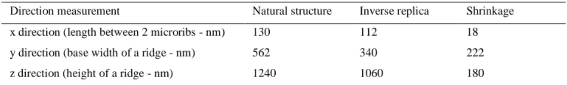
Finally, we have to note that the information gained afterwards the replica study is not perfectly quantitative. Due to the shrinkage phenomenon emerging during the aging step because of the condensation of the sol-gel solution [26], the replicated lengths are decreased compared to the natural ones. More precisely, measurements on replica SEM images presented in this paper and on no presented SEM images of natural Morpho menelaus scales show that the main shrinkage is on the y direction shown in Fig. 3.B. Indeed, the natural ridges width value is decreased by roughly half. The shrinkage on the x direction is of about 18 nm (or one seventh of the length between two microribs) and the shrinkage on the z direction is of about 180 nm (or one seventh of a ridge height). The length measurements and associated shrinkages are reported in Table 1. It should be still noted that measurements concerning the structure on the z direction are less accurate than the ones concerning the other directions, because of the perpendicular location of the replicated ridges under the electron beam. All quantitative information deduced from these replicas have thus to be cited with caution.
Table 1. Lengths measurements of natural and replicated scale structures
Direction measurement Natural structure Inverse replica Shrinkage x direction (length between 2 microribs - nm) 130 112 18 y direction (base width of a ridge - nm) 562 340 222 z direction (height of a ridge - nm) 1240 1060 180
Table 1. The lengths values of natural and replicated scale structures presented in this table are measured on SEM and TEM images. The presented values are averaged from several measurements, except the shrinkage values which are the difference between the natural structure length and the associated inverse replica length.
5. Conclusion
Making inverse replicas appears in this paper as a new way to see easily the nanoscale details of complex surfaces, and in particular, of multiscale natural structures. For example, new points of view on the microribs or the trabeculae have been shown thanks to our Morpho menelaus blue scales moldings. The information obtained from the moldings can be compared to the microscopy images of their templates and allow to discover new structuration or to improve the knowledge on these templates. The presented replication method is also easy to implement and we recommend it especially for studying opened hierarchical structures, whether natural or manufactured.
Acknowledgments
This work was supported by the Cluster of Excellence MATISSE.
References
[1] L. P. Biro, J.-P. Vigneron, Laser & Photonics Reviews, 5 (2011) 27-51.
[2] S. Niu, B. Li, Z. Mu, M. Yang, J. Zhang, Z. Han, L. Ren, Journal of Bionic Engineering, 12 (2015) 170-189. [3] G. S. Smith, American Journal of Physics, 77 (2009) 1010-1019.
[4] S. Yoshioka, S. Kinoshita, Proceedings of the Royal Society B, 273 (2006) 129-134. [5] S. Berthier, Photonique des Morphos, Springer-Verlag, Paris, 2010.
[6] H. Ghiradella, Journal of Morphology, 202 (1989) 69-88. [7] R. T. Lee, G. S. Smith, Applied Optics, 48 (2009) 4177-4190.
[8] M. Thomé, L. Nicole, S. Berthier, Materials Today: Proceedings, 1 (2014) 221-224. [9] J. Huang, X. Wang, Z. L. Wang, Nano Letters, 6 (10) (2006) 2325-2331.
[10] D. P. Gaillot, O. Deparis, V. Welch, B. K. Wagner, J.-P. Vigneron, C. J. Summers, Physical Review E, 78 (3) (2008) 031922. [11] W. Zhang, D. Zhang, T. Fan, J. Ding, Q. Guo, H. Ogawa, Microporous and Mesoporous Materials, 92 (2006) 227-233. [12] W. Zhang, D. Zhang, T. Fan, J. Ding, J. Gu, Q. Guo, H. Ogawa, Bioinspiration and Biomimetics, 1 (2006) 89-95. [13] Y. Chen, J. Gu, S. Zhu, T. Fan, D. Zhang, Q. Guo, Applied Physics Letters, 94 (2009) 053901.
[14] S. Zhu, D. Zhang, Z. Chen, J. Gu, W. Li, H. Jiang, G. Zhou, Nanotechnology, 20 (2009) 315303. [15] X. Liu, S. Zhu, D. Zhang, Z. Chen, Materials Letters, 64 (2010) 2745-2747.
[16] H. Liu, Y. Guo, B. Guo, W. Dong, D. Zhang, Journal of the European Ceramic Society, 32 (2012) 4335-4340.
[17] T. Saison, C. Peroz, V. Chauveau, S. Berthier, E. Sondergard, H. Arribart, Bioinspiration & Biomimetics, 3 (2008) 046004. [18] S.H. Kang, T.Y. Tai, T.H. Fang, Current Applied Physics, 10 (2010) 625-630.
[19] J. Boulenguez, S. Berthier, F. Leroy, Applied Physics A, 106 (2012) 1005-1011. [20] B. Song, S. C. Eom, J. H. Shin, Optics Express, 22 (2014) 19386-19400.
[21] A. Saito, M. Yonezawa, J. Murase, S. Juodkazis, V. Mizeikis, M. Akai-Kasaya, Y. Kuwahara, Journal of Nanoscience and Nanotechnology, 11 (2011) 2785-2792.
[22] K. Watanabe, T. Hoshino, K. Kanda, Y. Haruyama, S. Matsui, Japanese Journal of Applied Physics, 44 (2005) L48-L50.
[23] R. A. Potyrailo, R. K. Bonam, J. G. Hartley, T. A. Starkey, P. Vukusic, M. Vasudev, T. Bunning, R. R. Naik, Z. Tang, M. A. Palacios, M. Larsen, L. A. Le Tarte, J. C. Grande, S. Zhong, T. Deng, Nature Communications, 6 (2015) 7959.
[24] G. Cook, P. L. Timms, C. Göltner-Spickermann, Angewandte Chemie International Edition, 42 (5) (2003) 557-559. [25] J. Silver, R. Withnall, T. G. Ireland, G. R. Fern, Journal of Modern Optics, 52 (7) (2005) 999-1007.