Publisher’s version / Version de l'éditeur:
Vous avez des questions? Nous pouvons vous aider. Pour communiquer directement avec un auteur, consultez la première page de la revue dans laquelle son article a été publié afin de trouver ses coordonnées. Si vous n’arrivez pas à les repérer, communiquez avec nous à PublicationsArchive-ArchivesPublications@nrc-cnrc.gc.ca.
Questions? Contact the NRC Publications Archive team at
PublicationsArchive-ArchivesPublications@nrc-cnrc.gc.ca. If you wish to email the authors directly, please see the first page of the publication for their contact information.
https://publications-cnrc.canada.ca/fra/droits
L’accès à ce site Web et l’utilisation de son contenu sont assujettis aux conditions présentées dans le site LISEZ CES CONDITIONS ATTENTIVEMENT AVANT D’UTILISER CE SITE WEB.
Technical Translation (National Research Council of Canada), 1968
READ THESE TERMS AND CONDITIONS CAREFULLY BEFORE USING THIS WEBSITE.
https://nrc-publications.canada.ca/eng/copyright
NRC Publications Archive Record / Notice des Archives des publications du CNRC :
https://nrc-publications.canada.ca/eng/view/object/?id=e1569f36-5a35-4b07-ae7c-02bed3a1af48 https://publications-cnrc.canada.ca/fra/voir/objet/?id=e1569f36-5a35-4b07-ae7c-02bed3a1af48
Archives des publications du CNRC
For the publisher’s version, please access the DOI link below./ Pour consulter la version de l’éditeur, utilisez le lien DOI ci-dessous.
https://doi.org/10.4224/20375515
Access and use of this website and the material on it are subject to the Terms and Conditions set forth at
Guide for design and construction of pile foundations in permafrost
This translation of the Soviet bUilding code dealing with the design of pile foundations for permafrost areas is of particular interest to the Division of Building Research in its investigations of permafrost and bUilding problems in northern
Canada. The U.S.S.R. has been involved in
construc-tion on permafrost for many years in Siberia and experiences in that country are of great interest to
those who are involved in this 。セエゥカゥエケ in northern
Canada. There is no similar building code available
in Canada at present.
This is the third Russian bUilding code for construction in permafrost regions which has been translated for the Division of Building Research. The first, which deals with the design of all types of foundations for permafrost areas, was issued in
1963 (TT-1033). The second, dealing with the design
of foundations for discontinuous permafrost areas, was issued in 1967 (TT-1298).
Comments upon the contents of this translation from any who have had experience with building in permafrost areas will be welcomed by the Division. Such mUtual exchange of information will be of great assistance to the Division in its task of providing essential information, especially upon unusual build-ing problems for use of the entire buildbuild-ing industry of Canada.
The translation has been prepared by R.J.E. Brown, a research officer of the Division of Building Research.
Mr. V. Poppe of the Translations Section of the
National Research Council kindly checked the translation for which appreciation is here recorded.
Ottawa May 1968
Robert F. Legget, Director
pile foundations in permafrost represent an
expan-sion of SNiP II-A, 10-62 and ll-B, 5-62, and
engi-neering specifications for the design of foundations
in permafrost (SN 91-60), based on the experience
in design and installation of pile foundations in
Noril'sk, Yakutsk and other regions, and research
data from various organizations.
In these standards, recommendations are given
for surveys, design, construction, inspection and
testing of piles.
The standards were developed in Krasnoyarsk by
the Construction Research Institute, attached to the
State Committee of the Council of Ministers (R.S.F.S.R.)
Technical Translation 1314
Title:
Guide for design and construction of pile foundations in
permafrost (RSN-14-62)
(Ukazaniya po proektirovaniyu i ustroistvu svainykh fundamentov
na vechnomerzlykh gruntakh (RSN-14-62»
Publisher:
State Committee of the Council of Ministers (R.S.F.S.R.) for
Building Problems, Moscow, 1964
(Gosudarstvennyi Komitet Soveta Ministrov RSFSR po Delam
Stroitel'stva, Moskva, 1964)
Translator:
R.J.E. Brown, Division of Building Research, National
Introduction. . . 5
I. General considerations...
6
II. Additional requirements to investigations on the design
of pile foundations...
7
III. Design of pile foundations...
9
IV. Installation of pile foundations 20
V. Acceptance of pile foundations 28
Appendices
1. An example of determining the design strength of the
foundation soil of a pile for conditions at Noril'sk ...
2. An example of a design for pile foundation of a building
of the
1-447
series ...•...• "...•...•...•...•..••.•••.3.
Technical characteristics of percussion power drill •...•.4.
Technical characteristics of rotary power drill ....•.•••.5.
Pile installation in drilled holes .6.
Work log for drilling holes and installing piles .7.
Log of physico-mechanical properties of clay-sand slurry.8.
Technical characteristics of steaming arrangement forpile installation .
9.
Work log for thawing ground and installing piles .10. Work log for installation of driven and drill-driven
piles .
11. Composite record of installed piles .•...•..••••.•...•...•
12. Recommendations for testing piles under static loads ••..•
30
31
32
33
33
34 34 35 3536
3] 3]IN PERMAFROST (RSN-14-62)
Introduction
In planning the development of the national economy of the Soviet Union during the present seven years and for the future, problems of developing cap-ital construction in regions of permafrost and severe climate have occupied a large and important position.
The adoption of modern methods of foundation design in permafrost is one of the main problems for construction men in these regions.
Experience with foundation construction in Noril'sk, Yakutsk and other regions confirms the absolute engineering economic preference of pile founda-tions over all other types of foundafounda-tions in the construction of buildings and industrial structures where the permafrost condition of the foundation soils is to be preserved.
The increasing necessity of creating standards for the design and con-struction of pile foundations which will contribute to a wide adoption of the latter in permafrost regions is associated with this.
These standards were developed by the Construction Research Institute in
Krasnoyarsk on instructions from Gosstroi of the U.S.S.R. To compile these
standards, material was obtained from the Zavenyagin Combine of the Krasnoyarsk Council of National Economy in Noril'sk, the Foundation Soils and Subsurface Structures Research Institute, the Permafrost Institute of the Academy of Con-struction and Architecture of the U.S.S.R., Fundamentproekt and Lenmorniiproekt Design Institutes, Yakutproekt, and the Yakut Construction Board of the Council Ministers of the Yakut A.S.S.R.
The standards were compiled by members of the Construction Research Institute in Krasnoyarsk,M.V. Kim and G.F. Shishkanov; Part IV was written in cooperation with engineer Y.M. Goncharov.
The standards were edited by a commission comprised of representatives
from the following organizations: the Permafrost Institute of the U.S.S.R.
Academy of Construction and Architecture
(S.S.
Vyalov), the Foundation Soilsand Underground Structures Research Institute of the above Academy
(N.F. Kiselev), the Foundation Design Institute of the R.S.F.S.R. Ministry of Construction (D.P. Kochetkov), and the Construction Research Institute in Krasnoyarsk (Sh. F. Aklulatov, M.V. Kim and G.F. Shishkanov).
I. GENERhL CON3J0ERATIONS
1. These standards include the desj_sD and construction of pile found
q-tions of industrial and public buildings and structures erected with the aim of preserving the perennially frozen state of the foundation soils.
2. The suitability of using pile foundations in specific conditions will
be decided by the design organization keeping in mind:
(a) The reasons for adopting the given method of using the foundation soils based on the frost and hydrogeological conditions of the site and also the possible changes in these conditions during construction and use of the bUildings and structures;
(b) The designation of the buildings or structures and operating con-ditions;
(c) The lowest labour force and cost.
3. In relation to the permafrost and hydrogeological conditions, working
conditions, engineering and economic expediencies, and construction experience, it is possible to use several types of frozen-in piles under the following subdivisions:
(a) Material - wood, reinforced concrete and metal.
(b) Form - cylindrical (pipe and solid), prismatic (square and rectan-gUlar) and composite profile (H piles, cross-shaped, etc.).
(c) Embedment method in the ground - piles embedded in previously drilled holes; piles embedded in previously thawed soils; drill-driven piles embedded in previously drilled holes or thawed soil with the diameter of the hole or cross-section of the thawed zone being less than the greatest cross-section of
the pile; driven piles embedded in frozen soils.
Regardless of the embedment method, all piles are designated as frozen-in if their bearing capacity is determined, mainly by the strength of the frozen foundation soils.
4.
The control of carrying out these construction standards rests withthe architectural-construction inspectors and also with the permafrost stations
organized as outlined in SN 91-60, paragraph
4
(NRC TT-1033).The operation of bUildings and structures on pile foundations is carried out by the operations office in accordance with "The Instructions for the Operation of Buildings Erected by the Method of Retaining the Foundation Soils in a Frozen State".
conditions, the designa-the designed bUilding is of holes should not be less II. ADDITIONAL REQUIREMENTS TO INVESTIGATIONS ON
THE DESIGN OF PILE FOUNDATIONS
5.
The requirements listed in this part apply to the investigationscar-ried out at the working design stage of pile foundations.
6.
Engineering investigations for the working design stage must becar-ried out not less than a year before the beginning of construction to obtain knowledge of the annual ground temperature regime; moreover all data of pre-vious investigations are to be used and compiled.
7.
In the case of homogeneous permafrost soiltion of the number of holes within the perimeter of
carried out according to the standards. The number
than two.
In complex permafrost soil conditions (existence of thawed zones, areas with high temperatures close to thawing, ice layers, variable soils), the number of holes should be sufficient to reveal the various permafrost soil characteristics of the site.
8.
The depth of the holes is determined by calculations depending on thecomposition, properties and temperatures of the soils surrounding the pile to
a depth of 3 metres below its tip. It must not be less than 8 metres in total.
Where a whole block of buildings is to be erected, not less than three holes should be put down to the depth of zero annual amplitude, or to a depth of at least 15.0 metres.
9.
The drilling of holes in frozen soils is carried out by hand orme-chanical methods and cores are obtained throughout the depth of the hole. The use of water and heating of drills is forbidden in the boring of
exploratory holes. If one of these measures is used in an emergency, the hole
must be drilled again at a distance of not less than
3
metres from the previoushole.
10. Preliminary temperature observations are taken in the hole with the
aim of:
(a) choosing characteristic holes for establishing long-term observations;
(b) clarifying the type and character of permafrost and the presence of
thawed zones at the site.
11. Temperature observations in the hole are carried out in accordance
with "Standards for Organizing and Carrying Out Observations on the Change in the Water-temperature Regime of Permafrost for Foundation Construction Pur-poses".
This is done as follows:
to a depth of 2 - 4 metres; holes for long-term observations are cased
through-out the entire depth.
(b)
Observations on the holes are begun 10 - 15 days after the end of
drilling.
(c)
Temperature observations are carried out at 1 metre intervals through
the depth of the holes with slow reading thermometers, electrical resistance
thermometers, thermistors or thermocouples.
An accuracy of not less than ±0.2oC must be guaranteed where the
temper-ature at the depth of zero annual amplitude is _1°C and lower, and not less
than ±O.loC where the temperature is above _1°C.
12.
The length of temperature observations in the holes must be sufficient
to establish the design temperature regime of the foundation soils around the
pile and to determine the design thickness of the active layer.
13.
The investigations must reveal the causes for local disturbances of
the temperature regime of the ground (engineering services, peculiarities in
the hydrogeological regime of the site, eXisting structures, thick snow
accu-mulation, etc.).
14.
When construction is finished, all holes used for long-term
tempera-ture observations are turned over to the operations office for the continuation
of ground temperature observations during the use of the bUilding or structure.
15.
The record which is compiled from the results of the engineering,
geological and permafrost investigations must contain an explanatory note with
a description of the permafrost and hydrogeological characteristics of the
site, recommendations for designating the design temperature regime of the
foundation soils, the design characteristics of the soils, and appendices
containing:
(a)
a topographic plan of the site showing the location of excavations
and temperature holes;
(b)
geological cross-sections and profiles with a description of the
texture (structure) of the frozen ground;
(c)
ground temperature graphs (isopleths) for each borehole; tables of
temperature observations for each hole, temperature profile for the holes
show-ing the maximum temperatures of the permafrost in the foundation soils;
(d)
data on laboratory investigations of the physico-mechanical properties
of the soils (grain-size composition, moisture content and unit weight).
One copy of the record is turned over to the permafrost station.
III. DESIGN OF PILE FOUNDATIONS
16. The requirements of this division extend only to the design of
foun-dations consisting of pile frozen into the permafrost; the preservation of the design temperature regime of the foundation soils during the use of the struc-ture must be guaranteed by a system of measures specified in the design.
17. In the design, the method of installing piles must be selected in
accordance with the permafrost conditions of the construction site, standard and design characteristics of foundation soils must be determined and explained, and the dimensions of the main elements of pile foundations must be designated.
The choice of pile design, material and installation method must be made from technical and economic considerations and comparisons of various types of pile foundations; moreover, the requirements of the "Technical Rules for the Economical Utilization of Metal, Wood and Cement in Construction" (TP 101-61), the maximum mechanization of foundation construction, and also local construc-tion experience must be considered.
Recommended construction methods are presented in Table I.
Explanatory note: Metal piles can be used only in special cases with an
appropriate explanation.
Table I
Recommended methods of installing frozen-in piles
Temperature conditions
Ground temperature at level of zero annual amplitude Ground
conditions
Soil containing more than 10% gravel Sandy soils Clayey soils -O.SOC and lower Piles embeded in drilled holes
"
"
-l.OOC and lower Embeded pi).es in thawed soil"
-l.OOC and higher Installation of driven and drill-driven piles Explanatory notes:1. The use of driven and drill-driven piles is permitted only after
for work in the summer-fall period.
2. To accelerate the adfreezing of the soil to the pile in near freezing
temperatures, artificial freezing of the foundation soils is recommended.
18. In the construction of pile foundations it is recommended to use
reinforced concrete piles and prefabricated reinforced load transfer
struc-*
tures .
For prefabricated elements it is recommended to use a design quality of
concrete of not less than 200, and for monoliths not less than 150. Wood piles
are used mainly in the construction of temporary structures. If wood piles
are used in the foundations of large buildings and structures, conditions guar-anteeing the durability of the wood must be maintained.
19. In soils with agressive groundwater, measures must be specified for
protecting the piles and load transfer structures from corrosion in accordance with the recommendations of the standards.
20. Calculations for piles, foundation soils, load transfer structures,
and combinations of them, i.e. pile foundations, are carried out for the ul-timate limiting condition in accordance with the basic considerations outlined
in SNiP II-A, 10-62.
The design of piles, pile foundations and load transfer structures are based on the first limit ing condition, i. e" the strength.
The second limiting condition - deformation, is considered only in cal-culations referring to pile foundation soils which are close to thawing.
The third limiting condition - fracture stability, is used when designing piles in accordance with the general requirements set forth for elements of reinforced concrete construction and conditions defined in clauses 2.4 and
4.12 SNiP II-B, 5-62.
21. The design of pile foundations is carried out in the following
se-quence:
(a) the determination of the design strength of the pile for the given
tem-perature and soil conditions and the selected type of pile;
(b) determination of the design loads acting on the pile foundation; (c) determination of the number of piles in the foundation for which the active design load on the pile would not exceed the design strength of the
*
The Russian word "rostverk" does not have an English single word equivalent.This term refers to the ウエイオセエオイ・ which transfers the load exerted by the
building to the top of the pile. It may consist of a pile cap, a beam resting
on a row of piles, or a slab, depending on the design. The term "load transfer
(1)
pile, i.e. the following conditions would be ウ。エゥウヲセ・、Z
pP
-<
ppP - design load on the pile in tons,
P - design strength of the pile in tons;
(d) tests to determine whether heaving would take place.
22. The determination of the design strength of foundation soil of a
single pile is carried out assuming joint performance of the pile and soil around and beneath the pile.
The joint performance of the pile and the soil depends on the shear
strength of the soil along the lateral surface of the pile and the strength of the frozen soil beneath the lower tip of the pile.
The limiting condition of the foundation soil is conditionally assumed with the attainment of ultimate long-term strength, i.e. of that strength which when exceeded leads to non-attenuating plastic deformation.
23. The design strength of a pile subjected to an axial compression load
is determined from the design strength of the materials of the pile, by re-garding the latter as the central-compressed element (in soil - without con-sidering the longitudinal deflection) according to the corresponding design standards of construction, and also from the design strength of the foundation
soils according to formulae (2) or
(3)
by taking the lesser of the obtainedvalues of the design strength - P.
p
=
xm (uES" Ii I
II
+Fp )
(2 )
k
-
coefficient of homogeneity of soil (see Table II) ;m
-
coefficient of working conditions, assumed to be unity;u
-
perimeter of the pile, or shortest length measured along theprobable contour of shear of frozen soil for a pile of a complex cross-section, in metres;
H
Si - standard shear resistance of frozen soil along the lateral surface
of pile, or shear contour, corresponding to the design temperature
in the i-th layer, in tons/m2;
li - length of pile section in the i-th layer of perennially frozen
ground, in which the design temperature is assumed to be constant, in metres;
[1 - design depth of pile embedment in frozen ground;
i
F - area of pile cross-section at lower end in square metres;
H
p - standard strength of frozen foundation soil in the plane of the
lower end of the pile cor.responding to the design temperature of
An example of determining the design strength of the foundation soil of a pile is given in Appendix 1.
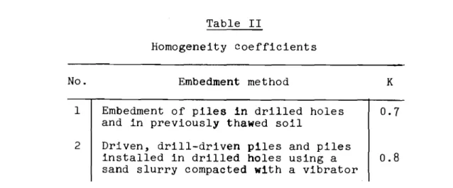
Table II
Homogeneity coefficients
No. Embedment method K
1 Embedment of piles in drilled holes 0.7
and in previously thawed soil
2 Driven, drill-driven piles and piles
installed in drilled holes using a 0.8
sand slurry compacted with a vibrator
24. The strength of a thawed foundation soil is considered only for
drill-driven piles in non-heaving soils.
The design strength of the foundation soi] of a pile in this case is
de-termined by formula (3):
The standard characteristics of permafrost are taken from Tables III 1,1];
u l 25. and IV.
k, m, u, sセL Ii' F, pH - same values as in formula (2);
fH - the standard strength of soil along the lateral surface of a pile
in the active layer taken from Table II in SNiP II-B, 5-62;
- the length of the pile in thawed ground equal to the design depth to the permafrost table (excluding soil fill);
- mean perimeter of pile in active layer.
Explanatory notes:
1. The values shown in the tables correspond to limiting long-term
strengths. They can be corrected on the basis of long-term construction
expe-rience and tests, including static pile tests.
2. For intermediate temperatures, the values for SH and pH are determined
by linear interpolation.
3.
It is forbidden to use the values of SH and pH shown in Tables IIIand IV in saline soils with a concentration of salt (NaCl, CaC12 ) greater than
0.1%.
4.
In the design of driven and drill-driven piles the values of SH, shownof layers and lenses exceeding 2 centimetres in thickness and occupying more than 50% of the total thickness of the layer.
5.
If the pile rests directly on ice, the strength of its lower end セウnot considered.
Table III
Standard shear strength of frozen soil SH in tons/m2
°c
-0.5 -1. 0 -1. 5 -2.0 -2.5 -3.0 -3.5 MセNoand lower H
S 5.0 10.0 12.5 15.0 17.5 20.0 22.5 25.0
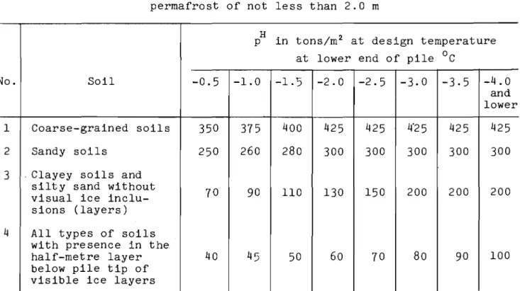
Table IV
Standard strength of soils in the plan of lower ends
H
of piles (p ) at design depth of pile embedment in permafrost of not less than 2.0 m
H
in tons/m2 at design temperature
p
at lower end of pile
°c
No. Soil -0.5 -1.0 -1.5 -2.0 -2.5 -3.0 -3.5 -4.0
and lower
1 Coarse-grained soils 350 375 400 425 425 4"25 425 425
2 Sandy soils 250 260 280 300 300 300 300 300
3 . Clayey soils and
silty sand without
70 90 110 130 150 200 200 200
visual ice inclu-sions (layers)
4 All types of soils
with presence in the
half-metre layer 40 45 50 60 70 80 90 100
below pile tip of visible ice layers
26. On developed construction sites where long-term geothermal data are
available, the design temperature at various depths in the zone of pile em-bedment in permafrost and the design temperature at the lower end of the pile are determined from temperature observations.
The temperature in each layer is found as the average of several measure-ments made at this depth in at least two holes during the period of deepest thawing in the active layer.
27. In the absence of long-term temperature observations at the
construc-tion site, the design temperature of the soils at various depths can be de-termined approximately by formula (4) for rough calculations at the design stage, in relation to the ground temperature at the depth of zero annual ampli-tude:
(4 )
the design temperature in the zone of セュ「・、ᆳ
°
constant and equal to -0.5
c.
t
h - temperature at the base of a frozen-in pile;
to - temperature at the depth of zero annual amplitude;
hi - depth from the design permafrost table to the depth where the design
temperature is determined but not greater than
6 - 7
m.Formula (4) should be used with temperatures at the depth of zero annual
°
amplitude of -2 C and lower. With temperatures above _2°C, ment of the pile is assumed to be Explanatory note:
In the absence of long-term observations, the ground temperature measured in a borehole at a depth of 15 m may be taken as the temperature at the depth of zero annual amplitude.
28. The design position of the permafrost table, which determines the
em-bedment depth of the pile, is established in the autumn on the basis of tem-perature measurements in foundation soils of occupied bUildings which are sim-ilar to those under construction.
In the absence of observation data, the design position of the permafrost table of the merging type (i.e. reached by the active layer) can be assumed equal to the design thickness of the active layer, which is determined from
formula (5):
H'
='"t
H"(5)
HP - design thickness of the active layer in metres;
H
H - standard thickness of the active layer determined according to
SN 91-60;
mt - the coefficient accounting for the decrease of the active layer
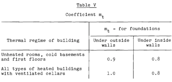
dur-ing occupation of the builddur-ing in relation to the temperature regime on the first floor and design of the basement, taken from Table V.
Table V Coefficient m
t m
t - for foundations
Thermal regime of building
Unheated rooms, cold basements and first floors
All types of heated buildings with ventilated cellars
Explanatory note: Under outside walls
0.9
1.0 Under inside walls0.8
0.8
With the laying of a thermal insulating cover on the soil in the basement and also ducts for artificial or natural ventilation of the basement, the de-termination of the design thickness of the active layer is carried out by ther-motechnical calculations.
29. The design thickness of the active layer may be measured from the top
of the fill, if the fill was placed during the engineering preparation of the site, well ahead of actual construction.
30. In heavy construction and the erection of important structures, the
design strength of the foundation soils determined from formula (2) or
(3)
iscorrected as a result of testing piles under static load during construction under supervision by the design organization according to recommendations in Appendix 12 of these standards.
31. The design strength of foundation soils of the pile - P from testing
results is determined by formula (6):
R
P
=
0.7 P (6)H
P - standard strength of foundation soils assumed equal to the average
of three values of the limiting strength of soils determined in
tests under similar エ・ュー・イ。エオイセMウッゥャ conditions.
The limiting strength of foundation soils under axial loading is deter-mined by the load, which results in a non-attenuating shifting of the pile at a rate of 0.5 rom per day or slightly higher.
Explanatory notes:
1. If the pile during the test is not brought up to the limiting
con-dition, then the load in which the test can be discontinued must be not less
2. The design strength of the f'oundar.Lon soil s ;mbj ected to horizontal forces is found from a curve illustratin, the shift of the top of the pile versus load in static tests.
3.
The design strength of foundation soils must not exceed the designforce which the pile can withstand based on its strength and resistance to cracking.
32. The design strength of foundation soils which tend to pullout the
pile P
E is determined without considering the strength of the soil in the
active layer using formula
(7):
P = xm uES· I
• i i
where k, u, S., 1. have the same values as in formula (2);
1 1
m - coefficient of working conditions; for piles embedded in permafrost to a depth of up to 2.0 m it is assumed to be 0.9, and 1.0 at greater depths.
The standard shear strengths of frozen soil in formula
(7)
are assumedfor the design temperature regime of foundation soils determined in accordance with sections 26 or 27 of the present standards.
The design strength of foundation soil, determined from formula
(7),
mustbe pinpointed by special pUll-out tests as outlined in section 30.
When determining the design strength of foundation soils tending to pull
out the pile, it is necessary to consider the requirement of section 31 and
the recommendations for tests on experimental piles (See Appendix 12.).
33.
Checking of single piles with respect to the second limiting condition(section 20) is carried out by testing the pile under a static load. The
set-tlement of the pile under standard loading must not exceed the limiting de-formation given in the design, taking into account the possibility of differ-ential settlement.
34.
The sequence for calculating loads and combination of loads acting onpile foundations is described in Chapter 11-62 of SNiP ll-A and also in the
design standards for various buildings and structures. The following additional
considerations also apply:
(a) temporary loads (wind, snow, etc.) are assumed equal to their maximum values observed over a number of years (at least 10) in the autumn (when the active layer is thickest);
(b) short-term loads are assumed without considering the dynamic coefficient and are reduced by 50% for effective loads of cranes and by 25% for mobile
Explanatory note:
The loads are not reduced when the piles are designed for strength and regarded as structural elements.
35. The design load on piles pP in formula (1), when the piles are
ar-ranged in rows, is determined as the sum of the reactions of the neighbouring spans in the load transfer structure, disregarding its rigidity.
In a random distribution of piles joined by a rigid load transfer struc-ture, the design load on a pile is determined by formula (8):
p N P =
--+
n -M,x±
-Ex. 2 I( 8 )
N, M , M - the normal compressive strength in tons and the design momentsx
y
in TM (ton-metres) relative to the main axes in the plane of the bottom of the pile foundation;
n - number of piles in the foundation;
xi' Yi - distance in metres from the main axes in the plan of the pile foundation to the axis of each pile;
x and y - distance in metres from the main axes in the plan of the pile foundation to the axis of the pile for which the load is being calculated.
36. The smallest amount of pile embedment in permafrost is assumed to be
2 metres, to ensure safety and durability of the building or structure.
37. If piles are placed in permafrost close to service conduits, the depth
of embedment, which has been calculated or determined as outlined in section 3b, must be increased to take possible local thawing of the permafrost into ac-count.
The zone of thermal influence of service lines in ventilated conduits is assumed to extend 2 metres from the outer walls of the conduits; for other cases it must be determined by heat engineering methods.
38. In the presence of an active layer consisting of 」セ。ケ soils, the re£
sistance of piles to heaving must be checked by formula (9):
II H
n ue - n N セ P.
I 2 - B
(9)
H
N - standard vertical load on a single pile from the action of constant
forces only, in tons; P
B - design resistance of the pile to pUll-out determined from formula (7);
TH _ standard relative heaving force in tons per linear metre of
the pile perimeter, assumed in the absence of test セセエ。 to
be 9 tons/m for an active layer of up to 1.0 metres in エィゥセォᆳ
ness, and 15 tons/m, if the active layer is thicker;
n1 and n2 - coefficients of overloading assumed equal to n1 = 1.1 and
n2 =
0.9.
Explanatory notes:
1. In the presence of the pull-out force
NF,
its value is substitutedinto the formula with a minus sign. The coefficient n2 is assumed in this
case to be equal to 1.1.
2. The stability of the piles must be verified also during the
construc-tion stage; in this case NH is assumed equal to the actual weight of the
un-finished building in the fall-winter period. If the condition of formula (9)
is not fulfilled in this test, it is necessary to protect the soil in the active layer from freezing.
39. For piles placed in drilled holes and thawed soil, use may be made of
square shapes as well as cross-sections with a developed perimeter. The area
of cross-section depends on the maximum utilization of the material of the
pile .(pipe pile,
H
pile, etc.). Piles with a complex cross-section areac-cepted on the basis of engineering and economic considerations. Piles embedded
in drilled holes are placed without being pointed and, in the case of a mono-lithic load transfer structure, the piles are reinforced to provide stable con-nections with the latter.
In the case of pipe piles, the portion embedded in permafrost is filled with sand; in the active layer the pipe is filled with mark 100 concrete.
40. Under the bearing walls of buildings a single row of piles should be
provided in the design; the axis of the row of piles is arranged as a rule along the axis of the wall of the first floor.
In the case of large off-centre loads, the axis of the row of piles is
best placed to decrease the eccentricity of the vertical forces. The placing
of piles under the corners of brick walls and at the intersections of the axes
of bearing walls of panel buildings is compulsory. It is not recommended to
place piles under window and door opertings.
41. Where piles are placed in clusters, the minimum distance between piles
embedded in drilled holes must be 0.5 metre. In other methods of embedment,
the minimum distance between the pile centres at the depth of the lower ends is assumed equal to 3d, where d is the diameter or the side of the pile.
The arrangement of piles in the plan of this foundation is such that the resultant of constant forces which act on the pile foundation is transmitted close to its centre of gravity at the depth of the lower end of the piles.
42. In the installation of piles, the requirements in section 21 must be
satisfied; underloading of individual piles must not exceed 20%.
43.
Where the active layer consists of clay soils, the load transferstruc-ture must be elevated above the ground surface to the height of soil heaving observed in the given region.
44. Reinforced concrete load transfer structures (beams, slabs) are
de-signed according to present design standards of reinforced concrete units. In
the case of a row of piles under walls of buildings, the load transfer
struc-ture is designed as a fastening beam bearing on the pile. The minimum width
of load transfer structure is designated as 40 cm.
Determination of the height of the load transfer structure and the
cross-section of reinforcement is carried out by calculation. The smallest height
of the load transfer structure must be such as to enable the concrete cross-section to withstand the transverse force without installing curved reinforce-ments, but must be at least 0.3 metre.
Explanatory note:
When laying brick walls in winter, the strength of the load transfer struc-ture is checked by considering the load from the weight of the thawed material.
45.
In a monolithic load transfer structure it is not recommended to leavegaps. Where joints are unavoidable, they must coincide with temperature joints
in the walls.
46.
The top of the load transfer structure is best placed at the level ofthe floor of the ventilated crawl space; the floor slabs are placed directly on the load transfer structure.
An example of a pile foundation design is given in Appendix 2.
47.
Where there is a considerable slope to the ground surface, or wherethe height of the ventilated crawl space varies, the installation of the load transfer structures at various levels is permitted.
48.
On the blueprints, the axes of the rows of piles must be joined to theaxes of the walls and marked. The piles in the plan must be numbered along the
IV. INSTALLATION OF PILE FOUNDATIONS
49.
The following methods of installing frozen-in piles are regulated byinstructions given in this part:
(a) installation of piles in drilled holes;
(b) installation of piles in soil which was thawed prior to construction; (c) driving of piles into holes of smaller diameter or into frozen ground with a temperature close to thawing.
50. The engineering preparation of the area must precede the installation
of piles.
Freezing of taliks (thawed zones) and areas with soils close to thawing
discovered on installing the piles is carried out as a special project. The
design organization must be informed of these measures in good time.
51. Reinforced concrete piles are manufactured with close adherence to all
reqUirements in TU 120-55 and engineering instructions for the preparation of
the piles. Greasing of the pile linings is done with clay or lime paste; use
of oil emulsions are prohibited.
The piles are brought to the construction site when concrete has reached 100 per cent design strength.
Explanatory note:
The preparation of piles equipped with pipes for temperature measurement
is carried out in conjunction with the design specifications. The number of
such piles under the bUilding varies from four to six.
52. Deviations from the specified position of piles embedded by any method
must not exceed the values given in Table VI.
Piles Installed in Drilled Holes
53.
Holes are drilled with percussion and rotary drills adapted for boringfrozen soils. The technical characteristics of the most common machines for
boring holes are given in Appendices
3
and4.
54.
The drill rigs are placed above the top of the hole and the drillingis carried out as follows:
(a) the base of the rig must be placed horizontally, which is done by level-ling the drillevel-ling site;
(b) the axis of the drill must coincide with the design axis of the hole. An example of work organization in the construction pile foundations is
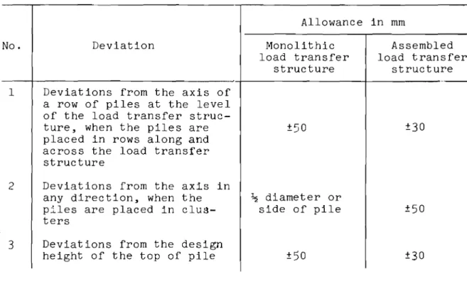
Table VI
Permissible deviation of piles from specified position
Allowance in mm
No.
1 2 3 DeviationDeviations from the axis of a row of piles at the level of the load transfer struc-ture, when the piles are placed in rows along and across the load transfer structure
Deviations from the axis in any direction, when the piles are placed in clus-ters
Deviations from the design height of the top of pile
Monolithic load transfer structure ±50 セ diameter or side of pile ±)o Assembled load transfer structure ±30 ±50 ±30 Explanatory note:
When the piles are placed in rows, ultimate deviations in one direction are permitted for not more than four adjacent piles.
55. The diameter of the hole must be 5 centimetres greater than the largest
diameter of the pile.
56.
It is recommended to case the holes throughout the layer of thawedsoil.
57.
In the case of a monolithic load transfer structure, the holedimen-sions must not deviate from specified dimendimen-sions by values exceeding those in Table VII.
Table VII
Permissible deviations in drilled holes
No.
1
2
3
Deviation
Misalignment of hole axis with pile axis at base of load transfer struc-ture along and across row of piles
Deviation from design depth of hole
(a) overdrilling
(b) drilling to insufficient depth Deviation from hole diameter in zone of pile embedment
Allowance in rom
±50
not standardized 50
Explanatory notes:
1. For prefabricated reinforced concrete load transfer ウエイオ」エオセセウL
in-sufficient depth of drilling of not more than 30 millimetres is allowed.
2. Deviations from design dimensions and other data are entered in the
log on boreholes and pile installation (Appendix
6).
58.
The installation of a pile into a drilled hole is carried out in thesummer not more than three hours after completion of the drilling, and in
win-ter, not more than three days after completion of the drilling. Prior to pile
embedment the hole must be protected with a removable cover.
59.
The hole may be filled with solution at the time of embedment orafter-wards. In the first case the pile must be placed in the hole immediately after
it is filled with solution. The recommended solutions are given in Table VIII.
In the second case, sand slurry only is used; the slurry must be vibrated
during placement. It is essential to e n s nr-e that the space between the pile
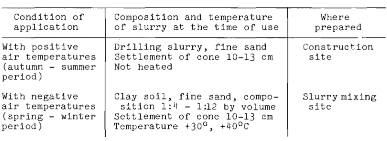
and the walls of the hole is completely filled with slurry. Table VIIl
Recommended slurry compositions Condition of application With posit i ve air temperatures (autumn - summer period) With negative air temperatures (spring - winter period) Explanatory note:
Composition and temperature of slurry at the time of use Drilling slurry, fine sand Settlement of cone 10-13 cm Not heated
Clay soil, fine sand, compo-sition 1:4 - 1;12 by volume Settlement of cone 10-13 cm Temperature +30°, +400
c
Where prepared Construction site Slurry mixing siteThe quality of slurry is controlled by the construction laboratory and is
shown in the log of the physico-mechanical properties of slurry (Appendix
7).
Temperature measurements of the slurry prior to pile placement are taken by the foreman.
60. It is recommended that the slurry be transported by truck, after which
it is discharged into a measuring bin and moved into the drill hole. The
quan-tity of slurry used must be such as to fill completely the space between the piles and the walls of the hole, with allowances for overdrilling and possible enlargement of the drill hole.
61.
Prior to placement, the pile must be protected from snow and ice andvisually examined. Any water in the hole must be pumped out. The placing of
a pile into a hole is carried out by a jib crane or a tower crane. The
embed-ment of a pile takes place usually under its own weight.
Piles Embedded in Ground Thawed Prior to Construction
62. The thawing of the ground at the site of the installation or driving
of piles can be accomplished with steam, water, electric current, etc.
The requirements given below apply to セィ。キゥョァ by steam points and placing
the piles in the ground which has been waterlogged during steam thawing.
63.
To thaw the ground with steam, the following equipment and materialsare necessary:
(a) steam boiler - recommended types of boilers and their characteristics
are given in Appendix
8;
(b) network of steamllnes; (c) steam points;
(d) distributing manifold with flexible hoses for carrying steam to the points;
(e)
inventory trestles - crane carriages for placing points and suppurtingthem in a vertical position during embedment.
6
LI . The steam boiler should be placed along the axis of the building beingconstructed. A temporary structure is set up to accommodate the boiler. The
boiler may be left in the open only in the summer or in the fall.
65.
Main and distributing steamlines must be placed on low trestles orwood blocks sloping toward the boiler. For convenience of assembly, the
dis-tributing steamlines must consist of separate sections and be joined to the
main steamline by means of a valve. Plugs are placed on the main steamline at
the connections with the distribution lines. It is essential to insulate all
steamlines.
The steamlines must be kept in good working order. The escape of steam
and the discharge of condensate on the building site must be prevented.
66.
The distribution manifold must have the same diameter as thedistri-bution steamlines; outlets for switching on the steam points are welded to it. Valves are fixed onto the outlets of the distribution manifold.
A monometer for registering steam pressure in the steam points is placed
in front of the distribution manifold. The steam points are joined to the
dis-tribution manifold by flexible high pressure hoses. The steam points and their
b)
Fig. 1
Construction of steam point
1 - end cap, 2 - handle,
3 -
tMセッゥョエ4 -
flexible hose,5 -
cap,6 -
holein frozen ground,
7 -
thawed ground,8 - permafrost; (a) ordinary point,
(b) ripper point
67.
To fix the correct position of' steam points, it is recommended toexcavate holes or use gauges at the pile locations. If it is established by
drilling that it will be impossible to penetrate the surface layer of fill with steam points, a trench must be excavated to the entire depth of the fill.
68.
The thawing of frozen ground at the pile locations is carried out byone or several steam points working simultaneously. The optimum number of
points must be selected by trial and error in relation to the type of ground, temperature and cross-section of the pile.
In determining the number of' holes to be steamed simultaneously, the de-cision must stem from the fact that one steam point must have four to five square metres of heating surface of the boiler.
69.
To ensure that the steam points penetrate vertically into the ground,wood or metal trestle-type scaffolding is used; a diagram of the scaffolding
View along 1-1 steam .._yoints
セMMゥ
J.-Z£+ View along 2-2 @(!) Fig. 2Scaffolding for mounting steam points 1 - trestle, 2 - platform for steam points,
3 -
steam points,4 -
flexible hoses,5 - distribution manifold, 6 - valves,
7 -
distribution steamlines,8 -
frozenground,
9 -
thawed ground70. The process of thawing frozen ground is regulated by steam pressure,
the length of time that the steam points are in the ground, and the amount of steam that goes through the points.
To obtain the optimum size of talik corresponding to the cross-section of the pile, it is recommended that:
(a) The steam pressure at the distribution manifold, for each steam point
(with other points closed) is set at
3 - 4
atmospheres for clay soils withoutcoarse fragmentary material;
4 - 6
atmospheres for sandy soils;6 - 8
atmos-pheres for sandy soils with gravel and stones up to 10% by volume.
(b) The length of time one steam point (or group of points) is left at one
location is assumed to be up to 10 minutes in clay ウッゥャセ and 15 - 20 minutes
in sandy soils; the penetration of steam points, after their exposure at one level, is by rotating them with the help of a handle until they reach frozen ground again.
(c) At the initial moment of thawing the soil, the output of steam is set
at the minimum. As the points penetrate deeper into the ground, the steam
will stop coming to the surface and at this point the steam output is gradually increased to the maximum for a given pressure.
(d) In clay soils it is possible to use the following methods: the steam
point is quickly lowered to the design depth and the thawing of soil occurs during withdrawal of the steam point from the ground in 0.5 metre intervals.
71. The diameter of the thawed zone js set at 10 - 25 em greater than the cross-section area of the pile.
72. In soils with mixtures of stones or small boulders, steaming is
car-ried out 0.5 - 1.0 metre below the design depth and the steam point is held
at this depth for 20 - 30 minutes.
Explanatory note:
When working in such soils, it is expedient to supply the steam point with a sharp cap for loosening the ground, or a cap combined with a chisel.
73.
The embedment of piles in previously thawed soils is carried out notmore than one day after completion of steam thawing in winter and spring, 2
days - in summer, and
4
days - in autumn.74.
For the embedment of piles, jib or tower cranes are used. Theinstal-lation of piles is carried out with the aid of a sling with a spring hook. The spring prevents the hook from slipping off a collar fitted onto the pile. For embedment in thawed soil, the pile is dropped abruptly from a height of
2 - 3 metres. In the event of the pile being pinched in the ground, it is
necessary to raise it again and drop it abruptly several times to the depth of embedment at the design level or drive it in.
75.
If the pile does not go down to the design depth because of thefor-mation of a plug of coarse material at the bottom of the hole, it is necessary
to carry out additional thawing of the soil as outlined in section 72, in order to move the coarse material into the thawed ground below the end of the pile.
76.
If the piles are installed in the fall, measures must be taken toprevent the piles from heaving during freezing of the active layer; for example, by providing temporary thermal insulation around the piles.
77. Where pile foundations are installed in sandy soils, the embedment
of the piles can be carried out simUltaneously with the thawing of the ground. The pile, together with the steam points securely attached to it, is placed
in the hole. The vertical orientation of the pile is ensured by a pile driver
or guides suspended from a crane-type excavator. A diagram for carrying out
this work is given in Figure
3.
The pile sinks under its own weight as the soil thaws beneath its end. If the sinking of the pile is insufficient, use may be made of a pile driver or vibrator.
78.
The steam thawing of the soil should be started on the higher partsFig.
3
Installation of pile while ground is being thawed
1 - excavator, 2 - boom,
3 -
suspended directionguide,
4 -
flexible hoses,5 -
steam points,6 - pile, 7 - collar for holding points to pile,
8 -
thawed ground,9 -
frozen groundIt is essential to maintain continuity of the entire operation which is achieved as follows:
(a) the site is divided into individual sections along the length of ing or structure; the number of sections depends on the length of the build-ings;
(b) thawing is started in the first section;
(c) while the soil is being thawed in the second section, piles are in-stalled in the first section.
79.
Safety regulations in steam thawing operations are worked out andmaintained by the construction organization in relation to the method of pen-etration used, available equipment and other local peculiarities.
In other methods of pile foundation construction use should be made of
safety regulations for the corresponding types of work under normal セPョ、ゥエゥッョウN
80.
The contractor must keep a record of all operations involving steamthawing of soil and installation of piles as shown in Appendix
9.
Drill-driven and Driven Piles
81. The drilling of holes or thawing of ground for installing
drill-driven piles is carried out as outlined in sections
53, 54, 68
and70
of thiscode.
82. The diameter of the hole for drill-driven piles is determined
exper-imentally. Initially, the diameter of the hole or thawed zone is set at
50
romsmaller than the diameter of the pile. The depth of the hole must not exceed
the depth of embedment of the pile less the length of its tip.
83.
The pile driving is carried out according to existing norms andin-structions for work in unfrozen soils.
84.
If test driving does not succeed in embedding the pile to the designdepth, drill-driven piles should be used.
85.
It is expedient to use a large hammer for driving piles in frozensoils with the weight of the hammer being 1.5 times the weight of the pile.
86.
The contractor (the ウオー・セゥョエ・ョ、・ョエI must keep a record of pile drivingoperations (Appendix 10).
Construction of Load Transfer structures
87.
In concreting and assembly of load transfer structures it is essentialto follow "Provisional Instructions for Construction-Assembly Work in the Far
North and Permafrost Regions (VU
2-60)".
88.
The construction of-a load transfer structure is allowed only afterthe installallation and acceptance of the piles and not before ground temper-ature observations have ascertained complete adfreezing of the soil to the
o
piles (mean temperatures below
-0.5
C) within permafrost.V. ACCEPTANCE OF PILE FOUNDATIONS
89.
The acceptance of pile foundations is done by a commission consistingof representatives of the contractor and the client, who check whether the in-stalled pile foundation corresponds to the design and requirements of this code.
90.
The construction organization presents the following records to the commission:(a) factory ratings of reinforced concrete elements (piles. reinforced concrete beams)j
(b) the plan of the pile cluster. indicating any deviations of piles from specified positions and double piles (if present)j
(c) general report of installed (driven) piles (Appendix 11);
(d) work log (depending on the method used. see Appendices
6. 9
or 10);(e) certificate of acceptance of reinforcements. records of concrete work.
records showing the selection and testing of control samples. and records of electrical and steam heating of concrete (in the case of continuous load trans-fer. structure and floor)j
(f) geodesic layout of pile cluster.
91. The builder (permafrost station) submits to the commission processed
temperature data (logs and graphs) sufficient for an understanding of the temperature regime of the soils at the piles and on the construction site.
92. On the basis of the acceptance of pile foundations by the commission.
two documents are prepared:
(a) a certificate of acceptance of the pile foundationj
(b) a certificate of examination of permafrost conditions at the piles during the installation of the foundation.
93.
Permission to continue construction of the building and loading ofthe pile foundations is given by the commission on the basis of the estimate of the design strength of the pile. keeping in mind the observed temperature regime of the ground at the pile.
If the temperature regime at the pile differs essentially from the design. the commission notes in the document the thermal technical measures and estab-lishes the possibility of continuing construction with allowances for gradual storey-by-storey loading of the foundation in relation to the re-establishment of the permafrost regime.
The control of recommended heat engineering measures based on these rec-ommendations and an estimate of their effectiveness at various stages of com-pletion are carried out by the permafrost station.
94.
The structure is handed over to the client only after the temperatureAPPENDIX 1
AN EXAMPLE OF DETERMINING THE DESIGN STRENGTH OF THE FOUNDATION SOIL OF A PILE FOR CONDITIONS AT NORIL'SK
A prismatic,
8.0
metre long, reinforced concrete pile with a cross-sectionof
32
x32
cm is installed in a drilled hole. The soils are: to a depth of0.5
metres - coarsely fragmented soil (fill) placed in advance;0.5 - 5.0
metres - sandy soil;
5.0 - 10.0
metres - clay loam with ice layers of variousform and orientation.
The design thickness of the active layer based on the results of long-term geothermal observations at a test site, with allowances for the thermal
influence of bUildings, is assumed equal to: for clay soils -
1.8
metres, forsandy soils -
2.0
metres, for coarse, fragmented soils -2.5
metres.The design temperatures in the zone of embedment of the pile in permafrost
were determined from observations in three holes. Mean monthly ground
temper-atures are given in the table for a period in October, when the depth of thaw was at its maximum.
Depth in m
2
3
4
5
6
7
Temp. in
°c
-0.5
-1.7
-2.8
-3.7
-4.4
-4.8
The design strength of foundation soil is determined from formula (2):
P=km (uES; Ii
-+
Fp"The values of factors in the formula are: m
=
1.0;
k=
0.7
(Table II);u
=
4 x 0.32
=
1.28 m; F
=
0.32 x 0.32
=
0.1 m
2•
To determine SH and pH, we find the design temperatures for individual
layers. Let us assume a division into layers of up to 2 metres in thickness.
The design temperatures for the various layers are:
05
'+
_2.d I j。セイ tp= - .
0 _ _ 1.6SoC I 2 we assume that 1I1a,ye:'t= -
2,8+
-4.4 p, 2 we assume that 11Ilayer t _ -4.4+ -4.8 I) - 2 we assume thatt
p =- -l,r'C; IThe design temperature at the lower end of pile is assumed to be
Standard strengths SH and pH for the design temperatures are taken from Tables III and IV
sセ
=
13.5 tons/m2,sセ
=
23 tons/m2,sセ
=
25 tons/m2, pH
=
100 tons/m2• ES· II = 13J5X2+
2;J.uX;t+
25,OXI "'" 98Substituting the obtained values into formula
(1),
we ッ「エ。ゥョセP=O.7XI 1l.28x98+0.IXIOO) - 94.8tons.
For approximate calculations, the design temperature can be taken as the arithmatic mean of temperatures observed at various depths in the zone of pile embedment.
t = (0.5+1,7+2,8+3.7+4.4+4.8) __ 2.98"C,
p 6
Let us assume that t
=
-3.00C, SH=
20 tons/m2• In this case the design pstrength of the foundation soil is equal to
P - O,7XI,O (1,28X20X5+0.lXIOO) - 96.6 tons. APPENDIX 2
AN EXAMPLE OF A DESIGN OF A PILE FOUNDATION
APPENDIX 3
TECHNICAL CHARACTERISTICS OF PERCUSSION POWER DRILL
Specifications
Diameter of drill, in mm Weight of drill, in kg
Height of hoist above drive, in mm
Number of blows per minute Rate of movement, in km/hr Specific pressure on
ground, kg/cm2
Electric motor (type) Revolutions of drum per
minute
Power, in kilowatts Composition of crew
(Noril'sk experience), men Output of machine (standards
for Noril'sk combine)**
"Uralets" "Uralets" BU 20-2M BU-2 BS-2 300 300* 400* 850-1300 1700 1200 450-1000 500-760 520-700 52-54 48-52 50-52 0.9 0.9 0.9 0.58 0.7
MA-203-2/6 MA-204-2/6 A-72-6
975 930 960 20 32 20 2· 2 2 Running m/hr in soils III category IV category V category
Cost of drilling in rubles per linear metre in soils:
III category IV category V category (Estimates of Noril'sk combine) 1.5 0.7 0.3 3.20 5.20 10.21 1.20 0.55 0.25 6.33 11.28
*
The machines work in Noril'sk with reconditioned factory bits, 350 and400 mm in diameter. Hence standards and estimates are given for holes
350 and 400 mm in diameter.
**
IV category: thawed gravelly-stony soils, very dense clays, slates andmarls; frozen soils - clay loam, sandy loam; V category: frozen
APPENDIX
4
TECHNICAL CHARACTERISTICS OF ROTARY POWER DRILLS
Specifications
Diameter of drill, in rom
Depth of drill, in m
Operation of drill
Carrier
Man production
Output in m/hr in frozen clays
and sands (IV category)
BTS-2
Up to 350
Up to 30
Mechanical
Tractor S-80
Yes
3 - 4
ShAK-2
250
Up to 40
Mechanical
Tractor S-80
No
APPENDIX
5
PILE INSTALLATION IN DRILLED HOLES
I - pins for fixing holes; 2 - percussion drills;
3 -
drilled holes;
4 -
piles installed in drilled
holes; 5 - crane route; 6 - outline of area covered
by boom of tower crane;
7 -
storage area; 8 -
APPENDIX
6
Name of construction organization Drill Type
&
sizeBits
Proj e c t "-- _ セイ。ョ・ for embedding piles
Type and dimensions of piles
Temperature of frozen ground _
WORK LOG
For drilling holes and installing piles
s e
Date
No. fDnlling
Depth of Depth ofof of of holes holes, m pile em- Foreman'
No. kirill holes tart
.F:ll1llh
bedment,Remarks signatur
ing planon ィッオイセィッオイウ セウゥァョ。」エオ。 m
Gセャセ
1 2 3
I
4 5 6I
7 10 \IAPPENDIX 1
Name of construction organization __
LOG
Physico-mechanical properties of clay-sand slurry
c
onstruc-I
Unitイゥウエオイ・セpャ。ウエゥcMGt・ュー・イM
tion Date Fractions weight ontent ゥエセ atufe
project -:>0.1 <0.1 iZZャヲセ sat e- 0 Signature
loiN loiN gm/cm
3
in % .
」セI
slurry1 2 3
APPENDIX 8
Technical characteristics of steaming arrangement for pile installation
セ
Vertical boilers PortableShS-2
/ShS-'
VTKB P-38 P- 1I
P-75Specifications 0.5·8
Steam output, kg/hr 400-455 1000 400-500
I
250 270 850l'1aximum pressure, atm 8 8 8 15 12 12
Heating surface, m2 15,7-16.2 27-38 13.7-14.5 10.15 10.8 21
Length}
-
-
-
4050 3890 4380 Width in mm ..,....-
-
1560 1770 1990 Height 3000 3689- 4165 2530 2880 3150 3633 Outside diameter, mm 1156 1544- 1424-
-
-1450 Weight, kg 2080-2300 4190 3910 3600 5350 7500 APPENDI.X 9Name of construction organization
Project - - - - _
Type of boiler, heating surface, m2
WORK LOG
For thawing ground and installing piles Crane for installing piles
Type and dimensions of
piles---13 G-f o OJ s:: H CI1 :::1 5 +> IV ell H s:: 0 bOG..-i .r-! U)
,
!ll s:: >, OJ+> Time of Height I
-H 0 5 r-l 5
セoj
セイッオョ、セヲ。ゥセ・、
<IYOrt.l セNNMiK^ 5'0 rt.l CI1 OJ s:: 51V5
GJ l1) +> CI1 CI1 OJ :::1 OJ rt.l0S:: ィ。セゥョァ r-lO CI1;3::u r-l to :::1 OJ rt.l 0 +> CI10D n rs ..-1.,-; セdNゥャNl ..-Iell 'r-!0.(\1 Hori'Os::: OJ.o ., +>:::1OJ rt.l+> 0.rt.l s:: ..c:: 6ll o.+> 'O..c::s::
s:: s..c::+> s:: ell +>..-1 r l o.Hr-l rt.l CI1 G..-i..-l G-fCl1bOo. ..-I G..-ir-l
IOJ rt.l
G..-io.0 SlIJG-f.po G..-i+>+>/oo o OJ:::1 OJ0S::r-l 0. s:: Or-l s:: r-l bG-< .. セ
+>0'0 s:: CI1 eo ell CI100J H
OJ s::: (Ij..-I.r-!
I
..-1:::1 OJ OJrt.lH ..-I OJ+> ..-I :::1 H s:: CI1.j..Y ' 0 Q)'t:1S:: '05,0. 5 .c eo '0 +>rt.l rt.l +> OJHO 5 CI1 0 .pQCI1 00...-1,>, .r-!G-..!+> OJ s:: ell s:: OJ U :>OJN OJ
o
:z:
Cf) Ez
rt.l 18 80 co W O'r-! 0 « «+> 0::- - -
3I
4 1-5-- -
--
-11-'I 2 I' 6 7 8 8a 9 10 12
Steam pressure atrn
I
Explanatory note: Log is filled out on each shift. The reasons for
not reaching the specified depth of embedment and the duration of
APPENDIX lO Name of construction organization
Project (structure)
-LOG
For installing driven and drill-driven piles Pile driver
-Type of hammer
-Weight of percussion part of hammer __
Energy of blow of diesel-hammer (rated)
-Stearn (air) pressure in cylinder
-Material of pile _
Permafrost conditions
-Diameter of first hole
-Method of advancing holes
-Pile no.
-No. of pile as manufactured
-Length of pile, m _
Cross-section of pile, cm _
Surface elevation at pile _
Depth of lower end of pile (design)
-(actual)
---Duration of operation of hammer, minutes
-Stearn (air) pressure (manometer reading) _
Number Depth of
Height of lift of No. of of blows
No. percussion part of ground in the pile em- Refusal,
hammer, in cm section ground bedment, in cm Remarks
section in cm
APPENDIX 11 Name of construction organization
Proj ect _
Composite record of installed piles
No. of' pepth of Absolute I:eviatim Refusal, G-i
pile 6
..
o. U)
..
G-i embeq- eleva- 0 of in cm oU) ...Q)'d0
セ
P1ent, Jl1 tions'0 Q) m 6 .. piles, Fordr:ll.en 'driQ)
Q) ri s.:::", CIl o.p
&
drill O·rl U)H ·rl o 6 .p H.r: in cm driven .c 0.セ
s.::: セ 0.6 ·rl U) G-ibO .p
CIl .p 0 .ps.::: s.:::s.:::
.,.,
piles Q) bO.pri 0 1Gos.::: 0"" ·rl 0 s.:::Q)
-_
.._ -
6 s.::: s.::: 0. CIl Q).,.,
... .,.,Q) Q) 0. o.r: 1 I ri6 G-i セ ·rl U) Q) G-i.p 0.,.,
.,.,
po -r+-lbOQ) s.::: lri Ocll s.::: ri 'dCll .p .ps.::: U)
.,.,
'dells.::: セ」iャBBU) ri 0..c cIl U)"" ri bO cIl s.:::G-i CIlbO bOU) U) U) HbO 'Os.:::.,., H.p セ
I
セ
s.:::s
U) s.:::Q)eo
oU) 0. Q).pI
.,.,
U) .pセ セ o セH riQ) ·rl.,.,poU) s.:::·rl O·rl 'Os.::: CIlOpo CIlU)o' H cIl Q) o >< H><.,.,
.r+rl 6 c Q)_ . - 2 . - - : L L (.) Q Q -S....-0 セセH U) ·rl Q.3;LQ)Q) riCllS-..:.. $..-o cIl セs.::: D...D.Q.:>H
&
·rlI 2 3 セ MUMiセエゥMiMWMNM 8 9 I 10 II 12 13 14 15. 16
I
I
I
I
N Signature : _ APPENDIX 12RECOMMENDATIONS FOR TESTING PILES UNDER STATIC LOADS
1. The necessity of carrying out static tests on experimental piles,
their number and design, is established by the planning organization in rela-tion to the available experience, purpose of construcrela-tion and working con-ditions.
The tests are carried out by the planning organization with the partici-pation of the permafrost station or research organization where necessary.
The cost of static tests is included by the planning organization in the construction estimates.
2. The equipment for testing the piles is specified in the plan. The
recommended installation for testing piles in axial compressive loading is
given in Figure
4.
Figure5
shows the reference installation.3.
The ultimate strength of foundation soils of the pile is determinedwhen the ground temperature reaches its maximum at the time of greatest thaw of the active layer in the autumn.