Design of an AUV Recharging System
byLynn Andrew Gish
Master of Mechanical Engineering Catholic University of America, 1994
B.S. Mechanical Engineering United States Naval Academy, 1993
Submitted to the Department of Ocean Engineering in Partial Fulfillment of the Requirements for the Degrees of
Naval Engineer and
Master of Science in Ocean Systems Management at the
Massachusetts Institute of Technology June 2004
@2004
Massachusetts Institute of Technology. All rights reserved.MIT hereby grants to the US Government permission to reproduce and to distribute publicly paper and electronic copies of this thesis document in whole or in part.
Signature of Author .... ...
Department of Ocean Engineering May 7, 2004
C ertified by ...
Chryssostomos Chryssostomidis Henry L. and Grace Doherty Professor of Ocean Science and Engineering Thesis Supervisor
Certified by ... ... ... Henry S. Marcus Professor of Marine Systems Thesis Reader
A ccepted by ... /... . ...
Michael S. Triantafyllou Professor of Ocean Engineering Chairman, Department Committee on Graduate Studies
MASSACHUSETS INSTITrUTE. OF TECHNOLOGY
Design of an AUV Recharging System
byLynn Andrew Gish
Submitted to the Department of Ocean Engineering on May 7, 2004 in Partial Fulfillment of
the Requirements for the Degrees of Naval Engineer and Master of Science in Ocean Systems Management ABSTRACT
The utility of present Autonomous Underwater Vehicles (AUVs) is limited by their on-board energy storage capability. Research indicates that rechargeable batteries will continue to be the AUV power source of choice for at least the near future. Thus, a need exists in both military and commercial markets for 4 universal, industry-standard underwater AUV recharge system. A novel solution using a linear coaxial wound transformer (LCWT) inductive coupling mounted on the AUV and a vertical docking cable is investigated. The docking cable may be deployed from either a fixed docking station or a mobile "tanker AUV".
A numerical simulation of the simplified system hydrodynamics was created in MATLAB and used to evaluate the mechanical feasibility of the proposed system. The simulation tool calculated cable tension and AUV oscillation subsequent to the docking interaction. A prototype LCWT coupling was built and tested in saltwater to evaluate the power transfer efficiency of the system. The testing indicated that the surrounding medium has little effect on system performance.
Finally, an economic analysis was conducted to determine the impact of the proposed system on the present military and commercial AUV markets. The recharge system creates substantial cost-savings, mainly by reducing support ship requirements. An effective AUV recharge system will be an important element of the Navy's net-centric warfare concept, as well as a valuable tool for commercial marine industries.
Thesis Supervisor: Chryssostomos Chryssostomidis
Title: Henry L. and Grace Doherty Professor of Ocean Science and Engineering
Thesis Reader: Henry S. Marcus Title: Professor of Marine Systems
Contents
1 Introduction 13
1.1 Background and Motivation . . . . 13
1.2 AUV Power Sources . . . . 14
1.2.1 Alternative Power Sources . . . . 14
1.2.2 Near-term Future Predictions . . . . 18
1.2.3 Motivation for a Battery Recharge System . . . . 18
1.3 Previous Docking and Recharge Systems . . . . 19
1.3.1 AOSN Dock . . . . 19
1.3.2 REMUS Dock . . . . 21
1.3.3 FAU Ocean Explorer Dock . . . . 21
1.3.4 Flying Plug Socket . . . . 22
1.3.5 Eurodocker . . . . 22
1.3.6 U.S. Navy Torpedo Tube Launch and Recovery System . . . . 22
1.4 Overview of Proposed System and Design Goals . . . . 22
1.5 Description of Odyssey II AUV . . . . 23
1.6 Thesis Outline . . . . 23
2 Demand for an AUV Recharge System 25 2.1 Military Market . . . . 25
2.1.1 Roles for Navy AUVs . . . . 25
2.1.2 Summary of Navy AUV Programs . . . . 27
2.1.3 Network-centric Warfare Scenario . . . . 32
2.1.4 Military Market Scale . . . . 34
2.2 Commercial Market . . . . 36
2.2.1 Oil and Gas Industry . . . . 36
2.2.2 Oceanographic Research . . . . 37
2.2.3 Marine Archaeology . . . . 38
2.2.4 Underwater Salvage . . . . 38
2.2.5 Summary of Commercial AUV Market . . . . 38
2.3 Nomenclature . . . . 38
3 Analysis of Alternative Designs 41 3.1 Design Goals and Requirements . . . . 41
3.2 Garage Dock System . . . . 42
3.4 Horizontal Wire and Hook System . . . 43
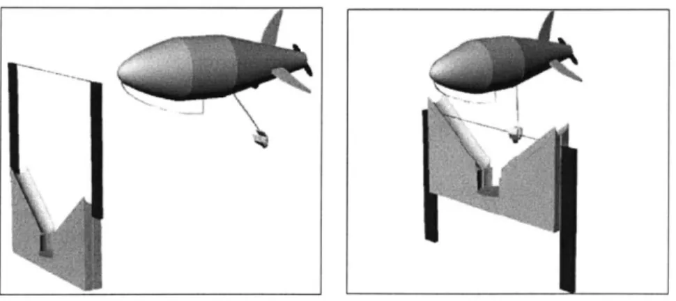
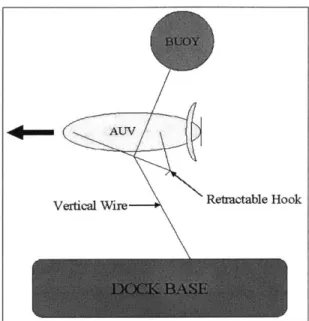
3.5 Vertical Wire and Side Hook System . . . 44
3.6 Vertical Wire and Nose Latch System . . . 46
3.6.1 Electrical Design . . . 46
3.6.2 Mechanical Design . . . 47
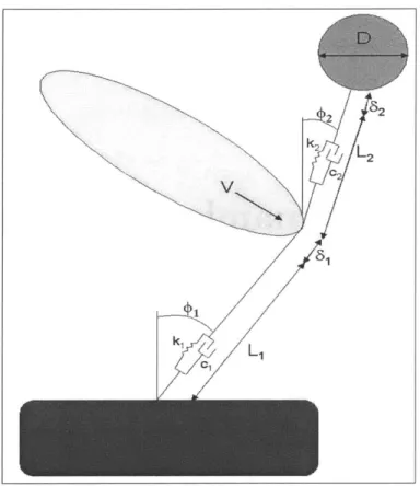
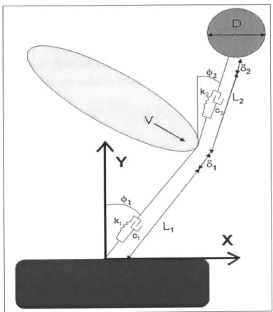
4 Mechanical Dynamic Modeling and Simulation 49 4.1 System Geometry and Assumptions . . . . 49
4.2 Lagrange's Equations . . . 51
4.2.1 Kinetic Energy . . . 52
4.2.2 Gravitational Potential and Spring Energy . . . . 53
4.2.3 Damping Potential . . . . 54
4.2.4 Generalized External Forces . . . 54
4.2.5 Differential Equations . . . 58
4.2.6 User Inputs and Initial Conditions . . . 58
4.3 Post-Simulation Calculations and Design Criteria . . . 59
4.3.1 Cable Tension . . . 59
4.3.2 AUV-Cable Interface Forces . . . 60
4.4 Limitations of the Model . . . 61
4.5 Selection of System Parameters . . . 62
4.6 N om enclature . . . 65
5 Electrical System Design 67 5.1 Fundamental Theory and Background . . . 67
5.2 LCWT Inductive Coupling . . . 68
5.2.1
Core Dimensions . . . . 705.2.2 Transformer Inductances . . . . 71
5.3 Primary Side Power Electronics . . . . 72
5.4 Secondary Side Power Electronics . . . . 74
5.5 System Losses and Efficiency . . . . 74
6 Prototype System Testing and Results 79 6.1 Prototype Construction . . . . 79
6.2 Determination of Prototype System Parameters . . . . 82
6.2.1 Equivalent Circuit . . . . 82
6.2.2 Prototype System vs. Theoretical Predictions . . . . 83
6.3 Experimental Setup and Test Plan . . . 84
6.4 Experimental Results and Trends . . . 85
6.5 Summary of Results . . . 89
7 Mechanical Latch Design 91 7.1 Description of Latch Assembly . . . 91
7.2 Operation of Latch Assembly . . . 92
7.3 Impact of the Latch on the AUV . . . 95
8 Economic Feasibility 97
8.1 Military Application . . . . 97
8.1.1 Scenario and Assumptions . . . . 97
8.1.2 R esults . . . . 99
8.2 Commercial Application . . . 101
8.2.1 Scenario and Assumptions . . . 101
8.2.2 R esults . . . 102
9 Conclusions and Future Work 105 9.1 Demand for an AUV Recharge System . . . 105
9.2 Technical Feasibility . . . 106
9.2.1 Mechanical Design and Operation . . . 106
9.2.2 Electrical Design and Operation . . . 106
9.3 Economic Feasibility . . . 107
9.4 Future W ork . . . 107
9.4.1 Improved LCWT Core Design . . . 107
9.4.2 Power Electronics Design . . . 108
9.4.3 System Integration . . . 109
9.4.4 Real Option Analysis . . . 109
References 111 A Matlab Dynamic Simulation Codes 117 A.1 Symbolic Formulation of Lagrange's Equations . . . 117
A.2 Main Simulation Program . . . 119
A.3 Function Defining ODEs . . . 121
B Determination of Prototype System Equivalent Circuit Parameters 125 C Effects of Air Gaps on Magnetizing Inductance 127 D Data From Prototype System Tests 129 D.1 Laboratory Tests . . . 129
D.2 Seawater Tests . . . 130
E Economic Analysis Calculations 131 E.1 Probability and the Normal Distribution . . . 131
E.2 Military Scenario Analysis . . . 132
List of Figures
1.1 AOSN Dock Mooring System[14] . . . . 19
1.2 AOSN Docking Mechanism[14] ... ... 20
1.3 REM US Docking System[16] ... 21
1.4 Odyssey II AUV [22] . . . .. . ... . . .. . .. . . . 23
2.1 REMUS AUV ... ... 28
2.2 LM RS AUV.. ... .... ... 30
2.3 Manta Test Vehicle ... ... ... . ... 31
2.4 LD MRUUV Concept Sketch ... 32
2.5 Net-Centric Warfare Scenario ... ... 33
2.6 Tanker AUV Concept ... . 35
3.1 Probe and Cone System ... ... 43
3.2 Horizontal Wire and Hook System . . . 44
3.3 Vertical Wire and Side Hook System . . . 45
3.4 Vertical Wire and Nose Latch System . . . 46
4.1 Simplified System Geometry . . . 50
4.2 6x19 W ire Rope Cross-section . . . 51
4.3 System Velocities . . . .
53
4.4 Coordinate System for Generalized External Forces . . . 55
4.5 AUV-Cable Interface, Case 1 . . . 60
4.6 AUV-Cable Interface, Case 2 . . . 62
5.1 Electrical System Block Diagram . . . 68
5.2 Simple LCW T Cross-Section . . . 69
5.3 Final LCW T Core Design . . . 71
5.4 Leakage Inductance per meter vs. K . . . 72
5.5 Equivalent Circuit of Primary Loop and LCWT . . . 73
5.6 Core Losses for 0.002" 3% Si-Fe Material [54] . . . 75
6.1 Si-Fe Core Segment Before Assembly . . . 79
6.2 Core Segments During Assembly . . . 80
6.3 Complete Core Assembly . . . 81
6.4 Equivalent Circuit of Prototype System . . . 82
6.5 Prototype Test Setup . . . 84
Efficiency vs. Frequency . . . . Efficiency vs. Cable Separation . . . . Overview of Latch Design . . . . Profile and Plan Views of AUV Latch Assembly. . Latch Assembly During Docking Approach . . . . Latch Assembly Closed Around Cable . . . . Detail of Core Actuator Mechanism . . . . Detail of Latch Actuator Mechanism . . . . 6.7 6.8 7.1 7.2 7.3 7.4 7.5 7.6 8.1 8.2
9.1 Improved Core Cross-Section . . . .
. . . . 8 7 . . . . 8 8 91 92 93 93 94 94 . . . . 1 0 0 . . . 1 0 3 . . . 1 0 8 C.1 Magnetic Core with Air Gaps . . . 127
Sensitivity Analysis of Military Cost Savings . . Cost Savings in Commercial Surveys . . . .
List of Tables
Battery Chemistries and Characteristics . . . Conceptual Tanker AUV Design . . . . Navy AUV Funding . . . . Chapter 2 Nomenclature . . . . Wet-mateable vs. Inductive Couplings . . . . System Parameters and Simulation Results . Chapter 4 Nomenclature . . . . Comparison of Theoretical and Actual Circuit Military Cost-Effectiveness Assumptions . . . Commercial Cost-Effectiveness Assumptions . Final System Mechanical Parameters . . . . . 1.1 2.1 2.2 2.3 3.1 4.1 4.2 6.1 8.1 8.2 9.1 Parameters 15 34 35 38 42 63 65 83 99 102 106
Acknowledgments
The author would like to acknowledge and thank the following individuals and groups for their sup-port and assistance with this project: Professor Chryssostomos Chryssostomidis; Professor James Kirtley and Professor Steven Leeb, MIT Electrical Engineering Department; MIT Seagrant AUV Laboratory research engineers Rob Damus, Sam Desset, Jim Morash, and Vic Polidoro; and the NUWC AUV Division, Newport, especially Mr. Don Ensign.
Without your help, expertise, experience, reference data, equipment loans, and corrective guidance, this work would not have been possible.
Chapter 1
Introduction
1.1
Background and Motivation
Autonomous Underwater Vehicles (AUVs) have found increasing use in recent years in commercial, military, and scientific areas. Continuing advances in technology have made AUVs an increasingly popular alternative to manned or tethered underwater systems. Specifically, improvements in underwater navigation and communication have greatly enhanced the usefulness of AUVs.
However, despite the growing popularity and wide-spread use of AUVs, one significant limitation to the systems remains. In order to operate submerged and untethered, an AUV must carry an on-board energy source. The energy source is often the driving factor in the size of an AUV, particularly as the trend toward smaller AUVs continues. Additionally, the endurance of the energy source greatly impacts the mission effectiveness of the AUV. The time required to retrieve an AUV and replenish its energy source detracts from the on-station mission time of the vehicle.
Most AUV systems in existence today are deployed and retrieved by surface ships or small boats. The deployment and retrieval evolutions are often hazardous, time-consuming, and limited by environmental conditions. Therefore, it is desirable to limit the number of deployment/retrieval cycles. This further drives the need for longer-endurance AUVs.
The purpose of this research is to develop a near-term solution to the problem of extending AUV endurance. One means of solving the problem is to develop more energy-dense power sources and more efficient AUVs. An alternative solution is to create a means of replenishing the energy source without recovering the AUV to the host platform. The former approach has been addressed extensively, resulting in continually improving AUV batteries. The latter approach has not been as widely addressed. This project attempts to solve the problem of AUV endurance by developing a system to efficiently recharge AUV batteries in situ.
The goals of this research are as follows:
1. Assess the demand for an AUV recharge system. 2. Design a prototype system.
3. Demonstrate the technical feasibility of the system. 4. Evaluate the economic feasibility of the system.
1.2
AUV Power Sources
An essential first step in assessing the demand for an AUV recharge system is to evaluate the current state of the art in AUV power sources. This section describes the types of AUV power sources available, then attempts to predict the near-term future based on current state of the art and trends.
1.2.1
Alternative Power Sources
Selection of a power source is a major factor in AUV design. An important characteristic of power sources is energy density, reported in watt-hours per kilogram (Whr/kg). Energy density is often used as a common standard for comparing power sources. Other considerations in selecting a power source include cost, safety, reliability, performance over a range of temperatures and pressures, and environmental impact.
AUV power sources can be grouped into three major categories: nuclear, combustion, and electrochemical. The first two categories will be discussed briefly, then attention will be focused on electrochemical systems, because nearly all AUVs use some form of electrochemical system.
Nuclear Power Sources
Compact nuclear reactor systems have the capability to operate as a closed system for long periods of time without refueling. Nuclear power sources have been considered and used on space vehicles for many years. At least one such system has been designed for use underwater. The system was developed by the Japan Nuclear Cycle Development Institute, and consists of a liquid metal fast reactor (LMFR) system and a closed Brayton cycle power generation system[1). The Japanese system stands 5.2m high, is 3m in diameter, weighs 26,600kg, and produces 40kW of electric power. The system is designed for use at a stationary unmanned undersea base.
While the Japanese LMFR demonstrates the feasibility of using nuclear power sources underwa-ter, the concept is impractical for most AUVs. The sheer size of the nuclear reactor and associated shielding limit its applicability to very large AUVs. Nuclear systems are prohibitively costly, and environmental and legal restrictions limit their use by most AUV operators[2]. In short, nuclear systems, while a technical possibility, are not considered a viable solution to mainstream AUV power source needs.
Combustion Power Sources
Several types of air-independent combustion power sources have been proposed and developed for underwater vehicles. The R-One Robot, built jointly by the University of Tokyo and Mitsui, is equipped with a closed-cycle diesel engine (CCDE). This AUV is 8.27m long, 1.15m in diameter, weighs 4.35 tons, and is designed for slow-speed, long-range survey operations. The CCDE generates 5kW of electricity and is equipped with diesel fuel and liquid oxygen tanks to allow 12 hours of submerged operation[3]. The R-One Robot has undergone successful sea trials and is currently operational with the CCDE system.
The Stirling engine, a dynamic heat engine using external combustion, has been used in several underwater vehicles, including manned submarines and torpedoes. Stirling engines are a viable alternative for submarines and torpedoes, given the large power and high speed requirements for
such vehicles. However, for smaller, slower vehicles like AUVs, a viable Stirling engine has yet to be produced. One proposed application of Stirling engines was in the design of a U.S. Navy diver propulsion vehicle (DPV). The DPV is roughly the size of a small AUV, with similar power requirements. The DPV system was designed to provide 470W of shaft power for a duration of 6 hours with a total weight of 68kg, or an energy density of 41.5Whr/kg[4]. This energy density is on the order of that of lead-acid batteries. Therefore, at this time there is no compelling reason to use Stirling engines in AUVs rather than much cheaper and simpler battery systems.
Electrochemical Power Sources
Electrochemical power sources can be classified into four different groups[5]: " Batteries discharged at atmospheric pressure
" Batteries discharged at ambient pressure (pressure-compensated batteries) " Seawater batteries
" Fuel cells
Several different battery chemistries have been used in AUVs. Extensive literature exists describing the relative advantages and disadvantages of the different chemistries. A detailed description of the various battery systems is beyond the scope and relevancy of this work. Table 1.1 below summarizes the most common battery chemistries and their representative energy densities, expected life (in cycles), and other pertinent characteristics[2].
Table 1.1: Battery Chemistries and Characteristics
Chemistry Energy Density Expected Life Comments
(Whr/kg) (cycles)
Alkaline 140 1 Outgassing during high temp. discharge
Lead Acid 31.5 100 Outgassing
Silver Zinc 100 30 Outgassing
Ni Cad 33 100 Flat discharge curve
Ni MH 60 500 No outgassing
Li Ion 144 500 Depth limited
Li Polymer 193 500 No outgassing
Outgassing refers to the formation of gasses, primarily hydrogen, during charging or discharging. If batteries outgas, the gasses must be vented from the cells to avoid forming an explosive environment. This becomes a significant factor in AUV design, as well as the design of underwater recharging systems.
The present state of the art in AUV batteries is lithium polymer cells. These cells have a very high energy density, low weight density, and long life. They do not outgas, which simplifies recharging. The individual cells are typically stacked in pressure-tight prismatic cases. The case
can withstand ambient sea pressure, allowing the batteries to be placed outside the pressure hull of the AUV[2].
Seawater Batteries
Seawater batteries use seawater as the electrolyte. Thus, seawater batteries have a much higher energy density than other battery types because the electrolyte is not included in the mass of the battery. Seawater batteries have been used in experimental torpedoes and small AUVs. The most common seawater battery chemistries are Mg/AgCl and Mg/02, with energy densities of 200 Whr/kg and 600 Whr/kg, respectively[5]. The drawback of seawater batteries is a very low power output density. For example, a commercially available battery produced by Kongsberg Simrad weighs 120 kg and produces only 2 watts of power, for a power density of 16.7 mW/kg. By comparison, a typical 1 kWh lithium polymer battery weighs 15 kg and can produce up to 300 watts, for a power density of 20 W/kg. Using a forced flow of seawater increases power output slightly, but it still remains significantly below other battery types. Seawater batteries may find a niche market in very small, very long-endurance AUVs, such as miniature mobile sensors. However, the power limitations prevent seawater batteries from being a significant factor in the mainstream AUV market.
Semi-fuel Cells
A semi-fuel cell is a cell that uses a solid anode and a gaseous cathode1 . The most common semi-fuel cells use aluminum as the anode and oxygen as the cathode. Energy is released by a chemical reaction between the aluminum and oxygen in an alkaline electrolyte. Power level can be controlled by varying the concentration of oxygen in the electrolyte. Semi-fuel cells can operate at ambient pressure, with performance independent of depth[7]. Operational semi-fuel cell systems have achieved energy densities of around 100 Whr/kg[5].
Semi-fuel cells are not recharged in the conventional sense. The chemical reaction consumes the aluminum anode and oxygen and produces aluminum hydroxide precipitate; thus, recharging consists of mechanically replacing the anode, changing the electrolyte, and refilling the oxygen supply. This method is much faster than most electrical battery recharging processes, but it requires significant support facilities to store fresh anodes, oxygen, and electrolyte. An additional
consideration is the need to dispose of the spent electrolyte[7].
Aluminum-air semi-fuel cells have been successfully used for many land-based applications, where the surrounding atmosphere serves as the oxygen source. Two options exist for providing oxygen in underwater applications: carry compressed gaseous oxygen, or carry oxygen in a com-pound that is easily decomposed to liberate oxygen. Both methods have been used successfully in AUVs. The XP-21 AUV, built by Applied Remote Technology, carries gaseous high-pressure (4000 psig) oxygen in two stainless steel spheres[6]. The well-known HUGIN family of AUVs uses semi-fuel cells with hydrogen peroxide (H202) as the oxygen source[8].
The HUGIN AUVs, built by Kongsberg Simrad of Norway, are designed for deep sea survey operations. The HUGIN I, built in 1995, used NiCad batteries as a power source. The HUGIN II, operational in 1998, transitioned to the Al-H202 semi-fuel cells to extend vehicle endurance. The
latest version, HUGIN 3000, became operational in 2000 and uses a larger version of the Al-H202
semi-fuel cells[5]. HUGIN 3000 is one of the leading commercial AUVs in service today, and is discussed more fully in section 2.2. The HUGIN 3000 operates at a nominal power load of 900W[5]. The semi-fuel cell power source provides 40kWh, sufficient for 40-50 hours of operation[7]. Recharge operations typically take about two hours[8].
The HUGIN AUVs use H202 rather than compressed oxygen for several reasons. First, H202 can be stored in plastic bags at ambient pressure rather than in stainless steel pressure vessels. The HUGIN systems use a simple metering pump to control the flow of H202 into the electrolyte. Second, gaseous oxygen is susceptible to pressure changes with depth, while liquid H202 is not. Finally, liquid H202 is much easier to handle than gaseous oxygen during recharge operations[8].
Fuel Cells
Fuel cells have been considered for underwater applications for several years. Fuel cells use a chemical reaction between hydrogen and oxygen to release energy in the form of DC electricity. Several types of fuel cells exist, including Proton Exchange Membrane Fuel Cells (PEMFC), Solid Oxide Fuel Cell (SOFC), and Solid Polymer Fuel Cells (SPFC). Underwater applications typically use the SPFC type because of their smaller size and relatively robust design and reliability[9]. A more detailed description of fuel cells can be found in [10].
A major problem with using fuel cells underwater is storage of the reactants. As in semi-fuel cells, the reactants are carried either as compressed gasses, or as compounds that decompose or react to liberate the gas. A third option is to carry the reactants as liquids, but this requires cryogenic systems that are impractical for most AUVs. Compressed gas storage requires large pressure vessels and creates an explosive hazard if not handled properly. On the other hand, storage as a compound is less efficient, because only a fraction of the stored compound is converted to hydrogen or oxygen. Additionally, most storage compounds are highly reactive and require special storage precautions. Typical compounds used are boron hydride to produce hydrogen, and hydrogen peroxide to produce oxygen [5].
The energy density of fuel cells, based solely on weight of reactants, is approximately 2000Whr/kg. However, in order to make a fair comparison with other power sources, the energy density of the entire fuel cell system must be calculated. A complete system sized for a typical AUV and using compressed gas storage spheres would have an energy density of about 130Whr/kg[5]. The energy density of fuel cell systems increases with size, since a larger percentage of total weight can be dedicated to reactants. This is one important reason behind the lag in development of small-scale AUV fuel cell systems.
Fuel cells have been used successfully in several manned submarine designs. The German Class 212 submarines feature nine PEMFC modules capable of producing 34kW each. The Class 214 submarines feature two 120kW PEMFC modules with roughly the same size and weight as the 34kW modules. The fuel cells for both submarine classes are built by Siemens, and use metal hydride and liquid oxygen as reactants[11].
Despite the obvious benefits of fuel cells, only one AUV has successfully operated with a fuel cell power source and been reported in the literature. The AUV Urashima, developed by the Japan Marine Science and Technology Center (JAMSTEC) for deep-sea exploration, conducted successful sea trials in August 2003. The Urashima is 10m long and weighs approximately 10 tons. Its power source is a 4kW SPFC, using metal hydride and high-pressure gaseous oxygen as reactants[12]. To date, no smaller AUV fuel cell systems have been reported.
1.2.2
Near-term Future Predictions
The purpose of this analysis is to attempt to predict the state of AUV power source technology in the near future (five years), as this will dictate the demand (or lack of demand) for a battery recharge system. Based on the information presented above, the following conclusions are reached: 9 Lead-acid, alkaline, and lithium polymer batteries will continue to be the most widely used
AUV power sources.
* Seawater batteries and semi-fuel cells will have niche markets, but will not appeal to the mainstream AUV market.
9 Fuel cells remain too costly and complicated to see widespread proliferation in the market. These conclusions are justified below.
Most AUVs in service today conduct operations on the order of a few hours in duration. The power demands for missions of this duration can be easily supplied by lead-acid, alkaline, or lithium polymer batteries. Most AUV users do not find it necessary or cost-effective to invest in emerging technologies like fuel cells. The argument can be made that the current operational profile is driven by the available power sources, and that if higher-endurance power sources were available users would change their operations. However, the fact remains that most AUV missions today can be accomplished using conventional battery power sources.
Seawater batteries simply cannot provide the levels of power required by most AUVs. Adding more sensors, communication systems, manipulator arms, etc. to future AUVs will further increase the power demands, making seawater batteries even less viable as time goes on. Semi-fuel cells have energy densities lower than alkaline or lithium polymer batteries (10OWhr/kg compared to 140Whr/kg and 193Whr/kg, respectively), but significantly higher cost and complexity. The one advantage of semi-fuel cells, the rapid recharge time, is not deemed to be compelling enough to encourage their use. Furthermore, semi-fuel cell use requires a shift away from conventional recharging methods.
Despite advances being made in the automotive and power generation industries, fuel cells are still considered risky technology. This tends to increase the discount rate used by companies to calculate the value of a potential investment. The effect of the higher discount rates is to make fuel cell projects appear less financially attractive than alternative, more conventional projects. Additionally, higher discount rates imply a higher cost of investment capital; thus, capital-intensive fuel cell projects appear even more expensive than alternatives [13]. The result of this twofold effect is that only very large organizations, like governments and possibly multi-national corporations who operate large numbers of AUVs, will venture into the fuel cell arena. The general trend in AUV use is exactly the opposite, tending towards many small operators running a few AUVs. Thus, fuel cells will continue to lag behind conventional batteries for the near future in the mainstream AUV market.
1.2.3
Motivation for a Battery Recharge System
The above arguments indicate that batteries (lead-acid, alkaline, or lithium polymer) will continue to be the AUV power source of choice for the near future. However, there are advantages to be
gained by extending AUV endurance2, as discussed in section 1.1. Therefore, it is worthwhile to invest in development of an underwater battery recharging system. The remainder of this work describes such a system and evaluates its technical and economic feasibility.
1.3
Previous Docking and Recharge Systems
A literature search was conducted to identify previous efforts in the area of AUV docking. A number of AUV docking and recharge systems have been designed and built. The following systems and descriptions are representative of the current state of the art in docking and recharge systems.
1.3.1
AOSN Dock
The Autonomous Ocean Sampling Network (AOSN) docking system was a joint effort between the Woods Hole Oceanographic Institute (WHOI) and the Massachusetts Institute of Technology (MIT) Sea Grant Laboratory. The AOSN concept involves a number of AUVs deployed at a remote site around a docking station for extended periods of time. It was designed to use the MIT Odyssey II AUV, which is described in section 1.5. The AOSN dock provides data download and battery recharge capability to the AUVs. The system consists of several components that stretch from the surface to the ocean floor[14]. Figure 1.1 illustrates the entire system.
Figure 1.1: AOSN Dock Mooring System[14]
The docking mechanism consists of a V-shaped titanium latch with a spring-loaded capture bar mounted on the nose of the AUV. The AUV drives into the 1.5m long vertical docking pole, and
2Endurance here is defined as total time away from the host ship, not necessarily battery life. -,with c LINKS
1'0 MI?f#h 15 rnHOSE
7 1 66 , S'NTACT)C $PtffRE
4-CONtACOR CABLE, 425 SOC ' DOCKING SIA IW
&A 77U Y/7NS rRU&4. NT GArE
(40) 17 irch CLASSSALLS
WRE ROP)
(JO) 17 inch 0ASSIIALLS OIALM ACOUSIC RELEASSO
the AUV's forward momentum pushes the capture bar aside and positively latches the AUV to the pole. The latching operation is completely passive. Undocking is accomplished by releasing the capture bar via a rotary actuator, then backing the AUV away from the pole. The docking system is omnidirectional and has a 1.5m high and 0.6m wide target area, determined by the pole height and tine separation, respectively[15].
The AOSN dock uses an ultra-short baseline (USBL) system on the AUV and a 2kHz acoustic beacon on the dock for homing. Power and data transfer occurs through inductive cores, eliminating the need for wet-mateable conductive contacts. One core is mounted on the under side of the AUV nose, the other on the upper side of the lower dock carriage. Once the AUV is attached to the pole, the cores are aligned and brought into contact by driving the lower dock carriage up the pole, forcing the AUV against the upper carriage[15]. Figure 1.2 shows a drawing of the docking mechanism.
Figure 1.2: AOSN Docking Mechanism[14]
The AOSN system has been tested at sea several times, beginning in Oct. 1997, with mixed results. The inductive data and power transfer were successfully demonstrated, with efficiencies of around 80% (including the power electronics on both ends)
[15].
The mechanical system experienced problems during deployment. It is believed that the docking pole was bent during deployment, causing the moving carriage to jam and preventing positive connection with the AUV. The system was also very difficult to deploy, taking 22 hours in moderate sea conditions. WHOI has since corrected most of the system problems and is developing a new simpler system with fewer moving parts[14].1.3.2
REMUS Dock
WHOI has developed a docking system for the REMUS AUV3. The REMUS dock consists of a horizontal cylindrical housing and a funnel cone. The cone opening is
1m
in diameter, and the cylinder is0.25m
in diameter. The AUV enters the cone nose-first and is funneled into the cylinder. Once in the cylinder, a clamping motor drives a leadscrew up from the bottom and clamps the AUV securely in the cylinder. A second motor then drives the power and data connections together on the nose of the AUV[16]. Figure 1.3 shows a schematic of the REMUS dock.j-Transponder
Fr1-USBL Array
C c lampingUnit ote Clecontct Aontact
Motor
DockigTb Contact Unit
Oamnping Mtr Retainer
Docking Cone
Figure 1.3: REMUS Docking Systemn[16]
The original REMUS dock used a single sealed contact on the AUV nose for power and data transfer, with the return current traveling through seawater[16]. This design was simple and robust, but suffered very low data rates. The system was updated to a two-wire power and Ethernet connection, resulting in faster battery charging and data download times[17]. The REMUS dock uses an acoustic USBL homing system{16].
A militarized version of REMUS is used by the U.S. Navy. The docking system is also of interest
to the Navy. Therefore, improvements are underway to reduce the size and weight of the dock, making it easily deployable by divers. Additional work is ongoing to extend the endurance and improve the data transfer capability of the dock[18].
1.3.3
FAU Ocean Explorer Dock
Florida Atlantic University (FAU) has designed and built the Ocean Explorer series of AUVs. The Ocean Explorer is a modular AUV, with interchangeable mission-specific nose cones. Therefore, a nose docking system, such as the REMUS dock, is undesirable. FAU has developed a docking system that uses a belly-mounted stinger instead. The docking station consists of a four-piece spring loaded mechanism supported by a vertical pole. The AUV swims over the dock, the stinger enters the docking mechanism from any direction, and is trapped in a central cavity. The electrical connection is then made through the center of the dock to the stinger. The FAU dock is omnidirectional, but requires precise altitude control to catch the stinger in the dock mechanism[19].
3
1.3.4
Flying Plug Socket
The Flying Plug AUV (described in section 2.1.2) uses a docking system very similar to the REMUS dock. The Flying Plug dock is referred to as the Socket. It uses a cone and cylinder system to capture the AUV and align the power and data connections. A unique feature of the Socket is the use of a combination acoustic/optical homing scheme. An acoustic beacon is used to get the AUV close to the dock (i.e., within a few meters), then an optical tracking system is used for final alignment and approach. The optical tracking system is similar to those used by laser-guided munitions. The Socket also uses optical data transfer, rather than conductive or inductive electrical couplings [20].
1.3.5
Eurodocker
Eurodocker is a project funded by the European Commission, DG XII, under the Marine Science and Technology program (MAST). The goal of the project is to develop a universal garage-type docking station that can be used by a variety of AUVs. A prototype has been built and successfully tested using Maridan's Martin AUV. The dock consists of a tubular frame box structure that completely encloses the AUV, providing physical protection while docked. An active shock absorption system using water bags absorbs the impact of the docking AUV. A variable buoyancy system allows precise depth positioning of the dock. Power and data transfer is via wet-mateable pin connections. Two Eurodocker configurations are envisioned, one towed by a support ship and the other permanently deployed on the ocean floor. The Eurodocker project represents one of the first efforts to create a universal dock for use by commercial work-class (as opposed to research or military) AUVs[19].
1.3.6
U.S. Navy Torpedo Tube Launch and Recovery System
The Navy's Torpedo Tube Launch and Recovery (TTLR) system is being developed to launch and recover AUVs from a submerged submarine. While not a true docking system in terms of battery recharge and data transfer, the TTLR system illustrates the use of an articulated arm to physically capture and retrieve an AUV. The arm deploys from the upper torpedo tube and extends an aft-facing receiver cone. The AUV approaches on a course parallel to the submarine, using acoustic homing. A retractable probe on the AUV nose is driven into the receiver cone. A support ring then grabs the mid-body of the AUV, creating a secure two-point connection. The arm maneuvers and forces the AUV into the lower torpedo tube, tail-first. The arm is then retracted into the upper tube and both tube shutter doors are closed[21]. The TTLR system is being developed by NUWC and built by Boeing. A prototype system has been built and installed on a barge, and testing is ongoing. The timeframe for installation on a submarine is unclear, dependent on the prototype results[21].
1.4
Overview of Proposed System and Design Goals
The primary goal of the design phase of this work was to develop a docking and recharge system compatible with all present and near-term future U.S. Navy AUVs. A secondary goal was to extend the compatibility of the system to the commercial AUV market. A major factor distinguishing the present work from previous systems (with the exception of Eurodocker) is the attempt to make
the system universally compatible with a range of AUVs. It was decided early in the project that the docking system would only provide battery recharge power, and not data interface capability. Ongoing advances in optical and acoustic data transfer techniques, along with the growing need for real-time data, will soon make periodic data dumping techniques obsolete.
1.5
Description of Odyssey II AUV
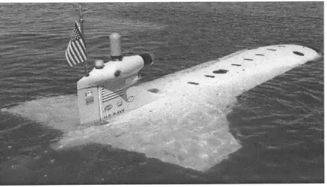
The Odyssey family of AUVs were designed and built by MIT's Sea Grant AUV Laboratory. The Odyssey II is 2.2m long and 0.58m in diameter. It has a weight of 200kg in air, and a net buoyancy of 0.5kg in water. The AUV has a depth rating of 3000m, and can reach speeds up to 3 knots. When the vehicle is outfitted with a lkWh lithium polymer battery, it has a mission endurance of about 4 hours[22]. Figure 1.4 shows a photo of the Odyssey II AUV.
Figure 1.4: Odyssey II AUV[22]
The Odyssey II was selected as the test bed platform for which the proposed recharge system was designed. The primary reason for this was physical availability and familiarity, since the current research also occurred at MIT's Sea Grant AUV Laboratory. Furthermore, Odyssey II serves as a representative medium-sized, multi-purpose AUV and thus is a good target around which to design.
1.6
Thesis Outline
The remainder of this report consists of the following:
" Chapter 2 provides an analysis of the economic demand, both military and commercial, for a recharge system.
" Chapter 3 describes the analysis of alternative designs considered and the final chosen design. " Chapter 4 analyzes the dynamic mechanical behavior of the chosen design, using a computer
simulation.
" Chapter 5 describes the process of designing the electrical coupling between the dock and
the AUV.
" Chapter 7 describes the mechanical design of the latch interface between the dock and the AUV.
" Chapter 8 assesses the economic feasibility of the proposed system for both military and commercial markets.
Chapter 2
Demand for an AUV Recharge
System
2.1
Military Market
The United States Navy is one of the leading users of AUVs in the world. Furthermore, the Navy has plans to greatly expand its use of AUVs in the near future [23]. Navy acquisition funding for AUV programs more than doubled from FY02 to FY03[24]. As such, the U.S. Navy is the primary target market for an AUV battery recharge system.
2.1.1
Roles for Navy AUVs
AUVs have the potential to perform four broad military roles: maritime reconnaissance, under-sea under-search and survey, communications and navigation, and submarine tracking[25]. Each role is described in detail below.
Maritime Reconnaissance
The number one mission priority for AUV application by the U.S. Navy is Maritime Reconnaissance [23]. AUVs are capable of performing a number of reconnaissance tasks currently performed by manned platforms such as submarines or aircraft. The main advantage of AUVs in reconnaissance missions is increased stealth. AUVs could be covertly deployed into areas that are inaccessible to submarines or aircraft, such as politically denied areas or extremely shallow water. An AUV could operate undetected in these areas for long periods of time, gathering valuable information in the process. Three main reconnaissance uses of AUVs are intelligence, surveillance, and reconnaissance (ISR); battle damage assessment (BDA); and remote target designation[25)1.
ISR is a ready-made mission for an AUV. AUVs are capable of gathering visual, electromagnetic, or acoustic data. This data can be relayed near real-time back to a manned platform, or it can be stored onboard the AUV until it returns to the host platform. It is understood that stealth is compromised during communication. In essence, the AUV would operate as a set of remote eyes and ears for the host platform.
BDA is an increasingly important mission in this era of limited, precision warfare. Presently, satellite or aircraft photography is relied upon for most BDA. AUVs could perform this mission with greater stealth and potentially greater accuracy. However, AUVs could only perform BDA on ship or coastal land targets, since visual contact would be required.
The third potential reconnaissance mission of AUVs is remote target designation. AUVs could be equipped with laser target designators and used to identify targets for cruise missile or aircraft attacks. However, as with BDA, this role would be limited to ship or coastal targets.
Undersea Search and Survey
The oldest and most highly developed military application of AUVs is Undersea Search and Survey. The primary advantage of AUVs over alternative platforms in this mission area is the AUV's ability to operate in regions or environments inaccessible to manned vehicles. A secondary advantage of AUVs is that they can often perform a search or survey mission more economically than a manned vehicle. Three main search and survey applications of AUVs are mine countermeasures, salvage, and hydrographic survey[25].
Mine countermeasures (MCM) was the first military application of AUVs[25]. The appeal of using unmanned vehicles to detect and detonate mines is readily apparent. Minefields can be safely cleared without needlessly risking human life. Additionally, AUV systems can clear mines faster and more efficiently than human operators. Finally, an AUV MCM system could have the added advantage of stealth if deployed from a submarine. Thus, a minefield could conceivably be neutralized without the opponent realizing it.
Underwater military salvage is another area in which AUVs could have a significant impact. AUVs could be made capable of performing all aspects of a salvage operation, from initial detection to photography and videotaping to actual retrieval of objects. AUVs are more advantageous than human divers because they can operate at deeper depths and remain on station longer. Additionally, AUVs can safely operate in salvage sites that may be contaminated by hazardous materials or nuclear radiation[25].
The third potential search and survey mission of AUVs is hydrographic and oceanographic sur-vey. This mission covers a wide range of activities, including but not limited to bottom surveys for the purpose of charting, plotting of ocean currents, weather observation, and survey of amphibious landing zones. Clearly some of these activities are not strictly military in nature and overlap with commercial applications of AUVs.
Communication and Navigation
The communication and navigation role is a key component of the other AUV missions in addition to being a stand-alone role. An essential part of any AUV mission is the ability to communicate the information collected back to the host platform. An AUV must also be able to navigate and know its position with great precision to accomplish most missions. As for stand-alone communica-tion/navigation missions, AUVs could potentially function as mobile communication relay stations or as a backup to satellite systems[25].
An AUV could function as a communication relay simply by positioning itself midway between two communications stations, within line of sight (LOS) of each. The AUV would surface, or extend an antenna mast above the surface. Communications could then be conducted using less detectable LOS transmissions rather than satellite transmissions. An AUV could also act as a
submerged acoustic relay station. Additionally, AUVs could be used as mobile satellite relay stations (again requiring the AUV to be on or near the surface), creating an additional link in the chain between transmitter and receiver. The purpose of this would be to make it more difficult to triangulate the location of a transmission source. This role could be extremely useful in submarine communications, where remaining undetected is a priority.
A group of AUVs could also potentially be organized into an underwater, mobile communica-tions/navigation network. Such a system could be vital in case of a Global Positioning System (GPS) failure or jamming by a hostile force[25]. This system would, however, be very limited in range due to underwater acoustic limitations.
Submarine Tracking and Trailing
Submarine tracking and trailing is the most visionary of the potential AUV applications and the one requiring the most technological developments to reach fruition. The ultimate goal of this application is to create a fully autonomous system capable of detecting a submarine and tracking it for extended periods of time over long distances of open ocean[25]. This capability would supple-ment the activities of manned submarines, thereby freeing them to perform other tasks. This goal will be very difficult to fully achieve. To put it in perspective, today this mission is challenging even for a billion dollar nuclear submarine manned with 120 men. Attempting to perform the same mission with an affordable unmanned system is a monumental undertaking and will require extensive long-term planning and investment.
In the shorter term, AUVs could perform some limited portions of the anti-submarine warfare (ASW) mission. One such mission would be to function as a mobile sonar platform for initial detection of opposing submarines[25]. The AUVs would function similar to the existing sonar arrays stretched across regions of the ocean floor, but with the added benefit of mobility. An AUV sonar platform would have an advantage over a manned submarine in that the AUV is much smaller and potentially quieter, due to less machinery noise. Therefore, the AUV could detect an opposing submarine earlier due to less own-noise interference, and would also be less likely to be
counter-detected by the opponent.
Several major obstacles stand in the way of creating AUVs to perform this mission. First, speed limitations on existing AUVs would severely limit their ability to track a high-speed nuclear submarine. Second, existing ASW sonar systems are too large to be mounted on an AUV. Third, the necessary communications links do not currently exist. However, many experts believe all these obstacles can be overcome and a fully autonomous submarine tracking system will someday be developed[25].
2.1.2
Summary of Navy AUV Programs
The Navy's development and use of AUVs is guided by The Navy Unmanned Undersea Vehicle
(UUV) Master Plan [23]2. Implementation of the plan is carried out by the Naval Sea Systems
Command (NAVSEA), PMS403. Several research AUV programs, one of which is the MIT Odyssey described in section 1.5, are sponsored by the Office of Naval Research (ONR). Development of Navy AUV programs is done primarily by the Naval Undersea Warfare Center (NUWC) and the 2The Navy term UUV is synonymous with the generally-accepted term A UV, and the two are used
Space and Naval Warfare Systems Center (SPAWAR). The Navy currently has several tactical AUV systems either operational or in development for near-term deployment. Several other systems and concepts are being considered for long-term use. The systems are described below, starting with the most mature first.
REMUS/SAHRV
The Remote Environmental Monitoring UnitS (REMUS) is a system developed jointly by NUWC and the Woods Hole Oceanographic Institute (WHOI), and manufactured commercially by Hydroid, Inc. of East Falmouth, MA. It is a low cost, light weight, system designed for operation using a laptop computer. The AUV is 7.5" in diameter, 54" long, and has a nominal weight of 64 lbs. REMUS is a mature system, with over five years of product development and thousands of hours of field operations, designed for use by a wide range of both commercial and military customers. The system has been used for a variety of missions, including hydrographic surveys, harbor security op-erations, debris field mapping, fishery opop-erations, mine counter measure opop-erations, environmental monitoring, search and salvage operations, and scientific sampling and mapping[26].
The present configuration of REMUS is powered by a 1 kWhr rechargeable lithium ion battery. The vehicle has a maximum sortie endurance of 22 hours at optimum speed (3 knots) [26]. Figure 2.1 is a photograph of a REMUS AUV.
Figure 2.1: REMUS AUV
The militarized version of REMUS is the Semi-Autonomous Hydrographic Reconnaissance Ve-hicle (SAHRV) system. The system was acquired by the Navy to satisfy the "requirement for a small shallow water un-manned underwater vehicle (UUV) to conduct reconnaissance in support of amphibious landing, hydrographic mapping, and mine countermeasures operations" [27]. The SAHRV system is self-contained and can be easily deployed, operated, and retrieved from a small boat by Navy special warfare personnel. The system is identical to the commercial REMUS, with the exception of sensors and communication suites, the details of which are classified[27].
NMRS
The Near-term Mine Reconnaissance System (NMRS) was developed in the mid 1990s as a limited stop-gap solution to unmanned mine reconnaissance. The NMRS is deployed and recovered via a submarine torpedo tube. The vehicle is backed out of the tube tail first, and recovered into the tube nose first. The vehicle is 21" in diameter and 206" long, very similar in size and appearance
to a Mk48 torpedo. It carries forward-looking and side-looking sonar capable of detecting mine-like objects. The NMRS is powered by rechargeable silver-zinc batteries[28].
The NMRS is not a true AUV, because it normally does not operate autonomously. The vehicle is remotely controlled from the submarine via a fiber optic cable. The vehicle does have a limited autonomous capability to return to the submarine and be recovered in the event the fiber optic cable fails[28].
The NMRS was planned to reach initial operational capability (IOC) in FY98[28]. However, it has never achieved widespread operational use and remains in a fleet contingency status[24]. Despite this fact, the NMRS was an important learning step in the development of the next-generation minehunting system.
Flying Plug
The Flying Plug is a small AUV developed by SPAWAR to function as a connectivity channel. The vehicle is 9" in diameter and 50" long. It is sized so that it can be launched from the trash disposal unit of a submarine. The system is expendable, meaning the vehicle is not recovered to the submarine[20].
The Flying Plug is designed to dock with a remote sensor or information node and transfer data back to the host submarine. The vehicle is tethered to the submarine by a 20 km long fiber optic cable. The cable provides guidance commands to the vehicle and serves as the data link back to the submarine. The cable allows up to 120 Mbit/second of data transfer[20]. A critical element of the system is the docking station described earlier in section 1.3.4.
A potential application of the Flying Plug is to service and retrieve data from a network of remote underwater sensors. Another potential use is the transfer of data or tasking information to the submarine from a shore command via a submarine cable. A long submarine cable would be deployed across the ocean floor, with Flying Plug connection points spaced along its length. The submarine would deploy a Flying Plug to dock with the nearest connection point and retrieve any waiting data or messages[20]. This would eliminate the need for the submarine to periodically come to periscope depth and risk detection.
A major drawback of the Flying Plug system is the lack of real-time data retrieval. Unless the submarine is continuously tethered to the remote node, there will always be an inherent time lag. As underwater acoustic communications continue to improve in speed, range, and bandwidth, the utility of the Flying Plug system will most likely fade away.
LMRS (AN/BLQ-11)
The Long-term Mine Reconnaissance System (LMRS) is the follow-on program to NMRS. The system also carries the Navy designator AN/BLQ-11. The LMRS vehicle is 21" in diameter, 240" long, and weighs 1.4 tons. The system is autonomous, with no fiber optic tether. It is equipped with both acoustic and RF communication systems. The LMRS sensor suite is more capable than the NMRS sensors. The design goals for the LMRS are a sortie range of 120 nm, area coverage of 50 square miles per day, and nominal endurance of 62 hours. The LMRS vehicle is powered by rechargeable lithium ion batteries[29]. Figure 2.2 below shows the LMRS vehicle.
A significant element of the LMRS is the TTLR system described in section 1.3.6. TTLR allows the LMRS vehicle to be launched from the tube in the same manner as a torpedo, then be recovered
Figure 2.2: LMRS AUV
tail first into the tube. This arrangement greatly simplifies operations inside the torpedo room of the submarine.
The LMRS is built by Boeing. The system has been tested and is projected to reach IOC in FY04, with a total of 6 units in service by FY07[24].
MRUUV
The Mission-Reconfigurable UUV (MRUUV) is a concept being developed as a follow-on to the LMRS system. The conceptual vehicle is 21" in diameter, 240" long, and weighs approximately 2800 lbs. It is designed to be launched and recovered from a submarine torpedo tube or surface support ship. The MRUUV has a projected sortie range up to 120 nm and sortie endurance up to 40 hours. The power source is lithium ion batteries, with a possible transition to fuel cells later in development [30].
The MRUUV contains a 5 ft3 payload bay that can be loaded with a variety of sensor or communication payload modules. The vehicle can be easily reconfigured for different missions onboard the host vessel. Additionally, the MRUUV features improved autonomous control, better threat avoidance capability, and better net-centric connectivity than the LMRS. The MRUUV system will use the same launch and recovery system as the LMRS[30].
Detailed design of the MRUUV is expected to begin in FY04. Testing will begin in FY07, with IOC projected for FY09[24].
Manta Test Vehicle
Manta is a test bed vehicle designed and built by NUWC. It has been operational since 1999, with over 90 successful in-water demonstrations to date. The vehicle represents a departure from traditional torpedo-shaped AUV designs. It is also significantly larger than other AUV systems, weighing 8 tons in air and displacing 16 tons of seawater. Manta has a top speed of 8 knots and an endurance of 3-6 hours, depending on payload[31]. Figure 2.3 shows a photograph of the Manta test vehicle.
Manta serves as a valuable platform to test new AUV technologies and operational concepts. The Manta vehicle has successfully conducted autonomous launches of a MK48 torpedo, a prototype MRUUV, and a REMUS AUV. This is a critical step in the development of cascading AUV systems, where a large AUV deploys and possibly recovers smaller AUVs. Manta features an extensive ISR suite, and has demonstrated both autonomous and remotely controlled surveillance missions. The vehicle has also demonstrated that autonomous avoidance of submerged obstacles by an AUV is
Figure 2.3: Manta Test Vehicle
possible. Manta has also been used extensively to test acoustic and RF connectivity between AUVs and submarines or shore bases. Several other demonstrations are planned by NUWC for the coming years[31].
The existing Manta is a one-of-a-kind, prototype system. It is unlikely that the system will ever see fleet operations in its current configuration. However, the vehicle's success as a demonstration platform has supported interest in developing conformal AUVs. Conformal AUVs are unconven-tional shaped vehicles designed to fit into cavities on the hulls of future submarines or surface ships, thus conforming to the hull shape.
LD MRUUV
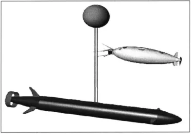
The Large Displacement Mission-Reconfigurable UUV (LD MRUUV) is a concept being considered to expand the capabilities of Navy AUVs. The exact dimensions of the vehicle are yet to be determined, but it will be larger than the conventional 21" diameter. This concept represents a significant departure from current torpedo tube launched AUVs. The larger size will allow increased time on station, more robust missions, increased modularity, and multiple missions per sortie. Potential new roles for the system include deployment of cascading vehicles, mine neutralization, and submarine track and trail[30]. Figure 2.4 shows a conceptual sketch of the LD MRUUV.
The LD MRUUV will require development of a new launch and recovery system. It is expected that the vehicle could be deployed from the payload bays of future submarines, or from surface ships.
An analysis of alternatives (AOA) for the LD MRUUV system is currently being conducted by NUWC. A selection will be made and preliminary design is planned to begin in FY05. Detailed design is expected in FY07, testing in FY10, and IOC in FY11[24].