Publisher’s version / Version de l'éditeur:
Cement and Concrete Research, 19, November 6, pp. 957-967, 1989-11-01
READ THESE TERMS AND CONDITIONS CAREFULLY BEFORE USING THIS WEBSITE. https://nrc-publications.canada.ca/eng/copyright
Vous avez des questions? Nous pouvons vous aider. Pour communiquer directement avec un auteur, consultez la première page de la revue dans laquelle son article a été publié afin de trouver ses coordonnées. Si vous n’arrivez pas à les repérer, communiquez avec nous à [email protected].
Questions? Contact the NRC Publications Archive team at
[email protected]. If you wish to email the authors directly, please see the first page of the publication for their contact information.
NRC Publications Archive
Archives des publications du CNRC
This publication could be one of several versions: author’s original, accepted manuscript or the publisher’s version. / La version de cette publication peut être l’une des suivantes : la version prépublication de l’auteur, la version acceptée du manuscrit ou la version de l’éditeur.
For the publisher’s version, please access the DOI link below./ Pour consulter la version de l’éditeur, utilisez le lien DOI ci-dessous.
https://doi.org/10.1016/0008-8846(89)90109-9
Access and use of this website and the material on it are subject to the Terms and Conditions set forth at
Stress development at the cement paste-steel interface for thin cement
paste coatings
Beaudoin, J. J.; Feldman, R. F.; Ramachandran, V. S.
https://publications-cnrc.canada.ca/fra/droits
L’accès à ce site Web et l’utilisation de son contenu sont assujettis aux conditions présentées dans le site
LISEZ CES CONDITIONS ATTENTIVEMENT AVANT D’UTILISER CE SITE WEB.
NRC Publications Record / Notice d'Archives des publications de CNRC:
https://nrc-publications.canada.ca/eng/view/object/?id=806465d9-fdd2-45c6-948c-5c516c51ad4e https://publications-cnrc.canada.ca/fra/voir/objet/?id=806465d9-fdd2-45c6-948c-5c516c51ad4eS e r
TH1
National Research Conseil national
N21d
*
I
Council Canada20.
1632
de recherches Canadac. 2 I
Institute for
lnstitut de
- - - _ _
Research in
recherche en
Construction
construction
Stress Development at the
Cement Paste-Steel Interface
for Thin Cement Paste
Coatings
by J.J.
Beaudoin, R.F. Feldman and V.S. Ramachandran
Reprinted from
Cement and Concrete Research
Vol. 19, No.
6,1989
p. 957-967
(IRC Paper No. 1632)
NRC - CISTI ;
L I B R A R Y
-NRCC 31 097
1
F E o 32
1990
!
!
B I B L I O T H ~ Q U E
t 1I R C
1
3
CNRC - -;7T ..- -L-..-LI.P-I
-
lum?v&
Les auteurs decrivent bribvement une nouvelle technique permenant de dkterminer les contraintes B l'interface acier-ciment dans le cas & minces revetements & pate de ciment. 11s pdsentent une s f i e de courbes contraintes interfaciales-temps d'hydratation pour m i s sys&mes de mamce : ciment
+
silice fine, ciment+
carbonate & calcium, et aluminate tricalcique+
gypse. 11s examinent les mCcanismes qui peuvent &reB
l'origine des contraintes. - --
- - ----
--- - -I
1i
CEMENT and CONCRETE RESEARCH. Vol
.
19, pp. 957-967, 1989. P r i n t e d i n t h e USA. 0008-8846/89. $3.00+00. Pergamon Press p l C.STRESS DEVELOPMENT AT THE CEMENT PASTE-STEEL INTERFACE FOR THIN CEMENT PASTE COATINGS
J.J. Beaudoin, F.R. Feldman and V . S . Ramachandran B u i l d i n g M a t e r i a l s S e c t i o n
I n s t i t u t e f o r Research i n C o n s t r u c t i o n N a t i o n a l Research C o u n c i l Canada Ottawa, O n t a r i o KIA 0 ~ 6 , Canada
(Communicated by M. aim on)
( ~ e c e i v e d March 10, 1989) ABSTRACT
A novel technique for determining the development of stress at the steel- cement interface for thin cement paste coatings is briefly described. A series of interfacial stress-hydration time curves are presented for three matrix systems: cement
+
silica fume, cement+
calcium carbonate, and tricalcium aluminate+
gypsum. Results are discussed in terms of possible mechanisms of stress development.INTRODUCTION
The evolution of advanced cement-based materials includes new developments in composite technology. Novel fiber or particle-reinforced cement systems are likely to find new and diverse applications such as repair and rehabilitation of the concrete infrastructure. Engineering the properties of the matrix-inclusion interface is of prime importance as composite behavior can I
I
be controlled in this manner. Bond strength of the fiber-matrix interface, for example, influences the development of composite strength and toughness. A novel technique (Overhanging Beam Method, OBM) for determining bond strength of cement paste to steel has been developed1.
The method is a two step process. First the interface stress due to the hydration process isdetermined. The second step involves the superposition of additional stress on the specimen by an environmental change eg. lower humidity until the cement
9 5 8
J.J. Beaudoin, et al.
Vol. 19, No. 6
coating autodebonds. The bond strength is computed as the algebraic sum of the stress determined in both steps.The OBM technique has several
advantages: the application of external load is not required; bond strength at very early ages can be determined; the interface stress arising from the
hydration process itself can be followed. The latter measurement is a precursor to the determination of the true bond strength and is the subject of this
communication. Interface stress due to hydration is dependent on the
composition of the matrix and can be a significant component of bond strength. This method is particularly relevant to computations of fiber stress for prediction of composite behavior. A component of the total stress transferred to the fiber is due to the hydration process. It is generally not taken into account in
conventional testing. Development of stress at the steel-matrix interface during hydration at 100% RH was followed using the novel Overhanging Beam Method for the following: cement with silica fume addition; cement with calcium carbonate addition; tricalcium aluminate with gypsum addition.
EXPERIMENTAL
Materials
Portland Cement: The composition of the portland cement used is as follows: SiO2 = 22.00%; A1203 = 4.88%; Fee03 = 1.93%; CaO = 63.29%; MgO = 4.24%;
SO3
-
1.95%; Na20 = 0.1 7%; K20 = 0.78%.Iricalcium S i l i c a : Triclinic C3S was supplied by the Portland Cement Association, Skokie Illinois. The Blaine surface area is 3247 cm21g.
Tricalcium Aluminate: C3A was supplied by the Tetratech Co. Analysis gives the following results: CaO = 61.6%; A1203 = 37.8%; MgO = 0.5%; Na2O = 0.1 %. The nitrogen surface area = 0.58 m2lg.
Silica Fume: Microsilica was supplied by the SKW Co., Montreal Quebec. The composition is as follows: SiO2 = 95%; Carbon = 1.56%; K20 = 0.27%;
Na20 = 0.1 %. The nitrogen surface area = 21.0 m21g.
Gv~sum: Reagent grade gypsum was supplied by Fisher Scientific Co. The nitrogen surface area is 10 m2lg.
Calcium Carbonate: CaC03 was supplied by Anachemia Chemical Co. The nitrogen surface area is 6.5 m21g.
Su~er~lasticizer: A sulfonated melamine formaldehyde superplasticizer in amounts up to 0.3% by weight of cement was used to prepare mixes containing silica fume and calcium carbonate.
Stet& Commercial feeler gauge stock with thicknesses of 0.25 and 0.38 mm was used as substrate material. The feeler gauge pieces were 12.70 mm wide x 304.80 mm long.
Vol. 19, No. 6 959
STRESS, INTERFACIAL, T H I N PASTE COATINGS
Mixes and Specimen Preparation
Paste mixes were made at the following water-solid ratios: wls = 0.25, 0.35 for portland cement-silica fume pastes; vrls = 0.35 for portland cement-CaC03 pastes and wls = 0.40 for C3A
+
gypsum pastes. Additions of silica fume and calcium carbonate in amounts up to 30% and 25% respectively were used. Gypsum additions in amounts up to 20% in the C3A-gypsum were used.Cement paste was applied to the surface of the steel feeler gauge by spreading the paste with a spatula between guides set adjacent to the feeler gauge. Thickness of the paste coatings was controlled by the thickness of the guides used. The surface of the feeler gauge was cleaned with acetone prior to application of the paste. The cement paste-steel composite beams were used to determine the development of stress at the interface between steel and cement paste. Up to three specimens were used for each test.
Interface Stress Determination
The development of interfacial stress is followed during the hydration process by adopting an overhanging beam method originally used for measuring internal stress in solvent cast coatingse. The procedure is as follows: A cement paste coating of uniform thickness is applied on a flexible steel substrate to form a composite beam. The beam is simply supported with an overhang at each support. The beam overhang is made to equal 0.46 times the midspan length. This geometry results in the midspan deflection for the overhanging beam being independent of any uniformly distributed weight changes in the cement coating. Measurement of the midspan deflection with time provides a means of determining the development of interface stress. The stress is transferred to the substrate by shear developed at the cement paste- steel interface. As stress develops in the cement paste due to the hydration process the beam bends. Analysis has shown that the interface stress, 6i, can be calculated using the relationship:
where: yc = midspan deflection.
Es = modulus of elasticity of steel substrate.
t, tc = thickness of steel substrate and cement paste coating respectively.
v
= Poisson's ratio of the steel substrate. I = midspan length of the overhanging beam.Vol. 19, No. 6
J.J. Beaudoin, et al.
A full analysis of this experiment shows that there should be additional terms to equation (112. In general the extra terms are negligible if the stiffness of the substrate is much greater than the stiffness of the coating.
RESULTS AND DISCUSSION
Interface stress versus hydration time is plotted in figures 1 to 5 for the various steel-cement matrix interfaces investigated. Discussion of these results for each system follows:
%
SteeIlCement
+
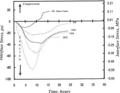
Silica Fume: Interface stress versus hydration time curves are presented for paste matrices (wlc = 0.25, 0.35) containing portland cement with up to 30% silica fume addition (figures 1 and 2). In general tensile stresses develop at the interface, reach a maximum after 6 to 11.5 hours of hydration and recover, the degree of recovery being dependent on amount of silica fume and water-cement ratio.It is suggested that processes affecting interparticle attraction and
structuration-formation of a solid network or continuum
-
contribute to the initial development of tensile stresses at the interface during the presetting period of cement paste. These stresses are higher for silica fume content >lo%.Increased hydration rate and reaction between CH and Si02 with silica fume addition may be contributing factors. Subsequently, tensile stresses continue to increase until a maximum value is reached.
Silica Fsme
-
Compression / 0 % 1 %-
... - 4 9-
5% _...._...--..-.- 15% do%-
0 5 10 15 20 25 30 35 40 Time, hoursFigurt 1. Stress at the steel-cement paste interface for cement paste containing silica fume, WIC = 0.25.
Vol. 19, No. 6 961
STRESS, INTERFACIAL, T H I N PASTE COATINGS
The additional tensile stress is likely due to internal dessication producing meniscus forces in pores which generate compressive forces in the solid. Another possible contribution to tensile stress development could arise due to mass transfer of water out of the specimen. The driving force would be the heat effects due to the hydration process, in spite of the low temperature change ( ~ 0 . 1 OC). This mechanism has not been confirmed. If operative, however, the values of stress determined by the OBM would be applicable for thin specimens only. It is noteworthy that values of bond strength for cement pastes (wlc = 0.25- 0.45) determined by the OBM compare favorably with values determined by several other methods for pastes having varying geometry and thickness. This suggests that the interface stresses determined by the OBM for thin paste coatings (c0.03 in.) may be valid for thicker coatings. Stress curves (1, 2% silica fume; wlc = 0.25 and 5, 10% silica fume; wlc = 0.35) show two distinct maximum stress peaks. The second peak at 10.5, 1 1.5, 13.5 and 12 h
respectively may be due to nucleation and growth of C-S-H or possibly ettringite to monosulphoaluminate conversion3. Two peaks at other silica fume contents possibly exist but are hidden or merged due to other stress effects. After reaching a maximum value the tensile stress decreases and recovery occurs. Swelling or compressive stresses are eventually generated in the 0 and 1% silica fume systems (wlc = 0.25) at 9.6 and 17.5 h. It is suggested that recovery may be due to more than one mechanism. Readsorption of water would cause a decrease in compressive stress of the solid due to menisci forces. This has been postulated to explain volumetric expansions associated with re-absorption
-1 00 -0.69
0 5 10 15 20 25 30 35 40 Time, hours
Figure 2. Stress at the steel-cement paste interface for cement paste containing silica fume, WIC = 0.35 .
962
J . J . Beaudoin, e t a l .
Vol. 19, No. 6
of bleed water observed during the hydration of portland cement4. It is also possible that irrecoverable strain due to irreversible deformation of the solid could limit the recovery of interfacial stress.
A tabulation of the interface stress values, 6max (maximum tensile stress), 6R (tensile stress recovery) and 6r (residual stress) is given in table 1.
TABLE 1
-
Interface Stresses in Cement-Silica Fume SystemsMaximum tensile stress; + Tensile stress recovery;
'
Residual tensile stress Silica Fume YO 0 1 2 4 5 10 15 30Maximum stress values increase with silica fume content for both wlc = 0.25 and 0.35 but are greater for w/c = 0.25. It is expected that the effects of self-
desiccation would be greater for the less permeable wlc = 0.25 paste. The tensile stress recovery, 6R, expressed as a percent of 6max is greater for wlc = 0.35. This is consistent with a water readsorption mechanism as it would be
expected that the more permeable paste system would recover to a greater I extent. Residual stress is also significantly reduced at the higher water-cement q ratio.
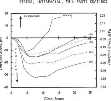
SteellCement
+
CaC03-: lnterface stress-hydration time curves are given in figure 3 for cement paste matrices containing up to 25% CaC03 addition. The curves are characteristically similar to those obtained for silica fume addition but with significantly reduced values of 6max and 6r (Table 2). Residual stress isomax. ' psi (MPa)
w k 0.25 7.5 (.05) 17.0 (. 12) 23.0 (.16) 31.0 (.21) 50.0 (.34) 68.5 (.47) 83.0 (.57) 100.0 (.69) a ~ , + psi (MPa) wlc U R , (YO maw.) w/c 0.35 10.5 (.07)
--
---
--
23.0 (.16) 36.5 (.22) 55.0 (.38) 84.0 (.58) 0.25 7.5 (.05) 17.0 ( . l a 19.5 (.13) 23.5 (.16) 29.0 (.20) 32.0 (.22) 32.0 (.22) 47.5 (.33) 0.25 100.0 100.0 85.0 76.0 58.0 47.0 39.0 47.0 'vr psi (MPa) WIC 0.35 10.5 (.072)---
--
--.---
17.5 (.12) 22.0 (.IS) 36.0 (.25) 57.0 (.39) 0.35 100.0----
---
--
81.4 57.0 65.0 68.0 0.25---
---
3.5 (.02) 7.5 (.05) 21.0 (.14) 36.5 (.25) 51.0 (.35) 52.5 (.36) 0.35 a--
--
---
4.0 (.03) 16.5 (.11) 19.0 (.18) 27.0 (.19)Vol. 19, No. 6 963
STRESS, INTERFACIAL, THIN PASTE COATINGS
40 -0.69
0 5 10 15 20 25
Time, hours
Figure 3. Stress at the steel-cement paste interface for cement paste containing
calcium carbonate, WIC = 0.35.
only significant at 20 and 25% CaC03 contents. Calcium carbonate
accelerates the hydration of cement which may account for the increase in initial tensile stress with CaC03 contents. The modified surface of the hydrating cement and nucleation on the CaC03 particles are two mechanisms that could produce this effect. Results indicate that 15% carbonate addition has the effect of increasing total porosity of the paste. This could be a factor in tensile stress recovery if readsorption of water is a relevant mechanism. The curves for 15, 20 and 25% carbonate addition exhibit a second maximum stress peak at 15, 13
964
J.J. Beaudoin, e t al.
V o l . 19, No. 6
and 11.5 h respectively. This may be a stress response due to acceleration of the ettringite to mono-sulphoaluminate conversion with CaC03 addition.
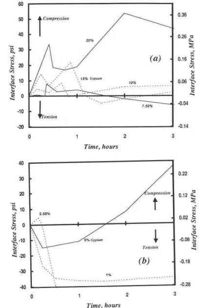
SteellC~A
+
Gvpsum: Interface stress-hydration time curves for C3A-Gypsum systems are given in figures 4, 5. The curves in figure 4 present data for the first 3 h of hydration. Curves for gypsum contents of 7.5-
20% (figure 4 (a))generally exhibit two compressive stress peaks followed by a gradual increase in compressive stress in the first four hours of hydration. At 2.5% gypsum content (figure 4 (b)) there is a single compressive stress peak in the first 10.5 min. At lower gypsum contents compressive stresses are gradually generated only after a rapid initial development of tensile stresses. The interface stress development could be explained as follows617. In the pure C3A system (w/s=0.40) forces associated with interparticle attraction, network formation and production of hexagonal hydroaluminates are responsible for generation of tensile stresses in the first 25 min. Conversion of hexagonal hydroaluminates to C3AH6 removes the former from grain surfaces and accelerates the reaction. This results in rapid generation of compressive stress governed by the rate of dissolution of C3A and the hexagonal hydroaluminates. With 2.5% gypsum addition, hexagonal hydroaluminate and a small amount of ettringite form in the first few minutes giving rise to the initial small compressive stress peak. All gypsum is consumed in about the first 30 min. Tensile stresses are generated during the first two hours due primarily to network formation and meniscus effects accompanying the initial formation of hexagonal hydroaluminates. Subsequent compressive stress is due to an increase in the amount of hexagonal hydroaluminates formed. Meniscus force effects in shaping the stress response cannot be ruled out as the hexagonal hydroaluminate network
is not impervious. At gypsum contents of 10, 15 and 20% both hexagonal hydroaluminates and ettringite are present in the first few minutes and compressive stresses at the interface are developed (first peak, figure 4 (a)). Disruption expansions that occur when ettringite is formed suggest that it cannot form an impermeable layer. Menisci formed in the pore system of this layer may
play a role in stress development. In addition, mass transfer of water out of the r
specimen due to heat effects can be a contributing factor. Thermal stresses are, 1
however, negligible as the temperature change in these experiments is insignificant (c0.1 OC). With 10, 15 and 20% gypsum a second compressive stress peak clearly emerges (0.6, 0.9 and 2.0 h). The existence of a second
stress peak parallels the development of a second peak in the conduction I
calorimetric curves of CgA-gypsum systenls8. The second peak is attributed to
V o l . 19, N o . 6
STRESS, I N T E R F A C I A L , T H I N PASTE COATINGS
1 2 Time, hours -0.28 1 2 3 Time, hours 250%
.
Tension.
. . '
I. .
' , ' ,.. .
'.
(b)
. .
1% ....-_._. ..._...____....-..-.a. ._____...' k I AFigure 4 . Stress at the steel-tricalcium aluminate paste interface for tricalcium aluminate paste containing gypsum, W/C = 0.4, 3h hydration; (a) 7.5%
-
20% gypsum, (b) 0%-
2.5% gypsum.I
expansion forces due to interlayer of the monosulfoaluminate, crystal pressures, menisci effects, pore structure change and transient heat effects. The larger peak stress at higher gypsum contents appears to be dependent on the amount of sulfoaluminate present.
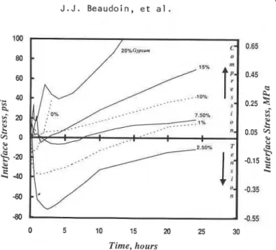
Increased compressive stress after the second peak (figure 5) reflects microstructural change and the slow rate of reaction with continual formation of both hexagonal hydroaluminates and ettringite.
966 J . J . Beaudoin, et al. V O ~ . 19, No. 6 -80 -0.55 0 5 10 15 20 25 30 Time, hours
Figure 5. Stress at the steel-tricalcium aluminate paste interface for lricalcium aluminate paste containing gypsum, WIC = 0.4, 24h hydration.
CONCLUSIONS
1. A novel technique has been developed which permits determination of
stresses at the steel-cement matrix interface for thin coatings of cement paste on steel. Stresses due to the hydration process can be determined. Stress due to hydration is not normally taken into account in conventional bond strength tests.
2. Bond strength determinations of thin cement paste coatings on steel
substrates using this technique are in reasonable agreement with bond strength values obtained from a variety of conventional bond tests. This
suggests that values obtained may not be limited in application to thin coatings.
3. The maximum interfacial stress due to hydration increases with silica fume
and calcium carbonate addition, silica fume giving the greatest stress. This is consistent with observed cracking problems associated with the use of concrete containing large amounts of silica fume.
4. The intertacial stress resulting from the CgA-gypsum reaction is
dependent on the amount of gypsum and hydration time. Both compressive and tensile stresses can be generated. Interpretation of peaks in the stress patterns provides a means of assessing the contribution of the hydrated
Vol. lg,, No. 6
STRESS, INTERFACIAL, T H I N PASTE COATINGS
aluminate phases to development of interfacial stress.
5. Several mechanisms may be responsible for development of interface stress. These include: structuration processes, hydration, nucleation, self- desiccation and menisci effects, irreversible deformation.
6. The OBM technique is a new tool that may be used for following the structuration in cement systems.
ACKNOWLEDGEMENT
The authors acknowledge the fine work of Mr. R.E. Myers in conducting the experiments.
REFERENCES
1. M. Nakayama and J. J. Beaudoin, Cem. Conc. Res.
1Z
(3), 478 (1 987).2. S.G. Croll, J. Oil and Col. Chem. Assoc.,
m,
271 (1980).3. V.M. Malhotra, V.S. Ramachandran, R.F. Feldman and P.C. Aitcin, Condensed Silica Fume in Concrete, CRC Press, pp 221 (1987).
4. J.F. Raffle, 'The Chemistry and Chemically-Related Properties of Cement', Brit. Ceram Proc. No. 35,295 (1 984).
5. V.S. Ramachandran and C. Zhang, Cement With Calcium Carbonate Additions, Seminar 2 on Cements with Mineral Additions, 8th Int. Congr. Chem. Cem., Brazil (1 986).
6. R.F. Feldman and V.S. Ramachandran, J. Amer. Cer. Soc., @ (5), 268 (1 966).
7. R.F. Feldman and V.S. Ramachandran, Mag. Conc. Res.,
a
(57), 185 (1 966).8. V.S. Ramachandran and C.M. Zhang, Mat. and Struct.,
19
(1 14), 437(1 986).
CEMENT and CONCRETE RESEARCH. Vol
.
19, pp. 968-972, 1989. P r i n t e d i n the USA. 0008-8846/89. $3.00+00. Copyright ( c ) 1989 Pergamon Press p l c .HYDRATION AND STRENGTH DEVELOPMENT OF CEMENTS PRODUCED FROM RAW MIXES CONTAINING Moo3, Nb205, WO AND Zr02
3 G . K a k a l i , V . Kasselouri and G . P a r i s s a k i s
N a t i o n a l Technical U n i v e r s i t y o f Athens, Laboratory o f Inorganic and A n a l y t i c a l Chemistry
42 P a t i s s i o n S t . Athens, Greece
(Communicated by F. ~ a s s a z z a ) ( ~ e c e i v e d March 10, 1989)
ABSTRACT
The purpose of this paper is to investigate the effects of MOOS, NbaOa, W03 and ZrOa on the hydration process and on the mechanical properties of cement. The above oxides were added separately to cement raw mixes and their influence on hydration of derived cements was studied by means of thermal analysis and X-Ray diffraction. Additionally, compressive strength and setting time were measured.
Introduction
As it is known, some transition element compounds, added either in cement raw mixes or in cement during the grinding process, strongly affect the hydration phenomena. In general, these compounds delay cementing and hardening, [1,2.31, with an exception of Cr compounds which seem to accelerate hydration.
[3.41.
The present study belongs to a series of experiments concerning the effect of transition element compounds on the formation of clinker and on the properties of cement and aiming to determine the connection between transition elementsw particularity and the way they affect clinker formation and
,
cement hydration. It has been found that MOOS and W& exert a considerable effect on sintering of cement raw mixes and clinker microstructure while Zr& causes color change of clinker, [51. In order to find out in what degree the presence of the above mentioned oxides affect the mechanical properties of cement, setting time and compressive strength in cement pastes and mortars, respectively, were measured. In addition, differential scanning calorimetry was used for the quantitative determination of Ca(OH)= and X-Ray diffraction for the study of hydration products.
This paper is being distributed in reprint form by the Institute for Research in Construction. A list of building practice and research publications available from the Institute may be obtained by writing to the Publications Section, Institute for Research in Construction, National Research Council of Canada, Ottawa, Ontario, KIA 0R6.
Ce document est disvibuB sous forme de tir6-&-part par 1'Institut de recherche en construction. On peut obtenir une liste des publications de I'Institut portant sur les techniques ou les recherches en matikre de batiment en Ccrivant

![How genetic pressure of [i]Medicago trunculata[/i] acts on the molecular selection and population pattern of its favourite symbiotic bacteria, [i]Sinorhizobium[/i] sp.?](data:image/gif;base64,R0lGODlhAQABAIAAAP///wAAACH5BAEAAAAALAAAAAABAAEAAAICRAEAOw==)