HAL Id: hal-01369224
https://hal.archives-ouvertes.fr/hal-01369224
Submitted on 20 Sep 2016
HAL is a multi-disciplinary open access
archive for the deposit and dissemination of
sci-entific research documents, whether they are
pub-lished or not. The documents may come from
teaching and research institutions in France or
abroad, or from public or private research centers.
L’archive ouverte pluridisciplinaire HAL, est
destinée au dépôt et à la diffusion de documents
scientifiques de niveau recherche, publiés ou non,
émanant des établissements d’enseignement et de
recherche français ou étrangers, des laboratoires
publics ou privés.
Outstanding magnetorheological effect based on
discontinuous shear thickening in the presence of a
superplastifier molecule
Georges Bossis, Y Grasselli, Alain Meunier, O Volkova
To cite this version:
Georges Bossis, Y Grasselli, Alain Meunier, O Volkova. Outstanding magnetorheological effect based
on discontinuous shear thickening in the presence of a superplastifier molecule. Applied Physics
Letters, American Institute of Physics, 2016, 109 (11), pp.111902-1 111902-4. �10.1063/1.4962467�.
�hal-01369224�
Outstanding magnetorheological effect based on discontinuous shear
thickening in the presence of a superplastifier molecule
G. Bossis,
1Y. Grasselli,
2A. Meunier
1and O. Volkova
11Université de Nice Sophia Antipolis, Laboratoire de Physique de la Matière Condensée, CNRS UMR 7336, Parc
Valrose, 06108 Nice cedex 2, France
2SKEMA Bachelor – 60 rue Dostoievski – BP085 – 06902 Sophia Antipolis ,France
We present experimental results showing an increase of stress of about 150kPa for a weak applied magnetic field (H<10kA/m) in an aqueous suspension of carbony iron particles coated with a superplasticizer molecule used in cement industry. These values, which are several orders of magnitude larger than those classically obtained with magnetorheological suspensions at such low field, can open the way to new applications. These high values result from the triggering of a discontinuous shear thickening induced by the magnetic field. A phase diagram is presented for a volume fraction of carbonyl iron particles of 62%, showing two domains in the plane, magnetic field versus shear rate. The lower one is liquid of quite low viscosity and the upper one corresponds to a jammed phase where the particles are in frictionnal contacts and can only move under very high stresses. The transition between the two states is monitored by the ability of the superplasticizer molecule to resist to the compression forces both hydrodynamic and magnetic.
2
Magnetorheological(MR) fluids are made of micron sized ferromagnetic particles suspended in a carrier fluid, more often a silicone oil. Under the application of magnetic field , the particles acquire a magnetic moment and attract each other to form a solid gel characterized by a yield stress τy. The rheological behavior follows approximately a Bingham law :τ = τ + η γ
y 0ɺ
where η0 is the viscosity of the suspension in the absence of the field andγ
ɺ
the shear rate. The higher the yield stress the better will be the control of the effective viscosity of the fluid. The maximum attainable depends on the magnetization saturation of the particles, on their volume fraction and, of course, on the intensity of the applied magnetic field. In practice commercial fluids are based on carbonyl iron particles, with typical yield stresses of 30-60kPa for a magnetic induction of 0.4-0.6T1,2.Many efforts have been done to improve these fluids firstly in view to increase the yield stress and secondly to improve the redispersion of particles after their sedimentation which occurs quickly due to their high density. One way is to use fibers instead of spherical particles since they are more easily magnetizable and, indeed, for the same volume fraction and the same external field the yield stress is higher3,4 , but due to entanglement the maximum possible volume fraction is lower so finally the result is not better. Concerning the aggregation due to sedimentation it can be reduced by using shell like particles where only the outside part is made of a magnetic material5,6; a simpler approach is the use of a surfactant molecule ,like for instance stearic acid and many others, which form a barrier preventing the surfaces of the particles to come in contact. On the other hand the use of a surfactant molecule can allow to increase the volume fraction of particles and then to increase the yield stress. In cement industry superplastifier molecules are currently used to increase the solid content of the cement. Nevertheless at high volume fraction we encounter the phenomenon of discontinuous shear thickening which is a jammed state where a network of percolated frictional contacts between particles is formed at a given critical shear stress7,8. In this work we use this phenomenon to induce the jamming sate at a critical shear rate which can be controlled by the magnetic field. Then, instead of a yield stress which depends only on the dipolar interactions between the particles, we add a ratcheting effect which can multiply the simple magnetic interaction. Actually this kind of effect has been observed by D.J. Klingenberg et al: they found that adding a part of non magnetizable particles to magnetizable ones could notably increase the field induced yield stress9. Although not explained at this time the authors recently prove that it was due to a jamming effect induced by the magnetic field in the presence of a higher total volume fraction of particles10. The solid
friction between particles, which can be induced by the attractive magnetic forces is also one of the cause of the enhancement of the MR effect in suspensions of magnetic fibers11 or of faceted particles12 compared with spheres at the same volume fraction.
In our experiments we have used commercial carbonyl iron particles (CIP grade HQ from BASF13) suspended in water and a commercial superplasticizer molecule (Optima 100 from Chryso) which has a head made of two phosphonate groups (PO3H-) and an hydrophilic tail made of a polyoxyethylene chain. The counter ions of the phosphonate group are sodium ions which react with the OH- group present on the surface of iron particles, contributing to form an ionic bond between the oxygen of the phosphonate and iron atoms. The use of this molecule allows to reach volume fraction of carbonyl iron in water as high as 62% with a small yield stress -about 20Pa- and still a low plastic viscosity -η0
≃
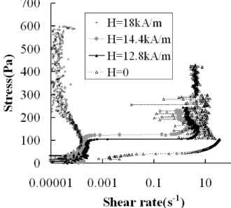
1Pa.s.The experiments were conducted firstly in the imposed shear stress mode on a MCR502 (Physica) rheometer in the plate plate geometry using a serrated plateau and a serrated plate to prevent the slipping of the suspension on the walls. A coil of inner diameter 75mm was surrounding the plate of diameter 40mm. The ramp of stress was chosen at a typical rate of 20 Pa/min which allows to obtain steady state results and is still fast enough to be able to do several successive experiments without drying. The resulting rheograms are presented in Fig.(1) for different magnetic fields and a volume fraction Φ=62%. The weight fraction of the polymer was taken equal to 0.2% of the mass of the particles which, from adsorption isotherm and a BET specific surface of 0.45m2/g, corresponds to the adsorption of one layer of the polymer
FIG. 1. Ramp of stress for a volume fraction Φ=62% and different values of the magnetic field.
The jamming transition at zero field occurs at a critical shear rate of 35s-1 and is characterized by a discontinuity in the shear rate followed by oscillations around an
3
average value which is lower than the critical one. When the field is increased the value of the critical shear rate decreases and reaches a zero value at a field of 18 kA/m. Inside the jamming domain, if we continue to increase the stress, either the average shear rate does not change and we end up by reaching the limiting torque of the apparatus ( 0.3N.m) or we have an expulsion of the suspension outside the gap. An other way to explore the effect of the magnetic field on the jamming transition is to impose a constant shear rate and then to increase progressively the field. The result is presented in Fig. 2 with a low imposed shear rate:γ =
ɺ
0.001
, so that the stress is equivalent to a yield stress. We see that the yield stress increases progressively with the field, as it should when the only interactions between the particles are dipolar ones; then above a given value, here H=18kA/m, we have a jump in the yield stress which overcomes the limit torque of the rheometer and represents an increase of two orders of magnitude in the yield stress. Such transition was also recently observed12 with a carbonyl iron suspension at Φ=30% without additive, but with an increase of stress only by a factor 2 and for much higher fields: H>500kA/mFIG 2. Evolution of the stress versus the applied field for a constant shear rate of 0.001s-1; volume fraction Φ=0.62
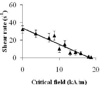
It then appears that the jamming transition can be monitored by the application of a magnetic field. For a volume fraction Φ=0.62 we have reported in Fig.3 , for a given imposed shear rate, the value of the magnetic field which gives the jamming transition. In this way we obtain a division in two domains of the plane expressing the critical field corresponding to the jamming transition versus the imposed shear rate. The lower part corresponds to the liquid state and the upper one corresponds to the jammed state. The uncertainty is given by the standard deviation of the values corresponding to different experiments at the same shear rate. The boundary between the two domains can be approximated
by a straight line. The jamming transition occurs when the stress acting on a given pair of particles is strong enough for pushing the adsorbed molecules away of the contact zone. Then we expect that this critical stress ,σc, will only depend on the shape of the particles and on the characteristics of the adsorbed polymer. In this case we can write the condition of jamming like :
c 0 c m c c m 0
1
(H) or
(
(H))
σ = η γ + τ
γ =
σ − τ
η
ɺ
ɺ
where τm(H) is the magnetic stress. If τm(H) is linear in the field, then we recover the straight line of Fig. 3. Actually the theory for the magnetic stress between carbonyl iron particles predicts rather, at low field, a H3/2 dependence14. A possible explanation for this discrepancy stands in the fact that we have ignored the angular dependence of the forces: the compressive magnetic force between two particles is maximum when their line of centre is aligned with the field whereas the hydrodynamic compression force is maximum at θ=-45° relatively to the direction of the field. As σc is the applied shear stress it does not reflect exactly the compressive one; a theoretical approach, which is beyond the scope of this paper, should take into account the angular dependence of the compressive stress. It is also worth noting that at usual volume fraction of MR fluids (e.g. Φ=45%), there is no impact of the coating by the superplastifier on the yield stress since the volume fraction is not high enough to produce the jamming transition.
FIG. .3 Critical field corresponding to the jamming transition for different constant shear rates
An important question for the practical applications, is to know what happens above the transition. In the jammed domain the compressive force which is both due to the hydrodynamic stress and to the magnetic stress, is large enough to sweep the polymer out of the contact surface and to provoke the solid friction between the particles
4
which is at the origin of the jamming phenomenon. When the total stress is reduced, either by decreasing the shear rate or the magnetic field , the polyelectrolyte molecule can come back between the surfaces of the particles and the suspension can flow again. At this stage it is difficult to know if the suspension can still flow in the jamming sate if a strong enough stress was applied because, on one hand, the torque range of the rheometer is too low and, on the other hand, the radial stress which is developped during the jamming is strong enough to expel the particles from the suspension as explained by Cates et al 15. We have developped a home made viscosimeter based on a commercial one (CAD company) which can afford and measure torques as high as 10N.m which is about fifty times the maximum torque of commercial rheometers. We have also designed an hermetic cell in which the suspension is confined by a teflon seal. The outer cylinder is in plexiglass so we can check the absence of bubbles inside the cell and it is serrated with stripes parallel to the axis of rotation to prevent wall slip. The tool is made of a double helix which is used to study the rheology of complex fluid16; this tool behaves approximately like a cylinder of same radius but it has the advantage to induce a small flow along the axis of the helix which contributes to avoid sedimentation or segregation effects. Its diameter was 22mm and the gap between the outer cylinder and the helix was 2mmIt is worth noting that, in this configuration, the field inside the cell is larger than between the plates for the same external field due to the difference in demagnetizing field. In these experiments we have a mechanical safeguard which disconnects the cell from the motor at a torque around 8N.m. A typical result obtained with the helicoidal tool is shown in Fig.4 for a constant applied shear rate of 11s-1 . The field was increased progressively from zero with a step of 0.48kA/m every 5s
Fig.4 Stress versus time during a ramp of field with a step of 0.48 kA/m every 5s; the shear rate was constant and equal to 11 s-1
We see that we have a first jump of stress up to 50kPa at a field H=6.7 kA/m , and then each time the field is increased we have an important increase of stress. Here we stopped the field at H=8.2 kA/m to avoid the triggering of the torque limiter and we end up with a steady value of 150kPa, then the field is turned off after
30s and the stress immediately comes back to its low initial value. This value of 150kPa is approximately three times more than the maximum yield stress in conventional MR fluids and ,above all, it is obtained at a very low field (H=8kA/m) compared to the one used with conventional MR fluids (typically 300-400kA/m for a stress of 40-50 kPa). It is important to note that we have a steady state in the jamming regime whose stress is controlable by the magnetic field.
The vane geometry also avoids slipping of the suspension on the walls. We have made one with six blades , an external diameter of 22mm and a length of 43mm. With a vane as well as with a cylinder the sedimentation of the particles can change locally the volume fraction and also produces irreversible aggregation. The fact to use an horizontal geometry is less problematic for the redispersion of the particles, nevertheless the effect of sedimentation is still an opened question not easy to solve experimentally. We have used the opportunity of parabolic flight offered by the CNES to check this effect. The duration of a parabola is 22 s. In the experiment presented in Fig.5 the field was turned on before the parabola and a ramp of shear rate started 7s before the microgravity and reached its maximum of 20 s-1 after 15s. The same experiment was repeated just after in normal gravity. We see in fig. 5 that there is a difference at short time when the rotation of the tool has still not completely redispersed the suspension, but that after a few seconds there is no noticeable difference. This is a proof that the horizontal geometry is very efficient against sedimentation. We note also that, here too, we reach a stationary very high stress ,as with the helix tool, but for a field which is more than two times larger. We have no simple explanation for this difference.
Fig.5 Stress versus time with vane geometry at a field H=19.2kA/m; comparison microgravity/gravity
In summary, using a superplastifier molecule with carbonyl iron particles dispersed in water, we found a discontinuous shear thickening with a huge jump of stress which can be controled by a low magnetic field. For instance at H=10kA/m the Bingham number:Bi= τ η γy/ 0ɺ ,with τy=150kPa and η0=1Pa.s, is always larger than 102 even for shear rates as high as 104 s-1 , meaning that we have a very large range of control of
5
the effective viscosity. In the case of applications related to the locking of rotating parts, like for brakes or clutches, it is important that the jammed state remains stable for a long enough time which seems to be the case as observed in figs 4 and 5 but it needs to be confirmed more systematically. This opens the way to the synthesis of new MR fluids which will be more efficient than the usual ones at much lower fields, so allowing new applications. Furthermore, as the magnetic force induced by the field can be easily estimated, it gives a new approach for a better understanding of the DST phenomenon.Acknowledgments
This work was supported by the Centre National d'Etudes Spatiales CNES and by European Spatial Agency ESA
.
References1 http://www.lord.com/sites/default/files/DS7015_MRF-132DGMRFluid.pdf
2
R.F.Ierardi, A.J.F Bombard, Journal of Physics: Conference Series 149 , 012037,(2009)
3
R.C. Bell, J.O. Karli, A.N. Vavreck, D.T. Zimmerman, G.T. Ngatu and N.M.Wereley, Smart Mater. Struct. 17 015028 (2008)
4G.Bossis, J.Alves-Marins, P.Kuzhir, O.Volkova, A.Zubarev,J. Intell. Mat. Syst. Struct. 26, 1871 (2015)
5
B.J. Park, F.F. Fang and H.J. Choi, Soft Matter,6, 5246(2010)
6X.Zhang, L.Liu, Y.Qi, Z.Liu, J.Shi, W.Wen, Appl. Phys. Lett. 88, 134107 (2006)
7W.J. Frith., P. d'Haene, R. Buscall, and J. Mewis, J.Rheol. 40, 531-548 (1996).
8
R.Mari, R. Seto, J. F. Morris,and M.M. Denn, J. Rheol.
58, 1693–1724 (2014)
9J.C. Ulicny, K.S.Snavely, M.A.Golden, and D.J. Klingenberg , Appl. Phys..Lett., 96, 231903 (2010).
10D.J.Klingenberg, communication at ERMR2016 , Incheon, Korea July 4-8, 2016
11M.T.Lopez-Lopez, P.Kuzhir, and G.Bossis, J. Rheol. 53, 115 (2009); 53,127(2009)
12 F. Vereda,
J. P. Segovia- Gutiérrez, J. de Vicente,
and R. Hidalgo-Alvarez, Appl. Phys. Lett., 108, 211904
(2016)
13http://www.monomers.basf.com/cm/internet/en/function/conve
rsions:/publish/content/Produkte/Metallsysteme/CIP/CIP_Gener al_PO_e.pdf
14J.M.Ginder, L.C.Davis and L.Elie, Int.J.Mod.Phys.B 10, 3293(1996)
15M.E. Cates, M.D. Haw and C.B. Holmes, J. Phys.: Condens. Matter 17 , S2517(2005)
16A. Aït-Kadi A., P. Marchal , L. Choplin, A. S.
Chrissemant and M. Bousmina, The Canadian Journal of Chemical Engineering, 80, 1166,(2002)