HAL Id: cea-02439454
https://hal-cea.archives-ouvertes.fr/cea-02439454
Submitted on 26 Feb 2020HAL is a multi-disciplinary open access
archive for the deposit and dissemination of sci-entific research documents, whether they are pub-lished or not. The documents may come from teaching and research institutions in France or abroad, or from public or private research centers.
L’archive ouverte pluridisciplinaire HAL, est destinée au dépôt et à la diffusion de documents scientifiques de niveau recherche, publiés ou non, émanant des établissements d’enseignement et de recherche français ou étrangers, des laboratoires publics ou privés.
Based on Bottom-Flooding through Porous Concrete
O. Yilmaz, G. Pohlner, M. Buck, J. Starflinger, C. Journeau
To cite this version:
O. Yilmaz, G. Pohlner, M. Buck, J. Starflinger, C. Journeau. Design Considerations for a Core-Catcher Concept Based on Bottom-Flooding through Porous Concrete. NUTHOS11 - 11th International Top-ical Meeting on Nuclear Thermal Hydraulics, Operations and Safety, Oct 2016, Gyeongju, South Korea. �cea-02439454�
1/11
Design Considerations for a Core-Catcher Concept Based on
Bottom-Flooding through Porous Concrete
Ö. Yilmaz*, G. Pohlner, M. Buck and J. Starflinger
Institute of Nuclear Technology and Energy Systems (IKE), University of Stuttgart Pfaffenwaldring 31, 70569 Stuttgart, Germany
[email protected], [email protected], [email protected], [email protected]
C. Journeau
CEA Cadarache13108 St Paul lez Durance, France [email protected]
ABSTRACT
In case of a severe accident in a light water reactor, core melt can be released from the reactor pressure vessel and dislocate to reactor cavity where it attacks the concrete structures. In order to avoid possible containment failure due to molten corium concrete interaction, the molten corium is to be retained and cooled. Core-catcher concepts considering water-injection via the bottom into the melt layer can lead to rapid quenching and solidification of the melt layer, forming a highly porous structure. A design variant of the comet concept relies on porous concrete layers to distribute the water below the melt layer. This paper presents a methodology that was developed to determine major design parameters for a bottom cooling concept with porous concrete structure considering a scale dimensioning of a generic pressurized water reactor of Gen II. Design parameters were systematically varied in order to calculate the optimum concrete configuration in view of porosity and permeability. Using the COCOMO3D code (COrium COolability MOdel, 3Dimensional), which is being developed at IKE, simulations were carried out both in 2D and 3D for symmetrical and non-symmetrical water inlet flow configurations. The results show that sufficient water flow rates can be reached in order to cool the molten corium, which is promising for the applicability of this concept as an accident mitigation device for existing and new reactors.
KEYWORDS
CORIUM COOLABILITY, BOTTOM FLOODING, REACTOR SAFETY
1. INTRODUCTION
In case of a severe accident in a light water reactor (LWR) with core melting, melt may be released from the reactor pressure vessel (RPV) and dislocate into the reactor cavity where it attacks the concrete structures. If the core melt cannot sufficiently be cooled to stop the molten corium concrete interaction (MCCI), the containment may be attacked and fail, causing subsequent release of fission products into the environment. After many years of experimental and analytical studies (e.g. the OECD-MCCI project) [1] it has not yet been proven that top-flooding of the melt can stop the MCCI in due time for all configurations. New reactor designs of Gen III+ (e.g. EPR, ESBWR) address this issue through core catchers which aim at confining the core melt within dedicated structures that are cooled along their boundaries in order to keep them intact [2]. For existing reactors such solutions are however not feasible, mostly already due to lack of space. An alternative to these is the concept of water injection via the bottom of the melt layer (COMET concept) [3]. The water percolating the melt from below leads to rapid quenching and solidification, resulting in the formation of a highly porous
2/11
structure. A design variant of the COMET concept (COMET-PC) relies on porous concrete layers to distribute the water below the melt layer. It is technically relatively simple to install for new constructed nuclear power plants and it could be even suited for back-fitting of existing plants since it does not require much space.
The aim of the work described in this paper is the determination of major design parameters and required properties for a bottom cooling concept using a structure of two porous concrete layers considering the scale dimensions of a generic pressurized water reactor (PWR) of Gen II. The two concrete layers are located at the bottom of the reactor cavity, the lower layer being more porous than the upper layer. Water is fed from the side into the lower porous concrete layer. The cooling water flow rates of approx. 1 mm/s are necessary to quench and remove the residual heat from the corium in reasonable time and are estimated from results of COMET experiments performed at KIT [4]. The design goal is to achieve this flow rate over the whole surface of the melt, with variations as small as possible, through variation of dimensions and hydraulic properties of the porous concrete layers. A feasible range of porous concrete properties was determined from a literature survey. Then, the COCOMO3D code, which is being developed at IKE, was used to calculate the flow inside the porous concrete for different design properties of the concrete layers in order to determine the optimum configurations. Simulations were carried out both in 2D and 3D for symmetric and non-symmetric water inlet configurations.
2. DESIGN OUTLINE AND TECHNICAL SPECIFICATIONS OF THE CONCEPT
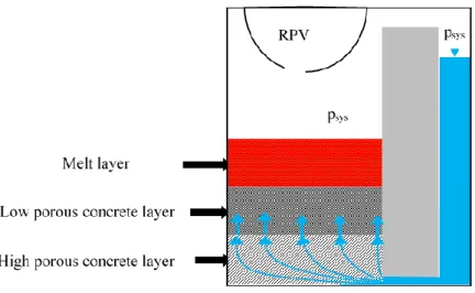
The core-catcher concept for bottom-flooding consists of two porous concrete layers at the bottom of the reactor cavity, as can be seen in Fig. 1. It is covered by a sacrificial concreate layer, ensuring leaktightness before corium arrival. This layer is considered in this work to have already been ablated. Water is fed from the side into the lower concrete layer that has high porosity, hence a high water permeability to distribute the coolant water horizontally along the reactor cavity under small lateral pressure losses. For favorable distribution of the coolant, the upper concrete layer is foreseen to be less permeable than the lower one and the permeability value is adjusted to yield an appropriate water flow into the melt.Fig. 1: Design sketch of the bottom-flooding core-catcher concept.
Coolant water is driven towards the porous concrete passively by hydrostatic pressure of the coolant water column. The hydrostatic pressure of the water should be high enough to overcome the hydrostatic pressure caused by accumulated molten corium layer on top of the concrete so that water can insert the melt layer. Pressure balance is described as in following equations:
3/11
𝑃𝑤𝑎𝑡𝑒𝑟 𝑖𝑛𝑙𝑒𝑡 = 𝑃𝑠𝑦𝑠𝑡𝑒𝑚 + 𝑃ℎ𝑦𝑑𝑟𝑜𝑠𝑡𝑎𝑡𝑖𝑐,𝑤𝑎𝑡𝑒𝑟 (1)
𝑃𝑡𝑜𝑝 = 𝑃𝑠𝑦𝑠𝑡𝑒𝑚 + 𝑃ℎ𝑦𝑑𝑟𝑜𝑠𝑡𝑎𝑡𝑖𝑐,𝑚𝑒𝑙𝑡 (2)
∆𝑃 = 𝑃𝑤𝑎𝑡𝑒𝑟 𝑖𝑛𝑙𝑒𝑡 − 𝑃𝑡𝑜𝑝 (3)
with the coolant pressure at the entrance of bottom concrete layer, Pwater inlet, the containment pressure Psystem, the hydrostatic pressure of the water column, Phydrostatic,water, the pressure at the upper surface of the top concrete layer, Ptop, the hydrostatic pressure of the accumulated melt layer, Phydrostatic,melt, and the over pressure of the coolant water that causes passive injection of the water into the melt layer ∆P.
Dimensions of the device were assumed according to the available space in reactor cavity of a generic PWR of Gen II. When instrumentations below the reactor pressure vessel and a sacrificial layer for conditioning of the melt are taken into account, it is clear that there should be a limit for the total thickness of the concrete layers. For the first calculations dimensions of the device were taken as seen in Table 1. Other design parameters, e.g. concrete permeability, water inlet configuration were varied for this geometry.
Table 1: Dimensioning of the device for first calculations.
Diameter 7.8 m
Total height 0.17 m
Height of the top layer 0.085 m Height of the lower layer 0.085 m
Cooling water can be fed to the device in various ways. In this work, first considered configuration will be to provide cooling water circumferentially around the bottom concrete layer. However, to decrease the complexity, one and three inlet points were also investigated respectively, see Fig. 2.
Fig. 2: Cooling water inlet configurations and water inlet area provided. The inlet height to the lower porous concrete layer is in any case 3 cm. In the channel case with three inlets the channel
side walls and top surface is also counted as inlet area. circumferential inlet
𝑖𝑛𝑙𝑒𝑡 =
1 inlet, opening 6°
𝑖𝑛𝑙𝑒𝑡=
3 inlets, each opening 6°
𝑖𝑛𝑙𝑒𝑡 =
3 inlets, each opening 6° inward channel length 1.2 m
4/11
2.1. Design Target
Previous COMET experiments [4] have demonstrated that 1-2 kg/(m2s) water mass flow rate of water per unit base-mat area is required to quench and solidify the melt within a reasonable time. This reasonable time on one side is fast enough to prevent base-mat penetration by melt and on the other side not too quick to trigger containment failure due to over-pressurization caused by too fast evaporation. For a typical corium melt with density of 𝜌𝑐𝑜𝑟 =3000 kg/m³ and a layer height of ℎ𝑐𝑜𝑟=0.5 meter, the decay heat rate 𝑃𝑑𝑒𝑐𝑎𝑦 = 250 W/kg and specific sensible heat 𝐻𝑐𝑜𝑟=1.5 MJ/kg can be assumed. Here, if the reasonable time span is assumed to be Δt=1200 seconds, the required water volume flow rate per unit area in order to remove the total heat from the melt layer can be calculated from the following equation:
𝑣𝑤𝑎𝑡𝑒𝑟= (𝑃𝑑𝑒𝑐𝑎𝑦+∆𝐻𝑐𝑜𝑟 ∆𝑡 ) ∙
ℎ𝑐𝑜𝑟∙ 𝜌𝑐𝑜𝑟
∆𝐻𝑒𝑣𝑎𝑝∙ 𝜌𝑤𝑎𝑡𝑒𝑟 (4)
This yields an axial superficial water velocity of 1.1 mm/s. This is the needed superficial water velocity at the upper concrete-melt contact surface, with variations as small as possible, to remove melt overheat and decay heat in reasonable time. This superficial water velocity will be the design target for this work.
3. SIMULATIONS
COCOMO3D code was applied in systematic variation calculations for optimum selection of permeability of both concrete layers, the over pressure of the coolant water and water inlet configuration. The geometry of the device was characterized as given in Section 2 for all calculation cases. As an input, the defined geometry, various permeability and over pressure values are given. Then the code calculates the axial superficial water velocity on the contact surface of upper concrete layer and melt, and its distribution. The calculated velocity is compared with design target in order to observe the influence of the parameters.
3.1. Optimization of the Permeability Values for concrete Layers
A system of layers of porous concrete, which is a special type of concrete with interconnected pores, is foreseen to transmit the water from below into the melt layer as desired. Few of the porous concrete (PC) types that can be found in literature [5], e.g. Table 2, were used as a starting point for the evaluations done in this work.
Table 2: Examples to porous concrete permeability from literature [5].
Concrete Type Permeability [m²]
PC1 1.46E-09
PC8 1.75E-09
PC20 2.25E-09
For the first calculations, PC 20 was assumed as the lower concrete layer as it has a rather high permeability. This was paired with a lower permeability of the upper concrete layer of 2.189x10⁻¹¹ m². This first case simulation was done under the assumption of a circumferential water inlet with 1.2 bar overpressure. The simulation results can be seen in Fig. 3.
Fig. 3 shows the cross section of the core-catcher device. The horizontal axis indicates the radius which is reflected symmetrically and the vertical axis indicates the height of the system of concrete layers, which was assumed to be 17 cm, with a height of 8.5 cm for each layer of porous concrete. On the right side the pressure distribution in the concrete layers is shown and on the left side of the figure, the permeabilities of the two different concrete layers (upper one blue and lower one red) can be seen.
5/11
The arrows are representing the superficial water velocity. It can be clearly seen, that the lateral velocity distribution of the coolant is strongly inhomogeneous. Nearly all water flows upwards in the outer region which leads to a higher water volume flow compared to the design target. The high pressure difference observed on the right side of the figure also indicates the high deviation of the superficial water velocity. The uppermost surface of the figure, which is highlighted by a blue arrow, is the upper concrete-melt contact surface. Lateral distribution of superficial water velocity on axial direction for this surface is shown in Fig. 4 for better understanding.
As a result, as can be seen on Fig. 4, this case yields by far too high inhomogeneous water superficial velocities at the porous concrete-melt interface, which is 3.13x10⁻² m/s on the outermost surface and 3.28x10⁻³ m/s in the center.
Fig. 3: COCOMO3D simulation results with strongly non-uniform water velocity distribution. Left: Superficial water velocities (white arrows) and permeabilities of the two layers, Right:
Pressure distribution.
Fig. 4: Lateral distribution of superficial water velocity on the porous concrete-melt contact
0,00E+00 5,00E-03 1,00E-02 1,50E-02 2,00E-02 2,50E-02 3,00E-02 3,50E-02 0 0,5 1 1,5 2 2,5 3 3,5 Su perf icia l Velo cit y ( m /s ) Radius (m)
6/11
surface for strongly non-uniform water velocity distribution case.
In order to improve the water distribution, permeability of the upper concrete layer was varied while all the other parameters were kept constant until homogeneity is reached for superficial water velocity in lateral direction. For 10% deviation from homogeneity it was observed that the required upper layer permeability is 6.49x10⁻¹³ m2 to pair with lower layer PC20. The simulation results for these concretes can be seen in Fig. 5.
Fig. 5: COCOMO3D simulation results for a uniform water velocity distribution with a deviation of 10%. Left: Superficial water velocities (white arrows) and permeabilities of the two
layers, Right: Pressure distribution.
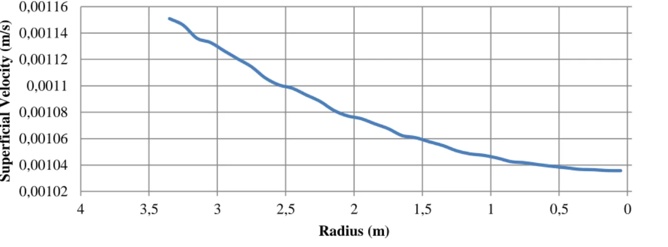
Fig. 6: Lateral distribution of superficial water velocity on the porous concrete-melt contact surface with 10% deviation from uniform distribution of superficial water velocity.
In Fig. 5, with 10% deviation from uniform distribution of superficial water velocity, it can be seen that the pressure drop along the porous concrete layers is quite low.
0,00102 0,00104 0,00106 0,00108 0,0011 0,00112 0,00114 0,00116 0 0,5 1 1,5 2 2,5 3 3,5 4 Su perf icia l Velo cit y ( m /s ) Radius (m)
7/11
Fig. 6 shows lateral distribution of superficial water velocity on axial direction for the upper concrete-melt contact surface, which is highlighted by blue arrow on Fig. 5. The result for this case yields superficial water velocity on the outermost region of 1.15x10⁻³ m/s and 1.04x10⁻³ m/s in the central region. These velocities are close to the design target and do not vary highly along the lateral direction, which may provide ideal retention and cooling potential for the melt layer.
In order to observe the results with more uniformly distributed superficial water velocity, the permeability of the upper layer was further decreased while the bottom concrete layer was kept constant. It was observed that when upper layer has a permeability of 3.12x10⁻¹³ m2, the maximum and the minimum superficial water velocities are calculated as 5.71x10⁻⁴ m/s and 5.43x10⁻⁴ m/s respectively. This means quite a uniform distribution with only 5% deviation. However, these velocities are quite below the design target which means insufficient for complete cooling of the melt. To support the optimization of the concrete selection for both upper and lower layer, a large number of variations for permeability of both concrete layers were simulated with the same geometry and overpressure. Fig. 7 shows the permeability of upper and lower concrete pairs that give the most uniform superficial water velocity distribution on the contact surface of upper concrete layer and melt.
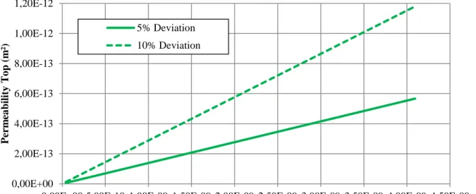
Fig. 7: Permeability of the concrete layers that gives uniform superficial water velocity distribution on upper surface of concrete layers, in lateral direction.
Superficial water velocity variations that were simulated using concrete layers yielding an ideal water distribution can be seen in Fig. 8.
The green line on Fig. 8 represents the design target. The permeability of the bottom concrete layer is seen on the x-coordinate and the permeability of the top concrete layer was selected according to the Fig. 7 for 5% and for 10% deviation of superficial water velocity. As can be seen in Fig. 8, the required water velocity value can be reached uniformly by proper porous concrete selection.
0,00E+00 2,00E-13 4,00E-13 6,00E-13 8,00E-13 1,00E-12 1,20E-12
0,00E+00 5,00E-10 1,00E-09 1,50E-09 2,00E-09 2,50E-09 3,00E-09 3,50E-09 4,00E-09 4,50E-09
P er m ea bil it y T o p ( m ²) Permeability Bottom (m²) 5% Deviation 10% Deviation
8/11
Fig. 8: Correlation of superficial liquid velocity to bottom layer permeability at constant pressure difference.
3.2. Influence of the Overpressure
Influence of the water overpressure on water velocity has also been investigated in this work. The evaluation was done for four different concrete pairs that can be seen on Table 3. Concrete layers were paired according to the Fig. 7 to yield 5% deviation in flow uniformity. For each concrete pair the over pressure was varied between 1 bar and 5 bar. The change in maximum and minimum superficial water velocity can be observed in Fig. 9. The targeted water velocity for design is shown again by green line on the figure.
Table 3: Concrete pairs for overpressure evaluation.
Concrete Permeability of Upper Layer [m2] Permeability of Lower Layer [m2]
Concrete Pair 1 1.18E-13 8.52E-10
Concrete Pair 2 2.30E-13 1.66E-09
Concrete Pair 3 3.80E-13 2.74E-09
Concrete Pair 4 5.67E-13 4.09E-09
0,00E+00 5,00E-04 1,00E-03 1,50E-03 2,00E-03 2,50E-03
0,00E+00 5,00E-10 1,00E-09 1,50E-09 2,00E-09 2,50E-09 3,00E-09 3,50E-09 4,00E-09
Su perf icia l Velo cit y ( m /s ) Permeability Bottom
Max. Velocity for 5% Deviation Max. Velocity for 10% Deviation Min. Velocity for 5% Deviation Min. Velocit for 10% Deviation
9/11
Fig. 9: Correlation of superficial water velocity to overpressure of water, for various concrete permeabilities.
For concretes that are relatively low permeable, high overpressure values should be applied in order to reach sufficient water velocities towards the melt layer. However, such high pressures may not be feasible in reactor conditions. In order to reach desired water flow rates with low overpressures, the permeability of the concrete layers should be kept accordingly high. For better understanding, Fig. 10 shows the relation between lower concrete layer permeability and the overpressure of water in order to reach 1 mm/s superficial water velocity on concrete-melt contact surface.
Fig. 10: Overpressure of water relation with bottom concrete layer permeability, in order to reach 1 mm/s superficial velocity.
3.3. Various Coolant Water Inlet Configurations
With COCOMO3D, non-symmetrical 3D configurations were also modelled and calculated. In this work COCOMO3D is used to simulate different inlet configurations of water to the concrete, besides the circumferential water feed. Especially for reactor scale proportions it is essential to analyze the
0,00E+00 5,00E-04 1,00E-03 1,50E-03 2,00E-03 2,50E-03 3,00E-03 3,50E-03 4,00E-03
1,00E+00 1,50E+00 2,00E+00 2,50E+00 3,00E+00 3,50E+00 4,00E+00 4,50E+00 5,00E+00
Su perf icia l Velo cit y Pressure Difference
Concrete 1-Max. Vel. Concrete 1- Min. Vel.
Concrete 2-Max.Vel Concrete 2-Min. Vel.
Concrete 3-Max.Vel. Concrete 3-Min.Vel.
Concrete 4 -Max. Vel. Concrete 4 -Min. Vel.
y = 0.0601x-1.013 0 1 2 3 4 5 6 7
0 5E-10 1E-09 1,5E-09 2E-09 2,5E-09 3E-09 3,5E-09 4E-09 4,5E-09
O v er press ure ( ba r) Permeability (m2)
10/11
behavior of water fed through different inlet zones, since with large diameters it is possible to face too high pressure losses over larger distances after providing the coolant.
For simulations, core-catcher geometry was taken as described in Section 2 and the overpressure was set to 1.2 bars. Permeability of bottom concrete layer and top concrete layer was set to 2.47x10⁻⁹ m2 and 7.13x10⁻¹³ m2 respectively. COCOMO3D results of single and three point inlet cases can be seen in Fig. 11. The figures illustrate the top view of the core-catcher device with distribution of superficial water velocity in axial direction.
Fig. 11: COCOMO3D results for superficial water velocity distribution for the case of single inlet with opening of 6° and height of 3 cm (left) and three inlets of same dimension (right).
For a single inlet point, the velocity value varies between 0.04 mm/s - 0.4 mm/s. For three inlet points, water velocity value between 0.1-0.4 mm/s is obtained. Both results indicate insufficient water velocity compared to design criteria. These two configurations provide rather limited water inlet areas (see Fig. 2) which causes high pressure drop along the flow path through the porous concrete, consequently yielding low water velocities on the top surface. A solution to that issue foresees the implementation of channels towards the cavity center from the outer inlet boundaries. three inlets with channels provide rather high water inlet area as can be seen from Fig. 2. Simulation results for such configuration can be seen in Fig. 12. Concrete properties and overpressure were kept as in the previous simulation.
Fig. 12: COCOMO3D results for superficial water velocity distribution for the case of three water inlet channels.
With higher water inlet area provided by inlet channels, superficial water velocity on top of the upper concrete layer varies between 0.9 mm/s – 1.3 mm/s. Compared to the design target, this can be seen as a reasonable and satisfying result concerning the distribution of the water below the melt layer.
11/11
3. CONCLUSION
Core-catcher concepts based on water injection to the melt layer in the reactor cavity from bottom can provide fast quenching and solidification, and long term cooling of the molten corium. A variety of this concept provides water to the melt layer via a system of porous concrete layers installed on the base-mat. In this paper, a number of design parameters for a bottom-flooding core-catcher concept with porous concrete were evaluated to demonstrate the applicability of the concept to generic PWR Gen II reactors. A wide range of permeability values for porous concrete layers was simulated with COCOMO3D code. Based on these simulations, adequate permeability ranges that distribute cooling water uniformly and with a sufficient flow rate along the melt-concrete contact surface were obtained. The correlation of the permeability values of concrete layers with each other and to the coolant water velocity was also presented in this work in order to support the design variations and applicability of the concept.
Overpressure that drives the coolant passively into the melt layer was varied and its influence on the resulting superficial water velocity was presented. Bringing this influence together with different permeabilities for concrete, can be a guide for optimization of the device in order to reach desired water flow rates. With 3D simulations, cooling water feed from single and multiple inlet points were evaluated. It was observed that sufficient cooling water flow rates can be provided along the cavity with adding channels to the multiple inlets.
The results show that sufficient water flow rates can be reached in order to cool the molten corium, which is promising for the applicability of this concept as an accident mitigation device for existing and new reactors. Presented graphs, from Fig. 7 to Fig. 10, can be beneficial for adjusting the design of such a core catcher concept.
ACKNOWLEDGMENTS
This work has been performed with the financial help of the French government through the “Programme d’Investissement d’Avenir” under convention number ANR-11-RSNR-0014.
REFERENCES
1. M.T. Farmer, S. Lomperski, S. Basu, “Results of reactor materials experiments investigating 2d core-concrete interaction and debris coolability,” Proceedings of ICAPP’04, International
congress on Advances in Nuclear Power Plants, Pittsburgh, PA, USA, 13-17 June (2004).
2. M. Fischer, “Main conceptual features of the EPR melt retention concept,” Proceedings of OECD
Workshop on Ex-Vessel Debris Coolability, Karlsruhe, Germany, 15-18 November (1999).
3. H. Alsmeyer, W. Tromm, “The COMET concept for cooling core melts: evaluation of the experimental studies and use in the EPR, Report FZKA 6186, EXV-CSC(99)-D036, Forschungszentrum Karlsruhe, Germany, October (1999).
4. W. Widmann, M. Bürger, G. Lohnert, H. Alsmeyer, W. Tromm, “Experimental and theoretical investigations on the COMET concept for ex-vessel core melt retention,” Nuclear Engineering
and Design 236, pp. 2304-2327 (2006).
5. A. Ibrahim, E. Mahmoud, M. Yamin, V.C. Patibandla, “Experimental study on Portland cement pervious concrete mechanical and hydrological properties,” Construction and Building Materials