APPLYING "DESIGN FOR DISASSEMBLY"
TO CONNECTION DESIGN IN STEEL STRUCTURES
by MASSACHI
OFT Scott A. Silverstein
JUL
B.S., Civil and Environmental EngineeringCornell University, 2008
LIE
Submitted to the Department of Civil and Environmental Engineering in partial fulfillment of the requirements for the degree of
MASTER OF ENGINEERING IN CIVIL AND ENVIRONMENTAL ENGINEERING at the
MASSACHUSETTS INSTITUTE OF TECHNOLOGY JUNE 2009
© 2009 Scott A. Silverstein. All rights reserved.
The author hereby grants to MIT permission to reproduce and to distribute publicly paper and electronic copies of this thesis document in whole or in part
in any medium now known or hereafter created.
/ Signature of Author: Department of Civi Certified by: Professor of Civil Scott A. Silverstein 1 and Environmental Engineering May 15, 2009
Jerome J. Connor l and Environmental Engineering Thesis Sunervisor
Accepted by:
Daniele Veneziano Chairman, Departmental Committee for Graduate Students
USETTS INSTITUTE
ECHNOLOGY
10
2009
IRARIES
APPLYING "DESIGN FOR DISASSEMBLY"
TO CONNECTION DESIGN IN STEEL STRUCTURES
by
Scott A. Silverstein
B.S., Civil and Environmental Engineering Cornell University, 2008
Submitted to the Department of Civil and Environmental Engineering on May 15, 2009 in partial fulfillment of the requirements for the degree of Master of Engineering in Civil and
Environmental Engineering at the Massachusetts Institute of Technology.
Abstract
Design for Disassembly (DfD), also known as Design for Deconstruction, is an emerging initiative of sustainable construction that favors disassembly over demolition, considering a building's full life cycle during the design phase to maximize the materials that can eventually be salvaged for reuse and thereby closing the materials loop. The author focuses on steel-frame buildings, which are among the best candidates for reuse because of the versatility and durability of individual steel members. An outline of the major principles of DfD singles out successful connection design as one of the most important factors in making a building, particularly a steel-frame building, easy to disassemble. Connection design under traditional construction methods may be optimized for disassembly through tactics such as careful allocation of bolts and welds, proper orientation of moment connections when required, and avoidance of connection details that demand coping of members. Structural engineers should also advance DfD by exploring innovations in connection design, such as standardized systems of components and clamped friction connections.
Thesis Supervisor: Jerome J. Connor
Acknowledgements
I thank Professor Jerome J. Connor for boiling the complexities of structural design down to the simplest terms possible. Your big-picture approach, coupled with your undying enthusiasm for teaching this subject, has advanced the skills and intuition of thousands of students over a
lifelong career. I am fortunate to now count myself among them.
I thank Simon LaFlamme for scheduling progress meetings and setting deadlines throughout the year. Though we cursed your demands to no end (and more often than not found ways around them), they succeeding in generating a steady motivation without which this thesis would not have been completed.
I thank Professor John Ochsendorf for teaching a superb course at MIT, 1.819 Design for Sustainability, which alerted me to the urgency of reforming building practices and taught me how a structural engineer could contribute. I also thank Mark Webster for his work in the field of Design for Disassembly and his help in finding me source material.
I thank Aimee, Derek, Sara, Gianna, Lisa, Lauren, FX, Eugene, Ellen, Laura, Sabrina, Lana, Safia, Luis, Margret, Kate, Vicky, Clair, Nate, JP, Jess, Cory, Cameron, Alice, Jessica, Carolyn, Zheng, Marie, Mahua, Kristen, Hunter, Rob, Isabel, Flavia, St6phane, Rose, and Dave for countless late nights in Room 1-143, assistance on the hardest problem sets, dinners out, potlucks, barbeques, game nights, visits to Fenway Park and Symphony Hall, karaoke, soccer, basketball, volleyball, softball, skiing, football in the snow, chocolate-covered strawberries, Burrito Wednesdays, teaching me about life all over the world, teaching me about myself, and recharging my passion for structural engineering whenever I was down.
I thank my brother, Brett, for making me laugh and for convincing me, on a personal level, that sustainability is a worthwhile pursuit.
Finally, I thank my parents for their endless capacity to give advice and positive energy. You got me hooked on engineering in the first place, and you have supported me throughout my education. I love you!
Table of Contents
Abstract 2 Acknowledgements . . . 3 Table of Contents . 4 List of Figures. 5 List of Table . 5 1. Introduction . . . 6 2. Literature Review.. . 82.1. Overview of Design for Disassembly 8
2.2. TheCase for Steel . . . 10
3. Connection Classification. . . . 11
4. Optimal Connection Design Using Traditional Methods. 14
4.1. Welds, Dowel Bolts, and High-Strength Friction Grip Bolts 14
4.2. Shear Connections .. . 17
4.3. Moment Connections . 20
5. Innovations in Connection Design 23
5.1. Standardized Systems 23
5.2. Clamped Friction Connections 24
6. Conclusion 28
List of Figures
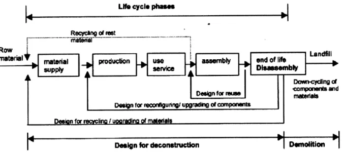
Figure 1: Design for Disassembly and the Materials Loop . 6
Figure 2: Connection Schematics . 11
Figure 3: Filled Connection - Welded Steel . . . 11
Figure 4: Interlocking Integral Connection - Lego Bricks 12 Figure 5: Overlapping Integral Connection - Rivets . 12 Figure 6: Internal-Type Accessory Connection - Bolts 12 Figure 7: External-Type Accessory Connection - Clamps . 13 Figure 8: Accessory Connection as a Combination of Other Connections - K'nex . 13 Figure 9: Dowel Bolt Stresses. . . . 15
Figure 10: HSFG Bolt Stresses . . . 15
Figure 11: Strength of Dowel Bolts and HSFG Bolts 16 Figure 12: Overview of Shear Connections . 17 Figure 13: Fin Plate . . . 18
Figure 14: Extended Fin Plate Design . . 18
Figure 15: Flexible End-Plate. . . . 19
Figure 16: Angle Cleat . . 19
Figure 17: Overview of Moment Connections 20 Figure 18: Methods of Axial and Shear Stiffening for Moment Connections 21 Figure 19: Quicon Schematic. . . . 23
Figure 20: Application of Quicon . . . 24
Figure 21: Wood Block, No Clamp . . . 24
Figure 22: Wood Block, Clamped . . . 24
Figure 23: Lindapter Connection . . . 25
Figure 24: Lindapter for Beam-Column 26
Figure 25: Post-Tensioned Moment Connections 26
List of Table
1. Introduction
No matter how well a structure is built, it will not last forever. Structural engineers long ago developed the idea of a "service life", in which a building (or other structure) is designed to be structurally durable for a given number of years after construction, commonly 50 years today. (Sarja 19) But modem buildings rarely last even that long - owners change, demands change, and there inevitably comes a day when a structure no longer serves its original purpose. In fact, a 1990 study set the average lifetime of a building in the USA at under 35 years. (Sarja 21) Moreover, end-of-life for a building generally means end-of-life for the bulk of its constituent materials. Conventional construction methods create heavily integrated building systems that cannot be dismantled piece by piece; the only recourse (or at least the cheapest) is demolition, reducing the bulk of the building to rubble and sending it to a landfill. A staggering 40% of the world's material flows from extraction to landfill are concerned with new construction, renovation, and demolition. (Webster and Costello 1).
Sustainable practices seek to eliminate waste and reduce demand for new materials, largely by turning linear processes (such as the standard life cycle of a building, from construction to useful
Lif cycle phoase
RecyOrn of ret
Row Landfill
material material productin use assembly and f lif
supply service DWsaossmbly
Dawt-cyclng dc
compone and
DsDgnn for r i t rues roat~sals
Design for reconIgurngI
upgradbng of
componhnts
Deuin for recycling (ijoareding of rrats
Design for deconstruction Deolitio
Figure 1: Design for Disassembly and the Materials Loop (adaptedfrom Durmisevic and Noort 4)
life to demolition) into cyclical processes that maximize reuse and minimize waste of resources, as shown in Figure 1. (Sassi [2008] 510) Design for Disassembly (DfD), also known as Design for Deconstruction, is an emerging initiative that reflects this goal. In particular, DfD believes
that what happens to a structure at the end of its life ought to be considered in design. If a new structure will not stand forever, designers have a responsibility to plan the building such that waste is minimized at the end of the building's life.
There are really three possible end-of-life scenarios for a building and its constituent materials. The conventional solution, and the least sustainable, is straight demolition, in which the bulk of materials are sent to a landfill or incinerator. A better solution is recycling. A prime example of recycling at a building's end-of-life involves one of the world's preeminent structural materials, steel. Because steel does not lose any of its material properties when it is melted and re-formed, recycling steel is less expensive than extracting iron ore and fabricating steel from scratch, largely because it requires only about 25% of the energy input needed to create new steel. (Steel Recycling Institute) An infrastructure has developed to remove structural steel from demolition sites and re-form it in electric arc furnaces for new construction. Today, 87% of the world's structural steel is recycled, while only 2% is sent to landfill. (Durmisevic and Noort 3)
The remaining 11% of structural steel exemplifies the third, and most sustainable, end-of-life solution: reuse. Although recycling saves tremendously on raw materials and energy costs, the processes of melting and re-forming still require a substantial energy input. By contrast, if an element is simply salvaged, and reused "as is", essentially the only energy input required is the cost of transportation to a new site. (Webster 1) The DfD movement recognizes that steel is well-suited to being salvaged, and seeks strategies for designing steel structures such that a much larger proportion of the steel can be reused from one building to the next. This thesis explores a primary way to ensure the steel elements can be reused, not recycled: through appropriate design of connections.
2. Literature Review
2.1. Overview of Design for Disassembly
A focus of the construction industry today is to improve assembly techniques for cheaper, faster construction. Engineers and contractors are likely to treat the end product, the complete building, as a fixed entity - something that will never change once complete. As a result, "Traditional buildings [are] characterized by complex relational diagrams representing maximal integration of all building elements into one dependent structure." (Durmisevic and Brouwer [2002b] 6) In light of the goals of sustainability, this approach is clearly misguided - it makes reuse impossible, leaving recycling as the best possible recourse. Thus, DfD seeks new design and construction techniques that improve the capacity for end-of-life salvaging through front-end detailing.
DfD involves planning for three types of transformation that extend the lives of buildings and
their constituent materials. (Durmisevic and Brower [2002a] 3) First is spatial transformation: a building's spaces should be easy to reconfigure for different uses, making the building less likely to reach its end of life in the first place. Second is structural transformation: it should be physically and financially possible to take a building apart and recover its constituent components. Third is element and material transformation: the salvaged components of a building should be easy to use again, requiring minimal remanufacture. These three transformations may be summarized as "adaptability", "deconstructability", and "reusability", and they form the cornerstone of DfD. Notable among sustainable construction initiatives, DfD is particularly concerned with structural systems, which comprise over 50% of the building weight and, traditionally, have the lowest potential for reuse. (Webster and Costello 1)
In order to make these transformations possible, Webster and Costello have compiled a list of general strategies that can be applied toward building design to improve the potential for successful disassembly. This list of strategies may be stratified into three levels: the building level, the system level, and the component level. (Durmisevic and Brouwer [2002a] 20) The building level involves design decisions that involve the building as a whole, and the likelihood
that disassembly will be attempted at all. One essential strategy on this level is that of encouraging engineers to develop a physical deconstruction plan, as a portion of the construction documents. (Webster and Costello 11) Such a plan would include a list of building elements with their design life and potential for reuse, as well as instructions for taking the building apart. Encouraging documentation of this variety would make engineers think more about deconstruction and develop their own creative solutions. Other building-level strategies include safeguarding as-built drawings in a secure on-site location and labeling components wherever possible. (Webster and Costello 6) In a world driven by dollars, a specific plan for disassembly reduces the cost of the process, making it economically competitive with standard demolition. (Sassi [2002] 2)
System-level strategies define the various systems of a building (structural and otherwise) to make them as easy as possible to reconfigure or take apart. For example, transparency of the structural system, including visible members and connections, helps a dismantler determine how to proceed with disassembly. (Webster and Costello 3) To the greatest extent possible, architects should devise simple, regular structural systems, with repeating patterns and a minimal palette of different parts. Such a strategy improves adaptability, since regular systems may be added, removed, or reconfigured without modifying the entire structure. It also allows dismantlers to expect certain conditions and enables them to sort members and connections after taking the building apart. Using many different sizes, angles, and materials grades makes a dismantler's job more difficult and decreases overall deconstructability. (Webster and Costello 4) Similarly,
allowing for parallel construction (as opposed to sequential construction) greatly speeds up assembly as well as disassembly. (Sassi [2002] 3) While a regular layout is not always appropriate depending on the purpose of the structure, it is hoped that an increasing regard for sustainability will spark a trend toward simplicity in architectural forms.
This thesis focuses on component-level strategies: making individual elements of the building easy to separate. Since building-level and system-level strategies largely depend on the capacity to dismantle a structure piece by piece for success, "The design of connections is arguably the single most important aspect of designing for deconstruction." (Morgan and Stevenson 26) Variables abound: the accessibility of the connection to a dismantler, the damage the connection
inflicts on the elements it connects, and whether mechanical or chemical fixing is used are just a few of the variables DfD considers. (Sassi [2008] 513)
2.2. The Case for Steel
Among the standard building materials today, steel has an exceptionally high potential for reuse. Its individual members are versatile and durable. Extruded members are factory-made with low tolerances to a standard system of shapes, making it easy to match a salvaged member with a buyer. Webster and Costello offer a variety of specific strategies for helping steel to be salvaged for reuse, saving considerable energy over the usual choice of recycling. In an ideal world, all structures could be built from a kit of standard-size members and connectors. (Webster and Costello 8) Bolt holes could be pre-drilled in the members, allowing for a minimal set of connectors to be used to create any member geometry desirable. The pieces could be assembled and disassembled quickly, and recombined over and over in a variety of configurations. A discussion of a real system that uses these principles, Quicon, can be found in Section 5.1.
The main issue with this ideal is the limitation it places on architectural design: unless engineers are allowed to take significant liberties with architects' conceptions to match the available parts, only utilitarian projects such as parking garages are suited to such a scheme. For more complex steel construction, the emphasis of DfD is on proper connection design. It can be argued that connections represent up to half the cost of construction, being responsible for the lion's share of design, fabrication, and erection issues. (Owens and Cheal 128) Moreover, connection design dictates the condition of the structural elements - columns and beams - when they are salvaged for reuse. A welded connection is difficult to remove cleanly, while a bolted connection leaves bolt holes that must be patched to make the member complete again. Some steel connections require elements to be coped, or trimmed to fit in a certain position, while others keep elements intact. Strength constraints must be satisfied; damage to the elements must be minimized.
Connections are of vital importance to DfD, particularly in steel design, and a synthesis is needed to determine what connection strategies are best. Sections 3 and 4 address specific steel connections to this end.
3. Connection Classification
Before embarking on a discussion of physical connection types, it is useful to consider connections in an abstract sense, to determine what types of connections work and what types do not. Durmisevic and Brouwer have developed a classification system of possible ways to
FILLED CONNECTION INTEGRAL CONNECTION, INTEGRAL CONNECTION, ACCESSORY CONNECTION, ACCESSORY CONNECTION,
INTERLOCKING OVERLAPPING INTERNAL EXTERNAL
Figure 2: Connection Schematics (adaptedfrom Durmisevic and Brouwer [2002a] 17)
connect two elements. Three main types of interfaces are specified: filled connections, integral connections, and accessory connections. (Durmisevic and Brouwer [2002a] 16) These main types, and relevant subdivisions, are illustrated schematically in Figure 2.
Filled connections are interfaces in which a material is applied on-site to chemically bond the two elements together. (Durmisevic and Brouwer [2002a] 16) The chemical could be a glue or molten metal that dries or cools to create a strong bond. Many filled connections are difficult or impossible to remove. Welds, such as the one shown in Figure 3, are filled only along the edges and not on an entire face, making them somewhat easier to remove. Typically they are ground off with special tools, though this process presents its own set of problems, as described in Section 4.1.
Figure 3: Filled Connection - Welded Steel Integral connections are interfaces in which the
(adapted from Google Images) geometry of the two elements holds them together in
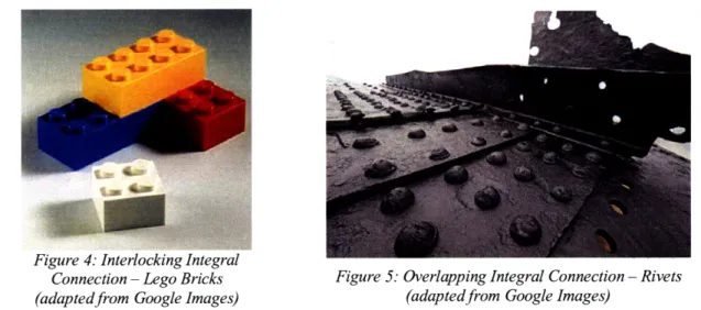
shear. (Durmisevic and Brouwer [2002a] 17) The geometry may be characterized as either an interlocking-type connection or an overlapping-type connection. An interlocking-type connection requires no accessory parts; the pieces themselves have male and female protuberances that combine to create a strong connection. The ease of assembly and disassembly without additional parts makes interlocking-type connections ideal for building toys; the best-known example is the Lego brick, shown in Figure 4. The interface between a nut and a bolt,
strictly speaking, is also an interlocking-type connection. Unfortunately, the tolerances required to fabricate interlocking elements and the dangers of local failure preclude the adoption of such connections on a structural scale. In an overlapping-type connection, each element laps onto the next, typically requiring an accessory part to complete the connection. Overlapping-type
Figure 4: Interlocking Integral
Connection- Lego Bricks Figure 5: Overlapping Integral Connection - Rivets (adaptedfrom Google Images) (adaptedfrom Google Images)
connections are best suited to plate-like elements to cover fagades and other surfaces. As a historical example of an overlapping-type connection, rivets were commonly used for fixing steel plates, as shown in Figure 5, before speed of assembly and safety concerns caused their obsolescence in favor of direct bolted connections. Wood clapboards and aluminum siding, fixed with nails and screws, demonstrate the diversity of such connections found on modern fagades. Deconstructability of an overlapping-type connection depends largely on the accessory part used for the connection and the damage it causes to the original pieces.
Accessory connections are interfaces in which the two elements are held together indirectly, using parts that resist forces primarily through bearing. (Durmisevic and Brouwer [2002] 17) They are characterized by their ease of assembly and disassembly. The subdivisions of accessory connections are internal-type connections
Figure 6: Internal-Type
Accessory Connection -Bolts and external-type connections. Internal-type connections
(adaptedfrom Google Images)
incorporate accessory parts inserted directly through the elements, requiring some damage to the pieces to create a bearing surface. Most bolted steel connections, like the one shown in Figure 6, are internal-type connections. These connections types are
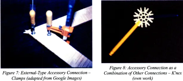
among the most common in steel design, and the only disadvantages are the precision and effort needed to create bolt holes and the resulting damage to the elements. External-type connections act without penetration, using other means to provide the necessary resistance. A clamp, creating bearing capacity by increasing the frictional force, as shown in Figure 7, is a good
Figure 8: Accessory Connection as a Figure 7: External-Type Accessory Connection - Combination of Other Connections - K'nex
Clamps (adaptedfrom Google Images) (own work)
example of an external-type connection. These connections are rarely used in construction because of their low capacities; their potential applications are discussed in Section 5.2.
Technically, an accessory connection may be thought of as a combination of integral connections, filled connections, or both, if the accessory piece is instead considered to be a third element. To use another building toy example, K'nex parts come in two main types: rods and connectors. Figure 8 shows a K'nex connector joining two K'nex rods. The assembly contains two interlocking-type integral connections; however, the assembly functions as a single external-type accessory connection, in which the rods are the primary elements and the connector is the accessory. Steel connections may be described in a similar way.
4. Optimal Connection Design Using Traditional Methods
4.1. Welds, Dowel Bolts, and High-Strength Friction Grip Bolts
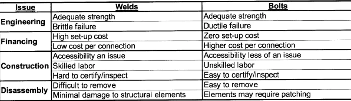
Among all possible steel connections, the most common in practice (and the least expensive, thanks to their familiarity among contractors) use plates and angles - accessory connections -attached to the main elements using either welds or bolts. In fact, the majority of common connection types use bolts and welds in conjunction. A central question for this thesis is whether bolts should be preferred over welds or vice versa, or if both are equally acceptable. The answer depends largely on the nature of the structure and the resources of the contractors. A summarized comparison between the two can be found in Table 1.
The AISC applies high resistance factors to connection design, such that all global failure modes of the system may be assumed to involve failure of members, not connections. (AISC 90) Both welds and bolts are subject to the stringent requirements of the AISC, and it may be said that
Table 1: Comparison of Welds and Bolts
Issue Welds Bolts
Adequate strength Adequate strength
Engineering Brittle failure Ductile failure
Financing High set-up cost Zero set-up cost
Low cost per connection Higher cost per connection
Accessibility an issue Accessibility less of an issue
Construction Skilled labor Unskilled labor
Hard to certify/inspect Easy to certify/inspect
Difficult to remove Easy to remove
Minimal damage to structural elements Elements may require patching
nominally all properly designed connections have the same strength. Welds may assume a variety of thicknesses and configurations, while bolt sizes and quantities may likewise be chosen to support the necessary load. Thus, from a purely structural perspective, there is a slight preference for bolts only because of their usual failure mode. Bolts have a tendency to exhibit plastic deformation prior to failure, as opposed to welds which may fail suddenly. This issue primarily presents itself during disassembly; when welds are being removed they can break without warning, a dangerous and undesirable possibility. Consequently, removing connections with critical welds requires the constant aid of a crane to ease the load on the connections, and
places weld removal on the critical path of disassembly sequencing, at great cost. Since bolt stability can be determined easily during disassembly, a crane is not needed until the moment a member is ready for removal. (Webster and Costello 5)
From a construction standpoint, it is preferable to make a decision for an entire structure as to whether bolts or welds will be used. Welding has a very high set-up cost, making it uneconomical for small buildings, but its lower cost-per-connection makes it preferable to bolting in larger projects. Owens and Cheal have estimated that the lower limit for a project to economically favor welds over bolts is 500-1000 tons. (Owens and Cheal 129) It is unreasonable to switch between welded connections and bolted connections in the same project, both because it makes the building more complex (inhibiting assembly and disassembly) and because there is necessarily a more economical solution by tending one way or the other. Practically, bolting requires less stringent accessibility requirements, less worker expertise, and less certification;
additionally, bolted connections are far easier to inspect. (Owens and Cheal 129)
Disassembly, not surprisingly, has nearly the same issues as assembly. As welded connections are easier to install in a building, requiring less working area and less structural support, so are
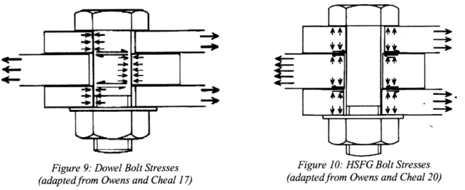
Figure 9: Dowel Bolt Stresses Figure 10: HSFG Bolt Stresses (adaptedfrom Owens and Cheal 17) (adaptedfrom Owens and Cheal 20)
welded connections easier to remove. On the other hand, a steel member with bolt holes may not be reusable unless the old holes are first patched. Thus, bolted steel is not strictly reused, but rather remanufactured, or restored to good-as-new condition, much like a disposable camera. The process of remanufacture still requires far less energy than straight recycling. (Durmisevic
and Brouwer [2002b] 6) In fact, in cases where the entire building is to be moved and reassembled, the bolt holes need not be filled. (Webster and Costello 8)
Where welds must be used, fillet welds are preferred to butt welds for a number of reasons. It has been noted that a single-pass fillet weld is considerably less expensive than a full-penetration butt weld for a given structural strength. (Owens and Cheal 129) Moreover, butt welds are very difficult to remove, and they require coping
of the elements they connect, compromising
186.3 kN the integrity of the pieces for reuse.
180-1589k
160-There exist two different types of bolts for
140 M24 8.8 bolt
140 t
two primary methods of carrying load.
Dowel bolts, shown in Figure 9, are by far '120
the most commonly used. They transfer 6t0o- M24 general
. grade HSFG
shear in bearing between the inside surfaces M go bolt
bo-of adjacent bolt holes, and are not designed
60-to sustain any force other than shear.
(Owens and Cheal 27) If friction between 4-elements is desired, then high-strength 20
-132.4kN friction grip (HSFG) bolts, which can carry
20 40 60 0 100 120 140 tension to create a clamping force, must be 40 0 o20 r )100 120 140
used, as shown in Figure 10. For a given Figure 11: Strength of Dowel Bolts and HSFG Bolts
grade, HSFG bolts tend to have a lower (adaptedfrom Owens and Cheal 130)
design strength than dowel bolts; a comparison is given in Figure 11. They are also more expensive to install, requiring powerful torquing equipment to tighten the nuts to the necessary tension. (Owens and Cheal 130) In standard bolted connections, HSFG bolts are only required if the small amount of slip necessary for a dowel bolt to enter bearing against the elements it connects cannot be accommodated in the structure. For this reason, they are rarely even considered in standard construction, though several recent innovations in connection design could make them more useful.
4.2. Shear Connections
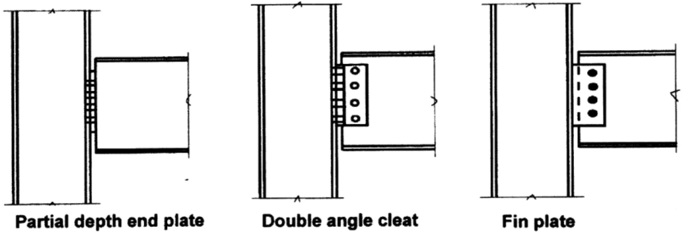
Shear connections, also known as simple connections, are beam supports designed to carry only shear, no moment. They are appropriate for most girders in a building, which are idealized whenever possible as simple spans with pin supports. True pins are generally not used because of the practical difficulties of creating such a connection. Instead, it is assumed that the web of a girder does not carry moment, while the flanges do. An axial stress distribution for a generic W-shape under uniform load demonstrates the validity of this assumption. That said, the end of a simply connected beam still rotates when the beam is loaded, causing the bottom flange to displace outward and the top flange to displace inward. As bearing between the bottom flange and the column is undesirable both for the integrity of the connection and the strength of the column, it is standard to extend shear connections at least 10mm (3/8") from the column. (Davison and Owens 728) Therefore, shear connections never specify a direct connection between beam and column, but instead use accessory connections with intermediate plates or angles.
Shear connections may frame into either a column flange or a column web; the difference in strength is negligible. Often it is the orientation of the column that determines the specific framing of the connection, since most columns support girders from two orthogonal directions, limiting choices. But given the option, it is preferable to frame a beam into a column flange.
I e
o
1
Partial depth end plate Double angle cleat Fin plate
Figure 12: Overview of Shear Connections (adaptedfrom Davison and Owens 722)
The flange connection offers better access for bolting or welding during both assembly and disassembly, saving time and money on-site. More importantly, to fit a girder into the space
between two flanges requires that the beam be lowered into place from the top of the column, which clearly requires more planning and an increased use of labor and equipment. Worst of all, the beam's flanges may require coping at the end to fit. Although the effect of coping on the beam's strength is well-documented and accounted for in design, the effect on the beam's salvage value is significant. One solution to avoid coping when a beam must frame into a column web is to use an extended fin plate connection, described below. Hollow structural steel
(HSS) columns avoid the issue by having no concavities,
but the hollow interior complicates the assembly by making fully bolted connections impossible.
The three main types of shear connections are shown in Figure 12: fin plates, flexible end plates, and double-angle cleats. All three are accessory connections, with
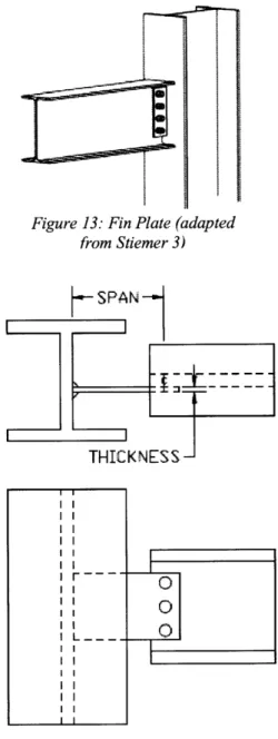
Figure 13: Fin Plate (adapted
the name of the connection describing the accessory from Stiemer 3) piece. Fin plates, also known as shear tabs, are oriented
parallel to the axis of the beam such that a face rests
K
1against the web of the beam and an edge rests against the
column. They can be used either singly or in pairs -depending on the required strength of the connection.
Dowel bolts connect the fin to the beam web, while a THICKNESS weld connects the fin to the column. (Davison and Owens
736) A construction advantage of fin plate connections is that the plates can be shop-welded to the columns, as
shown in Figure 13. This preparation makes the beams i
easy to attach on-site, and equally easy to detach during I L _ _ O disassembly.
An extended fin plate is a variation in which a beam to be Figure 14: Extended Fin Plate Design
shear-connected to the web of a column ends before (own work)
reaching the column flange, making coping unnecessary. To complete the connection, a plate projects from the column web to connect to the beam web, via bolts as usual, but with a longer
span than a typical shear tab. It is advantageous to avoid the many additional limit states that coping produces - lateral-torsional buckling (LTB), local buckling of the web, and beam block shear - and instead rely on an extended connection. (Rahman et al. 1) The downside is that the elongated fin may itself fail in LTB. As a rule, to avoid LTB, it is suggested to specify the thickness of the plate at a minimum of 15% of the distance from the column weld to the center-line of the bolt group, as shown in Figure 14. (Davison and Owens 737) Models and experiments performed by Rahman et al. have demonstrated that it is possible to design extended shear tabs that fail primarily by punching of the fin into the column web, the same failure mode as for regular fins and at a similar ultimate strength. (Rahman et al. 7)
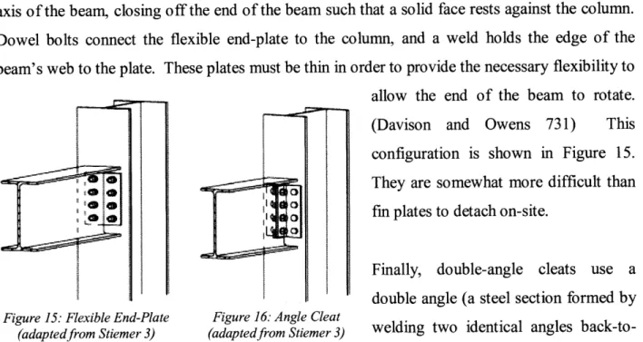
Flexible end-plates are, in a way, the opposite of fin plates: they are oriented perpendicular to the axis of the beam, closing off the end of the beam such that a solid face rests against the column. Dowel bolts connect the flexible end-plate to the column, and a weld holds the edge of the beam's web to the plate. These plates must be thin in order to provide the necessary flexibility to allow the end of the beam to rotate. (Davison and Owens 731) This configuration is shown in Figure 15.
0 They are somewhat more difficult than
,- fin plates to detach on-site.
Finally, double-angle cleats use a double angle (a steel section formed by
Figure 15: Flexible End-Plate Figure 16: Angle Cleat
(adaptedfrom Stiemer 3) (adaptedfrom Stiemer 3) welding two identical angles back-to-back) with the leg pointed toward the beam and the crossbar placed against the column. Web cleats are attached to both beam web and column using dowel bolts, which is more expensive but easier to accomplish on-site and more adaptable to small discrepancies in site conditions. (Davison and Owens 731) Also, of course, the use of only bolts makes the connection the easiest of the three to disassemble and the least damaging to both beam and column, though the bolt holes will require patching. Double-angle cleats are shown in Figure 16.
4.2.2. Moment Connections
Moment connections, also known as rigid or semi-rigid connections, resist bending as well as shear. This thesis focuses on moment connections in beam-to-column interfaces; moment connections may be found at other types of interfaces, but the principles are largely the same. From a perspective of static determinacy, it is usually preferable to avoid moment connections, but there are many structural configurations for which such connections cannot be avoided. Bending continuity is required anywhere that a beam cantilevers beyond a column to a free end; if the beam does not pass through or over the column, it must be given a moment connection and a back-span. All buildings require a lateral force-resisting system, and wherever diagonal braces or shear walls are architecturally undesirable a moment frame must be used, with many moment connections in a row, along several orthogonal column lines. Buildings in seismically active regions often take the moment frame a step further and specify the majority of connections in a
steel structure as moment connections for added stiffness. (Davison and Owens 755)
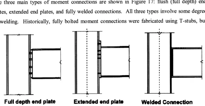
The three main types of moment connections are shown in Figure 17: flush (full depth) end plates, extended end plates, and fully welded connections. All three types involve some degree of welding. Historically, fully bolted moment connections were fabricated using T-stubs, but
Full depth end plate
Extended end plate
Welded Connection
Figure 17: Overview ofMoment Connections (adaptedfrom Davison and Owens 722)
these have lost popularity due to the need to incorporate HSFG bolts for the beam flange connections, as well as sheer number of bolts required. (Owens and Cheal 191) Among the three main types used today, the two end plate connection types limit the welding to the ends of the beams, while fully welded connections place a weld line on both beam and column. An end
plate effectively turns a moment into a couple, resisting a tension force on the top half of the plate and a compression force on the bottom half. While extended end plates require a longer weld, they also provide a longer lever arm for this couple. (Owens and Cheal 191) For the purpose of disassembly, the increased accessibility and the reduced shear stress placed on individual bolts make extended end plates preferable to flush end plates. Fully welded connections should be avoided at all costs. Even if a weld can be removed, the tendency for welds to exhibit brittle failure demands that a crane support the beam throughout weld removal, excising the connection of its load-bearing function. This inefficient use of a crane is sufficiently economically infeasible to preclude any disassembly effort involving fully welded connections.
Figure 18 shows some common methods of stiffening columns at moment connections, where the column web requires additional strength under concentrated tension, concentrated
Rb tension Full depth
sttrfener t temion s Tension stiffeners Compression stiffeners Fklnge backing plate Mornis
N ffener Stiffener K stiffener
Commonly used method of shear stiffening
Figure 18: Methods of Axial and Shear Stifening for Moment Connections (adaptedfrom Davison and Owens 766)
compression, or shear. (Davison and Owens 766) With the exception of the bolted "flange backing plate" for a top flange in high tension, all common stiffeners are welded to the column.
Nevertheless, stiffener welds are not as serious a deterrent to disassembly as welds directly related to connections. A column may be removed from a building assembly with stiffeners intact; the stiffeners may be taken out later, off the critical path of construction scheduling, or left in where they certainly do not adversely affect the column's strength when reused. Moment connections should frame into column flanges wherever possible; a moment connection that frames into a column web virtually guarantees that the web will require heavy stiffening. A correctly designed moment connection, with an appropriately sized beam framing into the flange of a sufficiently heavy column, requires no stiffeners at all. (Davison and Owens 765) In addition to making assembly and disassembly simpler, designing moment connections to minimize the stiffening needed avoids many unnecessary welds, tremendously improving
5.
Innovations in Connection Design
5.1. Standardized Systems
Successful building toys can offer surprising insights into the structural systems of real-life construction. The Erector set was wildly popular among engineers-to-be for most of the 2 0th
century, fading only in the past 30 years as plastic toys outpaced their metal predecessors. From a limited array of pre-holed members, pre-holed plates, nuts, and bolts, Erector users could build a vast array of model structures with ease - and, just as quickly, take apart the pieces to build something new. Every piece in the set could be reused indefinitely, the ultimate in sustainable construction.
There is no compelling reason why the principles of an Erector set cannot be applied to actual steel structures. If steel members and connections were chosen not from the vast offerings of fabricators but from a minimal kit of parts, the result would be increased ease of assembly and disassembly, and unparalleled potential for reuse. Webster and Costello give some idea of how such a system could operate. Bolt holes could be pre-drilled at the ends of beams and at regular intervals along columns. Connection angles and plates could be designed to fit the available members, and a limited number of bolt gauges could ensure compatibility throughout the system. (Webster and Costello 8) Buildings with routine
geometry could be assembled and disassembled far faster than any conventional structural system would allow.
An existing example of such a system is Quicon, developed in the early 2000s by the Steel Construction Institute (SCI), a consultant based in
the United Kingdom. (Steel Construction Figure 19: Quicon Schematic (adaptedfrom Aveni 1)
Institute) Quicon provides brackets and shoulder bolts for steel beam connections; the T-brackets include a series of keyhole-shaped notches that the shoulder bolts securely slide into on-site. To further speed assembly, both the T-brackets and the shoulder bolts can be attached to
members off-site. Figure 19 gives a schematic of how the system works. While Quicon has not received widespread market attention, its advantages over traditional steel construction are numerous. It can be built in roughly half the time needed to build a similar frame with normal, welded connections. It improves construction safety and quality, since bolts are pre-installed and the only work done on-site is fitting the bolts into the connection holes. It can alleviate the need for an inspector to check
Figure 20: Application of Quicon (adaptedfrom Crates 1) every last connection once the frame is
complete. And, because no welds are required, it can easily be taken apart and reused elsewhere. An application of Quicon is shown in Figure 20.
The applications of Quicon are probably limited to simple geometries like warehouses and parking garages, which may explain why it has not been widely used in the eight years since the SCI first released the system.
Nevertheless, the system sets a superb example for future disassembly-enabling systems.
5.2. Clamped Friction Connections
In Figure 21, a wood block sits on a table. To slide the wood block
across the table, it is necessary to Figure 21: Wood Block, No Clamp Figure 22: Wood Block, Clamped
apply a horizontal force equal to (own work) (own work)
the frictional force between the materials, which in turn is a function of the normal (vertical) force between the materials and the coefficient of friction. If one wishes to make it more difficult to slide the block off, one may increase the frictional coefficient by roughening the wood and table surfaces; this tactic, however, is limited by the amount of damage one is willing to inflict on the materials. A far more effective tactic is to increase the normal force, which is
done easily with the addition of a C-clamp and does not damage the materials as long as they do not fail in bearing.
Essentially, a C-clamp works by putting a length of steel (the C) in tension, and balancing the tension with an equal compressive force applied to the objects inside the clamp, as shown in Figure 22. Bolted friction connections in construction are modeled after this simple mechanical process. Standard dowel bolts, however, are designed to resist only shear, not to take tension. As discussed in Section 3.1, nuts are typically specified to "snug" tightness, an imprecise measure indicating the bolt should stay in place but not be under axial stress. Friction connections require HSFG bolts, which are designed specifically to act in tension in order to apply a compressive force to the elements in between. The advantage of friction connections over standard bolted connections is that the HSFG bolts need not penetrate these elements - they can be external-type connections rather than internal-type connections.
One friction connection system currently on the market is Lindapter. A schematic of a Lindapter girder clamp, shown in Figure 23, gives a good idea of what is to be gained by using a friction connection. One bolt is applied at each of the four corners between two orthogonal girders, with specially shaped clamp components including a toe to transfer the axial force of the bolt into normal force between the girders. A plate is specified in between the girders to ensure a proper location for the four C' bolts. The connection is no more difficult to design, install, and disassemble than a traditional bolted connection, and since it does not penetrate either girder it does not diminish their salvage value whatsoever, with the caveat that bearing is not exceeded. Lindapter also provides connections for higher-friction applications such as beam-to-column shear connections, as shown in Figure 24, but the strength is sufficiently low that only secondary steelwork could warrant such a connection. Also, Lindapter beam-to-column systems
Figure 23: Lindapter Connection
flexible end plate shear connection, so it is only the column that receives the undisturbed advantage in deconstruction.
Still in the testing stage is a friction connection that resists beam-to-column moment connections. The scheme, known as a "post-tensioned moment connection", was developed at Lehigh University in the late 1990s. (Ricles et al. [2006] 1) As the name implies, the connection develops its moment capacity through post-tensioned high-strength strands that run parallel to the beams and tie off at exterior columns. Figure 25 shows how these post-tensioned strands serve the same function as the HSFG bolts used
Figure 24: Lindapterfor Beam-Column
Application (adaptedfrom Lindapter) above, putting the beam into compression and thereby
compressing the beam flanges against the column flanges. (Ricles et al. [2000] 182) Seat angles and top angles resist shear, completing the connection. A report on early tests done on this system touts the many potential benefits of what has been dubbed the "Lehigh Scheme": no welding is necessary; the strength of the connection approximates that of a standard, fully
PT SStrands Shim Plate Post-Tensioned trands S---7=, niReinforcing Anchors Plate Angle
Figure 25: Post-Tensioned Moment Connections (adaptedfrom Ricles et al. [2000], 182)
welded moment connection; the post-tensioned connection dissipates the energy of an earthquake through plastic deformation while keeping beams and columns elastic; and the angles are easy to replace following deformation. (Ricles et al. [2000] 181) In short, the scheme is adaptable through its seismic performance, deconstructable thanks to the lack of welds, and reusable because the external-type friction connection, unlike a standard moment connection,
does little to damage the members. __
Contractors and structural engineers should embrace the capacities of standardized systems like Quicon and clamped friction connections like Lindapter where such applications are fit, and they should encourage the marketing of as-yet-unused innovations like post-tensioned moment connections. The value of these systems to DfD demands further exploration.
6. Conclusion
The principles of DfD suggest many strategies for enabling the disassembly of a building at its end of life through decisions made in the design phase. While some such strategies are unlikely to be adopted in the near future, connection design for maximum deconstructability can be accomplished largely through methods already familiar to contractors and structural engineers. Bolts should be preferred over welds wherever possible: although both demand some remanufacturing of materials to prepare them for reuse, bolts are far easier to disassemble. In shear beam-to-column connections, angle cleats provide fully bolted interfaces. If the number of bolts required is prohibitive, extended fin plates should be considered where a regular fin plate or a flexible end-plate would require coping of the beam. In moment beam-to-column connections, the use of welding is usually unavoidable, but proper member specification and column orientation can minimize the requirements for stiffeners. Where they are relevant, certain innovations in connection design, such as standardized systems of components and clamped friction connections, can prevent the need for any remanufacturing at all and thereby make disassembly even more successful. As an overriding principle, the best connection design strategies preserve the independence of the members, enhancing both deconstructability and reusability.
It is hoped that this thesis will be recognized by professional builders and will help to reform building design and construction, with the goal of reducing the industry's vast energy requirements through the simple principle of reuse.
Works Cited
American Institute of Steel Construction, Inc. (AISC). Specification for Structural Steel Buildings. American Institute of Steel Construction, Inc., 2005.
Aveni, Madonna. "Steel Connector Could Reduce Assembly Time." Civil Engineering, October 2001.
Catalli, Vince and Williams, Maia. "Designing for Disassembly." Canadian Architect, January 2001.
Crates, Emma. "A Steel Slot System that Speeds Up Connection." Construction News, March 2002.
Davison, Buick and Owens, Graham W. Steel Designers' Manual, 6th Ed. Oxford, UK: Steel
Construction Institute/Blackwell Publishing, 2003.
Durmisevic, Elma and Brouwer, Jan [2002a]. "Design Aspects of Decomposable Building Structures." Proceedings of the Deconstruction and Materials Reuse Conference, Karlsruhe, Germany, 2002.
Durmisevic, Elma and Brouwer, Jan [2002b]. "Dynamic versus Static Building Structures."
Proceedings of the International Postgraduate Research Conference in the Built and Human Environment, Salford, UK, 2002.
Durmisevic, Elma and Noort, Nico. "Re-use Potential of Steel in Building Construction."
Proceedings of the CIB TG 39 - Design for Deconstruction and Material Reuse Conference,
Delft, Netherlands, 2003.
Google Images. http://images.google.com.
Lindapter. "Steelwork Fixings." http://www.lindapter.com/PDFs/SteelworkSection.pdf, accessed 6 April 2009.
Morgan, Chris and Stevenson, Fionn. "Design for Deconstruction." SEDA Design Guides for
Scotland, n.1, 2005. http://www.seda2.org/dfd/dfd.pdf, accessed 14 May 2009.
Owens, Graham W. and Cheal, Brian D. Structural Steelwork Connections. London, UK: Butterworth & Co. (Publishers) Ltd, 1989.
Rahman, Adeeb; Mahamid, Mustafa; Ghorbaanpoor, Al; and Amro, Akef. "Failure Modes of Extended Shear Tab Steel Connections." Proceedings of the ASCE Engineering Mechanics
Ricles, J.M., Sause, R., and Garlock, M. [2000]. "Post-Tensioned Moment Connections for Seismic Resistant Steel Frames." Proceedings of the AISC International Workshop on
Connections in Steel Structures, Roanoke, USA, 2000.
Ricles, J.M., Sause, R., Wolksi, M., Seo, C-Y., and Iyama, J. [2006]. "Post-Tensioned Moment Connections with a Bottom Flange Friction Device for Seismic Resistant Self-Centering Steel MRFs." Proceedings of the International Conference of Earthquake Engineering, Taipei, Taiwan, 2006.
Sarja, Asko. Integrated Life Cycle Design of Structures. London, UK: Spon Press, 2002. Sassi, Paola [2002]. "Study of Current Building Methods that Enable the Dismantling of Building Structures and their Classifications According to their Ability to be Reused, Recycled or Downcycled." Proceedings of the World Sustainable Building Conference, Oslo, Norway, 2002.
Sassi, Paola [2008]. "Defining Closed-Loop Material Cycle Construction." Building Research
& Information, v.36, n.5, September 2008.
Steel Recycling Institute. http://www.recycle-steel.org. Accessed 2 March 2009.
Steimer, S.F. "Bolted Beam-Column Connections (Design and Cost Estimation)." November 2007. http://www.sigi.ca/engineering/documents/bolted_beam_column_connections.pdf, accessed 13 May 2009.
Webster, Mark D. "Structural Design for Adaptability and Deconstruction: A Strategy for Closing the Materials Loop and Increasing Building Value." Proceedings of the 2007 ASCE
Structures Conference, Long Beach, USA, 2007.
Webster, Mark D. and Costello, Daniel T. "Designing Structural Systems for Deconstruction: How to Extend a New Building's Useful Life and Prevent it from Going to Waste When the End Finally Comes." Proceedings of the 2005 Greenbuild Conference, Atlanta, USA, November 2005.
![Figure 2: Connection Schematics (adaptedfrom Durmisevic and Brouwer [2002a] 17)](https://thumb-eu.123doks.com/thumbv2/123doknet/14056888.460830/11.918.105.796.247.359/figure-connection-schematics-adaptedfrom-durmisevic-brouwer-a.webp)