Publisher’s version / Version de l'éditeur:
Vous avez des questions? Nous pouvons vous aider. Pour communiquer directement avec un auteur, consultez la première page de la revue dans laquelle son article a été publié afin de trouver ses coordonnées. Si vous n’arrivez pas à les repérer, communiquez avec nous à PublicationsArchive-ArchivesPublications@nrc-cnrc.gc.ca.
Questions? Contact the NRC Publications Archive team at
PublicationsArchive-ArchivesPublications@nrc-cnrc.gc.ca. If you wish to email the authors directly, please see the first page of the publication for their contact information.
https://publications-cnrc.canada.ca/fra/droits
L’accès à ce site Web et l’utilisation de son contenu sont assujettis aux conditions présentées dans le site LISEZ CES CONDITIONS ATTENTIVEMENT AVANT D’UTILISER CE SITE WEB.
GeoEdmonton '08: 61st Canadian Geotechnical Conference [Proceedings], pp.
1-8, 2008-09-21
READ THESE TERMS AND CONDITIONS CAREFULLY BEFORE USING THIS WEBSITE.
https://nrc-publications.canada.ca/eng/copyright
NRC Publications Archive Record / Notice des Archives des publications du CNRC :
https://nrc-publications.canada.ca/eng/view/object/?id=5046598e-6cae-4213-84ae-f065e12c793a
https://publications-cnrc.canada.ca/fra/voir/objet/?id=5046598e-6cae-4213-84ae-f065e12c793a
NRC Publications Archive
Archives des publications du CNRC
This publication could be one of several versions: author’s original, accepted manuscript or the publisher’s version. / La version de cette publication peut être l’une des suivantes : la version prépublication de l’auteur, la version acceptée du manuscrit ou la version de l’éditeur.
Access and use of this website and the material on it are subject to the Terms and Conditions set forth at
Instrumentation for field monitoring in expansive soils
Hu, Y.; Azam, S.
http://irc.nrc-cnrc.gc.ca
I nst rum e nt a t ion for fie ld m onit oring in ex pa nsive soils
N R C C - 5 0 8 1 3
H u , Y . ; A z a m , S .
S e p t e m b e r 2 0 0 8
A version of this document is published in / Une version de ce document se trouve dans:
GeoEdmonton '08 - 61st Canadian Geotechnical Conference, Edmonton, AB.
September 21-24, 2008, pp. 1-8
The material in this document is covered by the provisions of the Copyright Act, by Canadian laws, policies, regulations and international agreements. Such provisions serve to identify the information source and, in specific instances, to prohibit reproduction of materials without written permission. For more information visit http://laws.justice.gc.ca/en/showtdm/cs/C-42
Les renseignements dans ce document sont protégés par la Loi sur le droit d'auteur, par les lois, les politiques et les règlements du Canada et des accords internationaux. Ces dispositions permettent d'identifier la source de l'information et, dans certains cas, d'interdire la copie de documents sans permission écrite. Pour obtenir de plus amples renseignements : http://lois.justice.gc.ca/fr/showtdm/cs/C-42
Instrumentation for field monitoring in expansive
soils
Yafei Hu
National Research Council Centre for Sustainable Infrastructure Research
, Regina,
SK, Canada
Shahid Azam
Environmental Systems Engineering, University of Regina, Regina, SK, Canada
ABSTRACT
Expansive soils are subject to large volume changes in arid and semi-arid regions due to seasonal climatic variations. Alternate swelling and shrinkage of the soils results in distress and even failure of lightweight infrastructure. To ensure the durability of infrastructure built on expansive soils, it is essential to understand the in situ changes in soil conditions over time. This paper presents an instrumentation protocol for the field monitoring of expansive soils and discusses various types of sensors for capturing soil movement, water content, soil pressure, and temperature. It provides recommendations for selecting and installing appropriate sensors in expansive soils.
RÉSUMÉ
Les sols expansibles subissent des changements de larges volumes dus aux variations climatiques saisonnières. Les gonflements et de rétrécissements alternatifs sèment la détresse et même l’échec dans les systèmes d'infrastructure civile. Pour assurer l'utilisation non interrompue d'une facilité, il est essentiel de comprendre les changements in situ des conditions de sol avec le temps. Cet article développe un protocole d'instrumentation pour la surveillance de champ des sols expansibles. De divers types de sondes (pour le mouvement de serrage de sol, la teneur en eau, et la température), de leurs procédures d'installation, et d'interprétation de données dans les sols argileux sont discutés. Des recommandations sont données pour choisir et installer les sondes appropriées dans les sols expansibles.
1 INTRODUCTION
Expansive soils are commonly found in the arid and semi-arid regions of the globe and are known to exhibit large volume changes due to water content changes. Alternate swelling and shrinkage due to seasonal variations in precipitation and evaporation can cause severe distress and even failure of lightweight structures constructed on or buried in such soils, thereby compromising their service life. To ensure the uninterrupted use of infrastructure, it is essential to understand the in situ changes in relevant soil conditions over time.
Over the years, instruments have been developed for the field monitoring of soil displacement, water content, soil pressure, and soil temperature and have been used in a variety of applications. Some of the instruments can be readily employed for monitoring in situ conditions in expansive soils, whereas others need to be modified prior to their application or installed in a special fashion. Custom-made instruments are also available for special applications and for capturing specific characteristics of soils.
The objective of this paper is to present an instrumentation protocol for the field monitoring of expansive soils. Based on reported case studies, this paper describes the use of various types of sensors and procedures for their installation in clayey soils. Recommendations are given for: (i) the selection of appropriate sensors for monitoring soil conditions (soil displacement, water content, soil pressure, and temperature); and (ii) guidelines for installing the selected devices in expansive soils, while minimizing soil disturbance.
2 SOIL CHARACTERISTICS THAT AFFECT
MEASURING ACCURACY
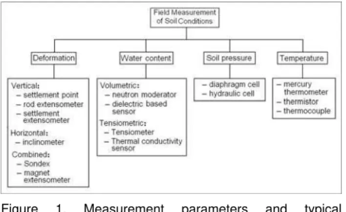
The field monitoring of soil movement, water content, soil pressure, and temperature in expansive soils must consider the unique characteristics of this type of soil. The selection of appropriate monitoring devices and installation techniques should be carefully designed to ensure successful functioning and generation of meaningful data. Figure 1 shows the parameters that can be monitored and the typical instruments used to understand expansive soil behaviour. This section presents the characteristics of expansive soils and their effect on instrumentat selection.
First, expansive soils show periodic swelling/ shrinkage due to seasonal climatic changes. Such cyclic volume changes result in a network of cracks in the soil. If sensors are installed in the cracks, air gaps can introduce systematic measuring errors (Bridge et al., 1996). Cracks can also affect the positioning of some types of sensors and can result in faulty data generation. Large cracks, which may exist particularly near the ground surface, can significantly affect readings when they occur between instrument sensor rods. If the sensors are inserted in the soil blocks between cracks, readings may not be representative of the actual bulk soil conditions. Periodic volume changes in expansive soils can also result in shifting sensor positions and possible damage to the instruments.
Second, soil suction is one of the stress state variables controlling the behaviour of expansive soils (Fredlund and Rajardjo, 1993) and special instruments are required to monitor it.
Figure 1. Measurement parameters and typical instruments for expansive soils
Third, in contrast to the typical three-phase (solid particle, water and air) structure of soils, expansive soils have thin layers of water bonded to the negatively charged clay mineral surfaces. This adsorbed water is not free to move the way liquid water can. The dielectric constant for the bound water is closer to that of ice and much lower than that of liquid water (Dirksen and Dasberg, 1993). This means special calibrations are needed to measure water content in expansive soils as described later.
Fourth, expansive clays are typically characterized by a high electrical conductivity (EC) resulting from the colloid surface and the electrolytes in the soil solution. This also affects the accuracy of moisture content measurement. The effect of soil EC on water content measurement has been discussed by Topp et al. (1980), Topp et al. (2000), Malicki et al. (1994), and White et al. (1994).
Soil temperature is monitored to understand the effects of seasonal changes. Some soil properties may change with temperature because it affects some other characteristics. For example, bound water may become free water as soil temperature increases, affecting the accuracy of water content measurements. In addition, some sensors may not work below 0 oC.
3 INSTRUMENTATION FOR EXPANSIVE SOILS
3.1 Soil Displacement
Instruments for monitoring of soil displacement include those for measuring vertical displacement (heave and settlement) and those for recording horizontal movement (lateral displacement). A detailed description of such devices can be found in Dunnicliff (1993). To monitor the magnitude and rate of vertical and horizontal displacement on the ground surface, surveying methods are widely used. Geotechnical instruments are required for greater accuracy and/or when measuring points are inaccessible. For subsurface monitoring, both methods may be used in conjunction: geotechnical instruments measure soil displacements, while surveying is used to relate measurements to a set of reference points.
3.1.1 Vertical Displacement
Figure 2 shows instruments used for measuring vertical soil displacement. Subsurface settlement points (Figure
2a) are used for measuring settlements or heave in embankment and foundation soils. The device consists of a riser pipe anchored at the bottom of a vertical borehole and an outer casing to isolate the riser pipe from the effects of movement of soil above the anchor. Settlement or heave of the anchor is determined by measuring the elevation at the top of the riser pipe using surveying methods. The top of the outer pipe should also be surveyed in the event that it moves.
Many types of rod extensometers are available and vary, depending on anchor type (groutable, hydraulic, and packer), extensometer head (mechanical reference head, electric reference head), transducer type (fiberglass, stainless steel), and number of measurement points (single point borehole extensometer (SPBX), and multiple point borehole extensometer (MPBX)). Figure 2b shows an MPBX with several downhole anchors located in a single borehole. Each extensometer is attached to a rod from the downhole anchor to the reference head at the surface. MPBXs are used to monitor the displacement pattern along the axis of an appropriately oriented borehole. The distance from the face of the reference head to the end of the rod (downhole anchor) is measured using either a mechanical or an electrical transducer. This device has high precision but a narrow range (typically 50 to 100 mm).
There is settlement extensometer that can be used to monitor surface settlement or heave (up to 600 mm). It consists of an anchor, a stainless steel rod inside protective pipe, and a potentiometer inside a waterproof head (Figure 2c). The head is attached to the rod, tested, and covered with hand-compacted sand. A signal cable from the extensometer is connected to a data logger for remote readings. As the ground settles due to drying of expansive soils, the head moves downward. The potentiometer inside the head measures take-up of a tensioned wire.
The soil stratigraphy determines the anchor depth in a borehole. To seal the borehole and prevent water migration, hydraulic anchors (activated by a hand-operated pump) or packer anchors (activated by a high-pressure pump) can be used. All boreholes must be grouted unless the geology dictates otherwise. A weak and deformable (soft) grout is selected to couple the anchor with the surrounding soil. Care should be exercised while grouting to ensure conformance between the anchor and the surrounding soil. A single grout tube is adequate for both vertical and inclined holes. The tube end is taped to the protective pipe near the bottom anchor and the tubing drawn into the borehole as the extensometer is installed. A second shorter grout tube can be taped to a pipe about halfway down the extensometer length for backup. The tube is withdrawn from the
rotective pipe as the grout level rises in the borehole. p
(a). Subsurface settlement (b). Multiple-point rod point extensometer
(c). Settlement extensometer
Figure 2. Instruments for measuring vertical displacement 3.1.2 Lateral Displacement
Inclinometers can detect lateral movement and the direction of movement. Figure 3 shows the schematics for two main types of inclinometers. Probe inclinometers require manual operation, while in-place inclinometers digitally record displacements automatically. Both types contain servo-accelerometers that can be used to detect lateral movements of a casing. Since the voltage output is proportional to the sine of the sensor inclination angle from the vertical, the sensors measure deviations from the vertical. As shown in Figure 3a, the probe inclinometer is moved through a grooved casing installed in a borehole and extended to a depth below the expected movement zone (Dunnicliff, 1993). The casing bottom is grouted to ensure firmness.
(a). Probe inclinometer
(b). In-place inclinometer
Figure 3. Instruments for measuring lateral displacement Figure 3b shows one part of an in-place inclinometer consisting of a string of inclinometer sensors permanently deployed in a casing. The sensors are set to cover the desired zone of measurement and are connected to an automated data acquisition system that continuously monitors movements and can trigger an alarm if it detects a rate of change in deflection that exceeds a preset value.
If the inclinometer casing is installed along with Sondex pipe with a sensing ring or with a magnet extensometer, the system can measure settlement/heave as well (Slope Indicator, 2004). For a Sondex extensometer, a soft grout backfill couples the Sondex pipe to the surrounding ground, such that the pipe and rings move with settlement and heave. For a magnet extensometer, a spider magnet is grouted into the
borehole and the magnet moves with the settlement and heave of the surrounding ground.
3.2 Water content
Field water content measurement is important for understanding the behaviour of an expansive soil during wet-dry cycles and for verifying soil mechanics models (Fredlund, 2006). There are several methods for measuring soil-water content. Water content can be measured directly by the: (i) gravimetric method that measures the difference in weight before and after drying a soil sample; and (ii) volumetric method that calculates the water content based on the volume of water in a volume of undisturbed soil. This is useful in determining the degree of saturation of the soil. When expressed in terms of depth (volume of water in soil down to a given depth over a unit surface area), it can be compared with other hydrological variables like precipitation, evaporation, transpiration, and drainage. Despite being accurate and inexpensive, these direct methods are destructive, time-consuming, and do not allow for making repetitious measurements at the same location.
Several indirect methods are available for monitoring soil water content. In general, these methods have quick response time, do not require maintenance, and can provide continuous readings through automation (Munoz-Carpena, 2004).
Based on the measured output, indirect techniques are classified into volumetric and tensiometric methods. While the former gives volumetric soil water content, the latter yields soil suction or water potential (tension exerted by capillarity). These two quantities are related through the soil water characteristic curve for a given soil. The selection of suitable devices should consider the properties of expansive soils (texture and swelling and shrinkage characteristics) because measurement requires good soil-instrument contact.
3.2.1 Volumetric Methods
Volumetric methods estimate the volume of water in a sample volume of undisturbed soil. The methods can be grouped into neutron moderators and dielectric instruments (Figure 4).
A neutron probe based on neutron moderation is comprised of a long and narrow cylinder containing a decaying radioactive source (241Am/9Be) and a neutron detector (Figure 4a). The source gives off fast neutrons that collide with hydrogen atoms in the soil water, thereby slowing down rapidly. The detector captures neutrons and the water content of the soil with the sphere of influence can be calculated based on the number of slow neutrons detected.
Water content is measured by lowering the neutron probe into an access tube that, in turn, is directly installed in the soil for measurements near ground surface or in a borehole. Air gaps and soil disturbance that occur during access tube installation have minimal effect on the measurement results because the measurement is averaged after the volume within the sphere of influence of the probe. Still, care is warranted during installation of the access tube to prevent water flow along the tube and saturating the soil in the vicinity of the tube. The access
tube material should be chosen to achieve the desired results at a reasonable cost, since some materials may interfere with the results.
(a). Neutron moderation based probe
(b). Dielectric based instruments Figure 4. Volumetric water content measurement Neutron probes are not affected by salinity and can measure large water volume with high accuracy, thereby making it an ideal probe for use in unsaturated clays. However, the relationship between neutron count rate and water content is not unique. Variations can occur due to changes in organic matter, bulk density, the presence of neutron absorbents (boron, cadmium and chlorine in soils), and bound water in expansive soils. Therefore, site-specific calibrations are required to accurately calculate water content.
The dielectric method estimates soil water content by measuring the soil bulk dielectric constant (or permittivity) that determines the velocity of an electromagnetic wave through the soil. In a composite material like soil (made up of soil particles, water, and air), the bulk dielectric constant corresponds to the relative contribution of each of the components. Since the dielectric constant of liquid water (Klw = 79-82) is much larger than that of other soil
constituents (Ks = 2-5 for soil and Kair = 1 for air), the total
bulk dielectric constant is governed by the presence of liquid water (Look and Reeves, 1992).
Various dielectric methods have been developed to measure volumetric water content (Figure 4b). These include time domain reflectometry (TDR), water content reflectometry (WCR), amplitude domain reflectometry (ADR), and frequency domain reflectometry (FDR). Each method measures a different electromagnetic wave signal, but all use a probe embedded in the soil and an electromagnetic wave sent through it along the probe. The wave is reflected back and is captured by an oscillating electric circuit. During this process, signal properties are influenced by a bulk dielectric constant, thereby empirically correlating the probe output with soil properties.
The dielectric probe consists of 2 to 4 parallel metal rods inserted into the soil. For near ground surface measurement, direct insertion in the site or base of an excavation is recommended, whereas installation methods similar to those by Zhan et al. (2006) can be employed for deep subsurface applications. In the latter case, an access hole is drilled to a prescribed depth using an auger with a diameter larger than the head of the sensor. Next, special tools are used to slightly tamp the bottom of the hole while ensuring a level sensor head for good contact. Finally, the sensor is inserted in the hole and the space above the hole is backfilled using excavated soil. The backfill is tamped to a density similar to that of the surrounding soils to obtain a good seal. Care should be taken to avoid rod bending and breakage during insertion and tamping. If the probe needs to be retrieved later, the procedure can be modified by placing a tube centrally in the hole before sensor installation. The annular gap between the pipe and the wall of the hole is backfilled with a soil-cement mixture or a moist soil. In this case, the backfill materials are tamped to a relatively higher density to obtain a good seal.
Dielectric techniques are being widely adopted due to their instantaneous response, negligible maintenance, and real-time monitoring capabilities. The following factors should be considered when selecting dielectric sensors:
(i) calibration: The common approach to establish a relationship between the soil dielectric constant and volumetric water content is to use the empirical equation given by Topp et al. (1980). However, this equation is not valid for expansive soils and soil-specific calibration is required (Hu et al., 2006);
(ii) probe length: probes greater than 100 mm in length are recommended as shorter lengths may introduce substantial error in water content determination (Noborio, 2001). However, increased probe lengths lead to high conductive and polarization losses and result in an inverse relationship between probe length and measurement error (Ferré and Topp, 1999). A balance between measurement error and signal loss should be considered;
(iii) probe configuration: Three rod probes give better signal definition and are preferred for expansive soils with high salinity or several layers of high water content variation. However, the reflections from the beginning of the probe in dry and wet soils are very different and make
automated waveform interpretation difficult (Noborio, 2001);
(iv) spacing and diameter: The spacing and diameter of the probe rods significantly affect the probe impedance. Noborio (2001) reported that an increased wire spacing increased attenuation of the high-frequency content of the reflected signal. The ratio of rod diameter, d, to rod spacing, s, in two- and three-rod probes can be correlated to the concentration of energy surrounding the probe rod. As the probe diameter/spacing ratio increases, the concentration of energy immediately surrounding the rod increases and augments the sensitivity to local non-uniformities and air gaps. It is suggested that the probes with d/s > 0.1 should be used to reduce errors in water content determination;
(v) air gaps: Air gaps between the rods and soil significantly affect water content determination (Annan, 1997) and care is required during probe insertion to minimize the introduction of air gaps. Pilot holes are often used to aid probe insertion in stiff soils;
(vi) soil salinity: Soil salinity and highly conductive mineral clay contents affect dielectric-based probes. In soils with highly saline conditions, this effect can be minimized by using epoxy-coated probe rods. However, this results in loss of sensitivity and changes in calibration. The high mineral content in expansive soils tends to decrease the bulk dielectric constant as bound water has a lower dielectric constant than free water.
Finally, a model with empirical fitting parameters is needed to fit soils of varying texture because a single model may not be adequate for soils with different textures (Ponizovsky et al. 1999).
3.2 Te.2 nsiometric Methods
Tensiometric methods (Figure 5) estimate the soil water matric potential including both the adsorption properties and capillarity of soils. The matric potential is one of the components of the total soil water potential that also includes gravitational (position with respect to a reference elevation), osmotic (salts in soil solution), gas pressure or pneumatic (from entrapped air), and overburden components. The sum of matric and gravitational potentials is the main driving force for water movement in porous media such as soils.
All tensiometric instruments have a porous material in contact with the soil through which water can move. A tensiometer consists of a glass or plastic tube with a porous ceramic tip (Figure 5a). Water is drawn out of the porous tip in a dry soil and from the soil into the tip in a wet soil. Generally, the tensiometer does not need a soil specific calibration. In most cases, these devices have to be permanently installed in the field or a sufficiently long time must be allowed for equilibration between the device and the soil to occur before making a reading.
The top of the tensiometer tube has either a built-in vacuum gauge or a rubber cap used with a portable puncture tensiometer that uses a hypodermic needle to measure the pressure inside. When filled with water and inserted in soil, water can move through the tensiometer. As the soil dries and water moves out of the tensiometer, it creates a vacuum inside the tensiometer that is indicated on the gauge. When the vacuum created just
equals the “soil suction”, water stops flowing out of the tensiometer. The dial gauge reading is then a direct measure of the force required to remove water from the soil. If the soil dries further, additional water moves out until a higher vacuum level is reached. The reverse process takes place when water is added to the soil. Water from the soil moves back into the tensiometer through the porous tip until the vacuum level is reduced to equal the lower soil suction, then water movement stops. If water added to the soil is enough to achieve saturation, the gauge reading on the tensiometer drops to zero. Since water can move back and forth through the porous ceramic tip, the gauge reading is always in “balance” with soil suction.
Tensiometers give direct measurements, are suitable for automation and high frequency sampling, and are unaffected by soil salinity. However, they can only measure soil suction less than 100 kPa and require an intimate contact between soil and the ceramic tip for consistent readings. Due to swelling/shrinkage in expansive soils, the ceramic tip can lose contact with soil, thereby requiring reinstallation, and frequent maintenance in hot dry weather to refill the tube with water.
A thermal conductivity sensor consists of a heating element and a thermocouple embedded in a porous ceramic block (Figure 5b). Water from the surrounding soil can enter the block and equilibrate with the soil. A heat pulse is applied to the block using the small heating element and the temperature rise within the ceramic block is measured using a digital temperature sensor. The thermal conductivity of a porous media increases with increasing water content; more heat is dissipated when the heat pulse is applied if the block has a higher water content. Therefore, the measurements of temperature rise in the porous block (that has come to water potential equilibrium with the soil) can be used to measure the water content of the ceramic block.
The water content of the ceramic block depends on the matric suction of the soil surrounding the ceramic block. Hence, a measurement of the temperature rise in the porous block can be used to indicate the matric suction value in the soil. Such sensors can produce a reasonably reliable measurement of soil suction over a relatively wide range (5 to 1500 kPa) and over a long period of time without serving. However, the sensors need a sophisticated data acquisition systems to control heating and measurement operations and have slow reaction time in expansive soils (with low hydraulic conductivity) as the sensors need time to equilibrate with surrounding soils.
The general installation procedure consists of coring a proper diameter hole and inserting the sensor into the hole (Soilmoisture, 2005; GCTS, 2005). This procedure is not suitable for fissured expansive soils because cracks near the ground surface can lead to bypass water leakage into the installation hole, resulting in erroneous readings (Zhan et al., 2006). To prevent rainwater from leaking into the installation hole through the shallow cracks, installation methods similar to those for dielectric sensors can be adopted.
For tensiometers, a smaller installation hole below the access hole can be used. Since good sensor-soil contact is important, the diameter of the installation hole should be
made slightly larger than that of the ceramic tip. A thin kaolin clay paste should be smeared on the ceramic tip prior to sensor placement in the hole.
(a) Tensiometer (b) FTC sensor (GCTS, 2005) Figure 5. Tensiometric water content measurement 3.3 Soil pressure
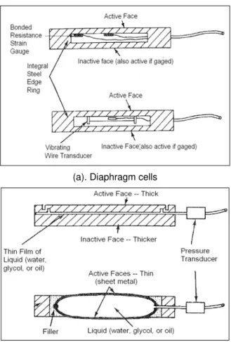
The instruments used for measuring pressure within a soil mass are called earth pressure cells, soil stress cells, or soil pressure cells. Figure 6 shows the two basic types of earth pressure cells: diaphragm cells and hydraulic cells. For the diaphragm type, the external soil pressure deflects a stiff circular membrane fully supported by an integral stiff edge ring. The deflection is sensed by an electrical resistance strain gage transducer bonded directly to the interior cell face or by a vibrating wire transducer. The hydraulic cell consists of two circular or rectangular steel plates welded together around their periphery with liquid filling the intervening cavity, and a length of high-pressure steel tubing connecting the cavity to a nearby pressure transducer. An equal pressure induced in the internal liquid balances total stress applied to the outside of the cell.
The installation of soil pressure cells can cause a change in the stress state of the soil and, thus, minimizing soil disturbance is critical. The installation of soil pressure cells for vertical measurements requires a large-diameter borehole. Drilling a large borehole and back-filling around the pressure cells is generally subject to gross conformance errors. Some success has been achieved in measuring horizontal stress: (i) in soft soils, when specially designed earth pressure cells were pushed downward into natural ground (Massarsch, 1975); (ii) in clays, when special cutting devices were used to cut a narrow slot for standard earth pressure cells along with epoxy resin used to fill the narrow clearance between the side wall of the slot and the pressure cell (Brackley and Sanders, 1992; Zhan et al., 2006).
The latter method is especially meaningful for clayey soils as the thin skin of epoxy resin adheres securely to both the cell and the soil to allow for a transmission of a tensile force between the cell and the soil. Hence, the earth pressure cells can register a tensile stress induced
by the shrinkage of expansive clays during drying. Other instruments used for this purpose include the stepped blade, the pressuremeter, and the flat plate dilatometer.
(a). Diaphragm cells
(b). Hydraulic cells
Figure 6. Earth pressure cells (Dunnicliff, 1993) Attempts to measure total stress within a soil mass are plagued by errors resulting from the difficulty of matching the elastic modulus of the pressure cell to that of a soil. It is also very hard to place the cell under field conditions (so that both faces of the cell are in intimate contact with the material) and to perform a truly representative calibration in the laboratory. Therefore, such cells are used to confirm design assumptions and to provide information for the improvement of future designs.
3.4 Temperature
The mercury thermometer, thermistor, and thermocouple are three typical temperature sensors. The mercury thermometer is useful for spot measurements at accessible locations but is fragile and not suitable for remote readout and is limited to temperature above about –30 °C.
A thermistor is composed of a thermally sensitive semiconductor material that changes its resistance markedly with changes in temperature. Lead wires are used to connect the thermistor to a measuring instrument. A thermocouple is composed of two wires of dissimilar metals with one end of each wire joined together to form a
measuring junction. At any temperature above absolute zero (-273 °C), a small voltage is generated between the wires. This voltage is proportional to the temperature of the measuring junction. The leads are connected to thermocouple readout devices.
When planning the installation of temperature sensors, care must be exercised to ensure good thermal contact between the sensors and the soils to be monitored. When installing transducers inside a borehole to measure subsurface ground temperature, the borehole must be backfilled immediately and completely, and the backfilling procedure should depend on the required measurement accuracy. When maximum accuracy is required, for example, for measuring the depth of frost penetration or when measurements are used to make decisions on limiting roadway traffic in the spring, care is required to minimize disturbance to the thermal regime and to the pathway for water movement. In such sensitive cases, an accuracy of about ±0.1 °C is required and the borehole should be backfilled with the same material removed from the borehole. The soil can be placed and tamped in layers or it can be mixed with water and poured into the borehole. When a lesser accuracy is acceptable, the borehole can be backfilled with cement grout or other material that ensures complete backfilling.
4 CONCLUSIONS
Successful instrumentation for assessing the behaviour of expansive soils must consider their unique features: periodic swelling and shrinkage, soil suction as a state variable, a high electrical conductivity, and the effect of bonded water around clay particles.
Several types of sensors can be used for field monitoring soil displacement, water content, soil presure, and temperature. Soil displacement measurement by means of the borehole installation of extensometers and inclinometers requires an intimate sensor-soil contact for accurate readings.
Water content should preferably be measured using dielectric – based sensors. Site-specific calibrations are critical for accurate representation of the water content because electric conductivity and bound water affects these sensors. For subsurface installation, the volume changes in expansive soils affect the contact between the sensors and the surrounding soils and special tools may be needed for good contact.
Thermal conductivity sensors offer a higher measurement range compared to tensiometers and can be used for long term soil suction monitoring. Both types of sensor require good contact between the porous part of the sensor and the surrounding soil. Special care is required when soil pressure cells are installed in expansive soils as any disturbance to surrounding soils may change the stress state in soils and can render the readings unrepresentative.
Thermistors and thermocouples are suitable for the field measurement of temperature. Both have wide temperature range and rapid response time. Care must be taken to ensure good thermal contact between the sensors and the soils during installation and proper backfilling procedures should be followed.
ACKNOWLEDGEMENTS
The authors are grateful for the financial support provided by the Communities of Tomorrow Inc.
REFERENCES
Annan, A.P. 1997. Time-Domain Reflectometry, Air Gap Problem for Parallel Wire Transmission Lines. Geological Survey of Canada Report of Activities, 77–1B.
Brackley, I.J.A. and Sanders, P.J. 1992. In Situ Measurement of Total Natural Horizontal Stresses in an Expansive Clay. Geotechnique, 42: 443-451. Bridge, B.J., Sabburg, J., Habash, K.O., Ball, J.A.R. and
Hancock, N.H. 1996. The Dielectric Behaviour of Clay Soils and its Application to Time Domain Reflectometry, Australian Journal of Soil Research, 34: 825-835. Dirksen, C. and Dasberg, S. 1993. Improved Calibration of
Time Domain Reflectometry for Soil Water Content Measurements. Soil Science Society of American Journal, 57: 660-667.
Dunnicliff, J. 1993. Geotechnical Instrumentation for Monitoring Field Performance, Wiley, NY.
Ferré, P.A. and Topp, G.C. 1999. Time Domain Reflectometry Techniques for Soil Water Content and Electrical Conductivity Measurements. Sensors Update, 7: 277-300.
Fredlund, D.G. 2006. Unsaturated Soil Mechanics in Engineering Practice. Journal of Geotechnical and Geoenvironmental Engineering. 132: 286-321.
Fredlund, D.G. and Rahardjo H. 1993. Soil Mechanics for Unsaturated Soils, Wiley, NY.
GCTS. 2005. SuctionData 1.12: User’s Guide and Reference, GCTS, Tempe, AZ.
Hu, Y., Vu, H. and Hubble, D. 2006. Water Content Measurements in Highly Expansive Clay Using Dielectric Based Probes. 59th Canadian Geotechnical Conference, Vancouver, BC.
Look, B.G. and Reeves, I.N. 1992. Application of
Time Domain Reflectometry in Geotechnical
Instrumentation. Geotechnical Testing Journal,
15: 277-283.
Malicki M.A., Walczak R.T., Koch, S. and Fluhler, H. 1994. Determining Soil Salinity from Simultaneous Readings of its Electrical Conductivity and Constant Using TDR. Symposium and Workshop on Time Domain Reflectometry in Environmental, Infrastruc-ture, and Mining Applications, Evanston, IL, 328–336. Massarsch, K.R. 1975. New Method for Measurement of
Lateral Earth Pressure in Cohensive Soils. Canadian Geotechnical Journal, 12:142-146.
Munoz-Carpena, R. 2004. Field Devices for Monitoring Water Content. Website http://edis.ifas.ufl.edu. Accessed May 2, 2008.
Noborio K. 2001. Measurement of Soil Water Content and Electrical Conductivity by Time Domain Reflectometry: a Review. Computers & Electronics in Agriculture, 31: 213-237.
Ponizovsky A.A., Chudinova S.M., Pachepsky Y.A. 1999. Performance of TDR Calibration Models as Affected by Soil Texture. Journal of Hydrology, 218: 35-43.
Slope Indicator. 2004. Guide to Geotechnical Instrumentation, Durham Geo Slope Indicator,
Mukilteo, WA.
SoilMoisture Equipment. 2005. 2725 Series Jet Fill Tensiometer, SoilMositure Equipment Corp., Santa Barbara, CA.
Topp, G.C., Davis, J.L. and Annan, A.P. 1980. Electromagnetic Determination of Soil Water Content: Measurements in Coaxial Transmission Lines. Water Resources Research, 16: 574-582.
Topp, G.C., Zegelin, S. and White, I. 2000. Impacts of the Real and Imaginary Components of Relative Permittivity on Time Domain Reflectometry Measurements in Soils. Soil Science Society of American Journal, 64: 1244-1252.
White, I., Knight, J.H., Zegelin, S.J. and Topp, G.C. 1994. Comments on ‘Considerations on the Use of Time-Domain Reflectometry (TDR) for Measuring Soil Water Content’ by W.R. Whalley. European Journal of Soil Science, 45: 503-508.
Zhan, T.L.T., Ng, C.W.W. and Fredlund, D.G. 2006. Instrumentation of an Unsaturated Expansive Soil Slope. Geotechnical Testing Journal, 30: 1-11.