Publisher’s version / Version de l'éditeur:
Vous avez des questions? Nous pouvons vous aider. Pour communiquer directement avec un auteur, consultez la première page de la revue dans laquelle son article a été publié afin de trouver ses coordonnées. Si vous n’arrivez pas à les repérer, communiquez avec nous à PublicationsArchive-ArchivesPublications@nrc-cnrc.gc.ca.
Questions? Contact the NRC Publications Archive team at
PublicationsArchive-ArchivesPublications@nrc-cnrc.gc.ca. If you wish to email the authors directly, please see the first page of the publication for their contact information.
https://publications-cnrc.canada.ca/fra/droits
L’accès à ce site Web et l’utilisation de son contenu sont assujettis aux conditions présentées dans le site LISEZ CES CONDITIONS ATTENTIVEMENT AVANT D’UTILISER CE SITE WEB.
Client Report (National Research Council of Canada. Construction), 2015-08-17
READ THESE TERMS AND CONDITIONS CAREFULLY BEFORE USING THIS WEBSITE.
https://nrc-publications.canada.ca/eng/copyright
NRC Publications Archive Record / Notice des Archives des publications du CNRC : https://nrc-publications.canada.ca/eng/view/object/?id=759bc23d-cf0b-4052-85c8-7975cf790a05 https://publications-cnrc.canada.ca/fra/voir/objet/?id=759bc23d-cf0b-4052-85c8-7975cf790a05 For the publisher’s version, please access the DOI link below./ Pour consulter la version de l’éditeur, utilisez le lien DOI ci-dessous.
https://doi.org/10.4224/23002857
Access and use of this website and the material on it are subject to the Terms and Conditions set forth at
Performance evaluation of proprietary drainage components and
sheathing membranes when subjected to climate loads, task 6:
hygrothermal performance of client wall assemblies for selected
Canadian locations
CONSTRUCTION
Performance Evaluation of Proprietary
Drainage Components and Sheathing
Membranes when Subjected to Climate Loads
Task 6
— Hygrothermal Performance of Client Wall
Assemblies for Selected Canadian Locations
Hamed H. Saber and Michael A. Lacasse
PERFORMANCE EVALUATION OF PROPRIETARY DRAINAGE COMPONENTS AND SHEATHING MEMBRANES REPORT A1-000030.08 i
Table of Contents
Table of Contents ... i List of Figures ... v List of Tables ... xi Acknowledgements ... xv Summary ... xvii1.0 Background and Introduction ... 1
2.0 Overview of Hygrothermal Simulation Model, hygIRC-C ... 2
2.1 Hygrothermal Simulation Model Validation ... 2
3.0 Description of Wall Assemblies & Hygrothermal Property Characterization... 3
3.1. Description of Wall Assemblies (Task 1) ... 3
3.1.1 Reference Wall Assembly ... 4
3.1.2 Client Wall Assemblies ... 6
3.2 Task 2 (Characterization of Hygrothermal Properties) ... 6
3.3 Defining Climate Loads on Wall Assembly & Drainage Systems (Task 5) ... 6
3.3.1 Weather data for hygrothermal simulation ... 6
3.4 Response of Wall Assemblies & Drainage Systems to Climate Loads (Task 5) ... 9
3.4.1. From climate loads to wind-driven rain loads acting on wall assembly and cladding ... 9
3.4.2 Water entry behind cladding due to permeation of cladding and deficiencies ... 9
3.4.3 Water retention in respective drainage systems ... 10
3.4.4 Moisture loads in drainage cavity at given storey heights ... 11
3.4.5 Distribution of moisture loads within drainage cavity ... 11
3.4.6 Other assumptions in respect to undertaking of hygrothermal simulations ... 12
Initial Conditions ... 12
4.0 Defining Performance Attributes ... 12
4.1 Locations of interest in assessing performance of wall assemblies ... 12
4.2 Performance criteria ... 12
4.2.1 RHT index ... 13
4.2.2 Mould index ... 13
Table of Contents
5.0 Results Derived from Hygrothermal Simulations ... 15
5.1 Client A Drainage System ... 15
Overview of Drainage System ... 15
Results from Simulation – Client A Drainage System ... 16
Hygrothermal response of wall components to climate loads of Tofino; MIDX criterion ... 16
Hygrothermal response of wall components to climate loads of Tofino; RHT(x) criterion ... 20
Hygrothermal response of wall components to climate loads of Vancouver; MIDX criterion ... 22
Hygrothermal response of wall components to climate loads of Vancouver (BC); RHT(x) criterion ... 26
Hygrothermal response of wall components to climate loads of St John’s NL; MIDX criterion . 26 Hygrothermal response of wall components to climate loads of St John’s, NL; RHT(x) criterion ... 30
5.2 Client B Drainage System ... 31
Overview of Drainage System – Client B ... 31
Results from Simulation – Client B Drainage System ... 33
Hygrothermal response of wall components to climate loads of Tofino and Vancouver (BC) and St John’s (NL); MIDX criterion ... 33
Hygrothermal response of wall components to climate loads of Tofino and Vancouver (BC) and St John’s, NL; RHT(x) criterion ... 37
5.3 Client C Drainage System ... 38
Overview of Drainage System – Client C ... 38
Results from Simulation – Client C Drainage System ... 40
Hygrothermal wall components response to climate loads of Tofino; MIDX criterion ... 40
Hygrothermal wall components response to climate loads of Tofino; RHT(x) criterion ... 41
Hygrothermal wall components response to climate loads of Vancouver; MIDX criterion ... 45
Hygrothermal wall components response to climate loads of Vancouver; RHT(x) criterion ... 45
Hygrothermal wall components response to climate loads of Van.; RHT(x) criterion (cont’d) . 47 Hygrothermal wall components response to climate loads of St John’s; MIDX criterion ... 49
Hygrothermal wall components response to climate loads of St John’s; RHT(x) criterion ... 51
5.4 Client D Drainage System ... 53
Overview of Drainage System ... 53
Results from Simulation – Client D Drainage System ... 55
Hygrothermal wall components response to climate loads of Tofino; MIDX criterion ... 55
Hygrothermal wall components response to climate loads of Tofino; RHT(x) criterion ... 56
Hygrothermal wall components response to climate loads of Vancouver; MIDX criterion ... 60
Hygrothermal wall components response to climate loads of Vancouver; RHT(x) criterion ... 60
Hygrothermal wall components response to climate loads of Van.; RHT(x) criterion (cont’d) . 62 Hygrothermal wall components response to climate loads of St John’s; MIDX criterion ... 64
Hygrothermal wall components response to climate loads of S. John’s; RHT(x) criterion ... 64
Hygrothermal wall components response to climate loads of St John’s (NL); RHT(x) criterion (cont’d) ... 66
PERFORMANCE EVALUATION OF PROPRIETARY DRAINAGE COMPONENTS AND SHEATHING MEMBRANES
REPORT A1-000030.08 iii
Table of Contents
5.5 Client E Drainage System ... 68
Overview of Drainage System ... 68
Results from Simulation – Client E Drainage System ... 70
Hygrothermal wall components response to climate loads of Tofino; MIDX criterion ... 70
Hygrothermal wall components response to climate loads of Tofino; RHT(x) criterion ... 73
Hygrothermal wall components response to climate loads of Vancouver; MIDX criterion ... 73
Hygrothermal wall components response to climate loads of Vancouver; RHT(x) criterion ... 77
Hygrothermal wall components response to climate loads of Vancouver; RHT(x) criterion (cont’d) ... 80
Hygrothermal wall components response to climate loads of St John’s (NL); MIDX criterion ... 80
Hygrothermal wall components response to climate loads of St. John's, NL; RHT(x) criterion 82 5.6 Client F Drainage System ... 85
Overview of Drainage System – Client F ... 85
Results from Simulation – Client F Drainage System ... 85
Hygrothermal wall components response to climate loads of Tofino & Vancouver (BC) and St John’s (NL); MIDX criterion ... 85
Hygrothermal wall components response to climate loads of Tofino & Vancouver (BC) and St John’s(NL); RHT(x) criterion ... 87
5.7 Client G Drainage System ... 91
Overview of Drainage System – Client G... 91
Results from Simulation – Client G Drainage System ... 93
Hygrothermal wall components response to climate loads of Tofino; MIDX criterion ... 93
Hygrothermal wall components response to climate loads of Tofino; RHT(x) criterion ... 96
Hygrothermal wall components response to climate loads of Vancouver; MIDX criterion ... 96
Hygrothermal wall components response to climate loads of Vancouver; RHT(x) criterion ... 99
Hygrothermal wall components response to climate loads of Vancouver; RHT(x) criterion (cont’d) ... 103
Hygrothermal wall components response to climate loads of St John’s; MIDX criterion ... 103
Hygrothermal wall components response to climate loads of St. John's; RHT(x) criterion ... 107
5.8 Client H Drainage System ... 108
Overview of Drainage System – Client H... 108
.Results from Simulation – Client H Drainage System ... 108
Hygrothermal wall components response to climate loads of Tofino & Vancouver (BC) and St John’s (NL); MIDX criterion ... 108
Hygrothermal wall components response to climate loads of Tofino & Vancouver (BC), and St John’s (NL); RHT(x) criterion ... 110
Table of Contents
5.9 Client I Drainage System ... 114
Overview of Drainage System – Client I ... 114
Hygrothermal wall component response to climate loads of Tofino; MIDX criterion ... 116
Hygrothermal wall component response to climate loads of Tofino; RHT(x) criterion ... 119
Hygrothermal wall component response to climate loads of Vancouver; MIDX criterion ... 119
Hygrothermal wall component response to climate loads of Vancouver; RHT(x) criterion .... 122
Hygrothermal wall component response to climate loads of St John’s (NL); MIDX criterion ... 126
Hygrothermal response of wall components to climate loads of St John’s; RHT(x) criterion . 128 5.10 Client J Drainage System... 131
Overview of Drainage System – Client J ... 131
Results from Simulation – Client J Drainage System ... 131
Hygrothermal response of wall components to climate loads of Tofino and Vancouver (BC) and St John’s (NL); MIDX criterion ... 131
Hygrothermal response of wall components to climate loads of Tofino and Vancouver (BC) and St John’s (NL); RHT(x) criterion ... 133
5.11 Client K Drainage System ... 137
Overview of Drainage System – Client K... 137
Results from Simulation – Client K Drainage System ... 137
Hygrothermal response of wall components to climate loads of Tofino and Vancouver (BC) and St John’s (NL); MIDX criterion ... 137
Hygrothermal response of wall components to climate loads of Tofino and Vancouver (BC) and St John’s (NL); RHT(x) criterion ... 139
6.0 Summary ... 143
Appendix 1 – List of Task Reports ... 145
PERFORMANCE EVALUATION OF PROPRIETARY DRAINAGE COMPONENTS AND SHEATHING MEMBRANES
REPORT A1-000030.08 v
List of Figures
Figure 1 – West and East coast solutions for stucco installation with capillary break ... 5 Figure 2 – NBC code-compliant reference wall - Horizontal cross section ... 5 Figure 3 – Moisture Index; Avg. WDR intensity; No. of rain events; Avg Wind pressure; Cumulative
Total WDR; Avg. outdoor t & RH (%) over 2 yrs (Avg; Wet yr.) for Tofino & Vancouver (BC), & St. John’s (NL) ... 8 Figure 4 – Client A Wall: Sectional view, placement of ML in 2 mm drainage cavity; water retention
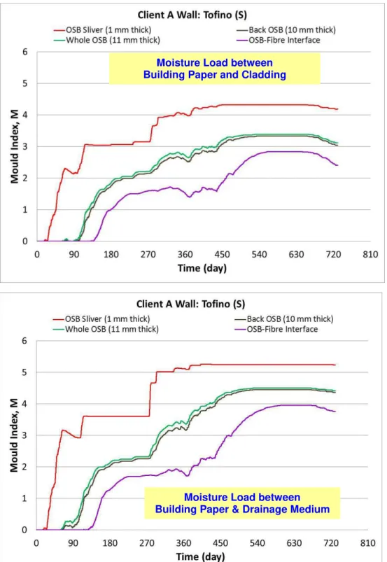
characteristic; WVP of sheathing membrane for membrane of thickness δ ... 17 Figure 5 - Client A Walls: Response of OSB component to climate loads of Tofino (BC); response given
as MIDX value for sensitivity class “S” ... 19 Figure 6 – Reference and Client A Walls: Response of OSB component to climate loads of Tofino (BC);
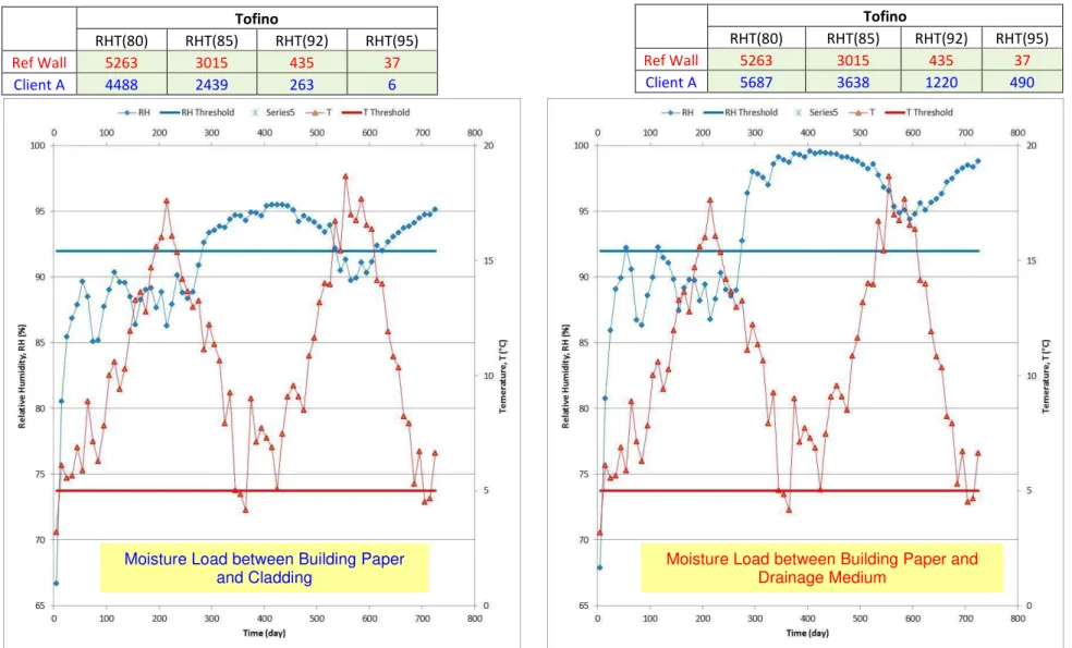
response given as MIDXvalue for sensitivity class “S”; ... 21 Figure 7 - Client A Wall: Response of OSB component (1 mm sliver on exterior surface of OSB panel) to
climate loads of Tofino (BC); response given as RHT(x) where x relates to the RH threshold value at which the index is calculated ... 22 Figure 8 - Client A Walls: Response of OSB component to climate loads of Vancouver (BC); response
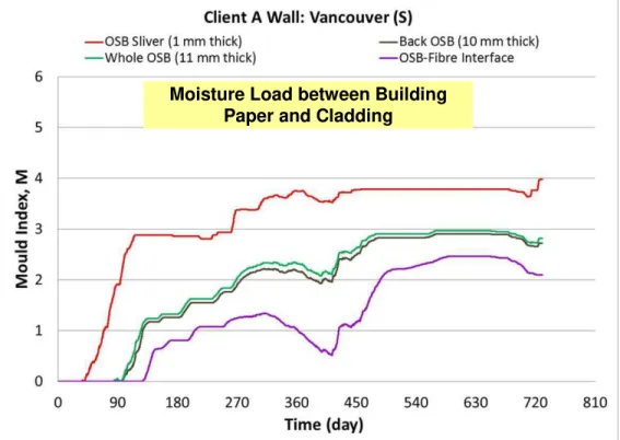
given as MIDXvalue for sensitivity class “S” ... 23 Figure 9 - Client A Walls: Response of OSB component to climate loads of Vancouver (BC); response
given as MIDXvalue for sensitivity class “S” ... 23 Figure 10 – Reference and Client A Walls: Response of OSB component to climate loads of Vancouver
(BC); response given as MIDX value for sensitivity class “S” ... 24
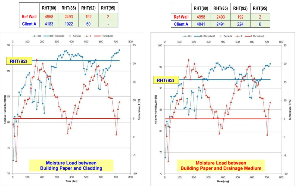
Figure 11 - Client A Wall: Response of OSB component (1 mm sliver on exterior surface of OSB panel) to climate loads of Vancouver (BC); response given as RHT(x) where x relates to the RH threshold value at which the index is calculated... 25 Figure 12 - Client A Walls: Response of OSB component to climate loads of St John’s, NF; response
given as MIDXvalue for sensitivity class “S” ... 27 Figure 13 - Client A Walls: Response of OSB component to climate loads of St John’s, NL; response
given as MIDX value for sensitivity class “S” ... 27 Figure 14 – Reference and Client A Walls: Response of OSB component to climate loads of St John’s,
NL; response given as MIDXvalue for sensitivity class “S” ... 28 Figure 15 - Client A Wall: Response of OSB component (1 mm sliver on exterior surface of OSB panel)
to climate loads of St John’s, NL; response given as RHT(x) where x relates to the RH
threshold value at which the index is provided... 29 Figure 16 – Client B Wall: Sectional view, placement of moisture load in nominal 10 mm drainage
cavity; water retention characteristics; water vapour permeance of sheathing membrane ... 32 Figure 17 – Client B Walls: Response of OSB component to climate loads of Tofino, and Vancouver
(BC) and St John’s NF; response given as MIDXvalue for sensitivity class “S” ... 34 Figure 18 – Reference and Client B Walls: Response of Gypsum component (1 mm sliver on exterior
Gypsum surface) to climate loads of (from left to right) Tofino and Vancouver (BC) and St John’s NF; response given as MIDXvalue for sensitivity class “S” ... 31
List of Figures
Figure 19 – Client B Wall: Response of Gypsum component (1 mm sliver on exterior surface of Gypsum panel) to climate loads of (from left to right) Tofino and Vancouver (BC) and St John’s NF; response given as RHT(x) where x relates to the RH threshold value at which index provided 32 Figure 20 – Client C Wall: Sectional view, placement of moisture load in nominal 10 mm drainage
cavity; water retention characteristics; water vapour permeance of sheathing membrane ... 38 Figure 21 - Client C Walls: Response of OSB component to climate loads of Tofino for ML applied
between Building Paper & Cladding; response given as MIDX value; sensitivity class “S... 42 Figure 22 - Client C Walls: Response of OSB component to climate loads of Tofino for 50% of ML
applied to sheathing membrane; response given as MIDX value; sensitivity class “S ... 42 Figure 23 – Client C Walls: Response of OSB component (1 mm sliver on exterior OSB surface) to
climate loads of Tofino (BC); response given as MIDXvalue for sensitivity class “S” ... 43
Figure 24 – Client C Wall: Response of OSB component (1 mm sliver on exterior surface of OSB panel) to climate loads of Tofino (BC); response given as RHT(x) where x relates to the RH threshold value at which the index is calculated ... 43 Figure 25 – Client C Walls: Response of OSB component to climate loads of Vancouver (BC); response
given as MIDXvalue for sensitivity class “S” ... 46 Figure 26 - Client C Walls: Response of OSB component to climate loads of Vancouver (BC); response
given as MIDXvalue for sensitivity class “S” ... 46 Figure 27 – Reference and Client C Walls: Response of OSB component to climate loads of Vancouver
(BC); response given as MIDX value; sensitivity class “S” ... 47
Figure 28 – Client C Wall: Response of OSB component (1 mm sliver on exterior surface of OSB panel) to climate loads of Vancouver (BC); response given as RHT(x) where x relates to the RH threshold value at which the index is calculated... 47 Figure 29 – Client C Walls: Response of OSB component to climate loads of St John’s (NL); response
given as MIDXvalue for sensitivity class “S” ... 50 Figure 30 – Client C Walls: Response of OSB component to climate loads of St John’s (NL); response
given as MIDX value for sensitivity class “S” ... 50 Figure 31 – Reference and Client C Walls: Response of OSB component to climate loads of St John’s
(NL); response given as MIDXvalue for sensitivity class “S” ... 51 Figure 32 - Client C Wall: Response of OSB component to climate loads of St John’s (NL); response
given as RHT(x) where x relates to the RH threshold value at which the index is calculated ... 51 Figure 33 – Client D Wall: Sectional view, placement of moisture load in nominal 10 mm drainage
cavity; water retention characteristics; water vapour permeance of sheathing membrane ... 54 Figure 34 - Client D Walls: Response of OSB component to climate loads of Tofino (BC); response
given as MIDXvalue for sensitivity class “S” ... 57 Figure 35 – Reference and Client D Walls: Response of OSB component to climate loads of Tofino (BC); response given as MIDX value for sensitivity class “S”; ... 58 Figure 36 - Client D Wall: Response of OSB component (1 mm sliver on exterior surface of OSB panel)
to climate loads of Tofino (BC); response given as RHT(x) where x relates to the RH threshold value at which the index is calculated ... 58
PERFORMANCE EVALUATION OF PROPRIETARY DRAINAGE COMPONENTS AND SHEATHING MEMBRANES
REPORT A1-000030.08 vii
List of Figures
Figure 37 - Client D Walls: Response of OSB component to ML placed between building paper & Cladding for climate loads of Vancouver; response given as MIDX value; sensitivity class “S” . 61 Figure 38 - Client D Walls: Response of OSB component to ML placed between building paper and
Cladding for climate loads of Vancouver; response given as MIDX value; sensitivity class “S” . 61 Figure 39 – Reference and Client D Walls: Response of OSB component (1 mm sliver on exterior OSB
surface) to climate loads of Vancouver; response given as MIDXvalue for sensitivity class “S” 62 Figure 40 - Client D Wall: Response of OSB component (1 mm sliver on exterior surface of OSB panel)
to climate loads of Vancouver (BC); response given as RHT(x) where x relates to the RH threshold value at which the index is calculated... 631 Figure 41 - Client D Walls: Response of OSB component to MLplaced between building paper and
Cladding for climate loads of St John’s; response given as MIDX value;sensitivity class “S” .... 65 Figure 42 - Client D Walls: Response of OSB component to Moisture Load placed between building
paper and Drainage Medium for climate loads of St John’s (NL); response given as MIDX value for sensitivity class “S” ... 65 Figure 43 – Reference and Client D Walls: Response of OSB component (1 mm sliver on exterior OSB
surface) to climate loads of St. John’s; response given as MIDXvalue for sensitivity class “S” . 66 Figure 44 Client D Wall: Response of OSB component (1 mm sliver on exterior surface of OSB panel) to climate loads of St John’s (NL); response given as RHT(x) where x relates to the RH threshold value at which the index is calculated ... 66 Figure 45 - Client E Wall: Sectional view, placement of moisture load in drainage cavity; water retention
characteristics; water vapour permeance of sheathing membrane ... 69 Figure 46 - Client E Wall: Response of OSB component to climate loads of Tofino (BC); response given
as MIDXvalue for sensitivity class “S” ... 72 Figure 47 – Reference & Client E Walls: Response of OSB to climate loads of Tofino (BC); response
given as MIDXvalue for sensitivity class “S ... 74 Figure 48 – Client E Wall: Response of OSB component (1 mm sliver on exterior surface of OSB panel)
to climate loads of Tofino (BC); response given as RHT(x) where x relates to the RH threshold value at which the index is calculated ... 75 Figure 49 Client E Wall: Response of OSB component to climate loads of Vancouver (BC); response
given as MIDXvalue for sensitivity class “S ... 76 Figure 50 – Reference & Client E Walls: Response of OSB to climate loads of Vancouver (BC); response given as MIDX value for sensitivity class “S ... 77 Figure 51 – Client E Wall: Response of OSB component (1 mm sliver on exterior surface of OSB panel)
to climate loads of Vancouver (BC); response given as RHT(x) where x relates to the RH threshold value at which the index is calculated... 78 Figure 52 - Client E Wall: Response of OSB component to climate loads of St John's, NF; response given as MIDX value for sensitivity class “S ... 81 Figure 53 – Reference & Client E Walls: Response of OSB to climate loads of St John's, NF; response
List of Figures
Figure 54 - – Client E Wall: Response of OSB component (1 mm sliver on exterior surface of OSB panel) to climate loads of St John's, NF; response given as RHT(x) where x relates to the RH threshold value at which the index is calculated ... 84 Figure 55 - Client F Wall: Sectional view; and water retention characteristics; water vapour permeance of sheathing membrane ... 86 Figure 56 - Client F Walls: Response of OSB component to climate loads of Tofino, and Vancouver (BC) and St. John’s (NL); response given as MIDXvalue for sensitivity class “S... 88 Figure 57 - Reference and Client F Walls : Response of OSB component (1 mm sliver on exterior OSB
surface) to climate loads of (from left to right) Tofino and Vancouver (BC) and St. John’s (NL); response given as MIDX value for sensitivity class “S” ... 89
Figure 58 – Client F Wall: Response of OSB component (1 mm sliver on exterior surface of OSB panel) to climate loads of (from left to right) Tofino and Vancouver and St. John’s; response given as RHT(x) where x relates to the RH threshold value at which the index is provided ... 90 Figure 59 – Client G Wall: Sectional view, placement of moisture load in nominal 10 mm drainage
cavity; water retention characteristics; water vapour permeance of sheathing membrane ... 92 Figure 60 - Client G Wall: Response of OSB component to climate loads of Tofino (BC); response given
as MIDXvalue for sensitivity class “S ... 95 Figure 61 – Reference & Client G Walls: Response of OSB to climate loads of Tofino, BC; response
given as MIDXvalue for sensitivity class “S ... 97 Figure 62 – Client G Wall: Response of OSB component (1 mm sliver on exterior surface of OSB panel)
to climate loads of Tofino (BC); response given as RHT(x) where x relates to the RH threshold value at which the index is calculated ... 98 Figure 63 - Client G Wall: Response of OSB component to climate loads of Vancouver (BC); response
given as MIDXvalue for sensitivity class “S ... 100 Figure 64 – Reference & Client G Walls: Response of OSB to climate loads of Vancouver (BC); response
given as MIDX value for sensitivity class “S ... 101 Figure 65 – Client G Wall: Response of OSB component (1 mm sliver on exterior surface of OSB panel)
to climate loads of Vancouver (BC); response given as RHT(x) where x relates to the RH threshold value at which the index is calculated... 101 Figure 66 - Client G Wall: Response of OSB component to climate loads of St John’s (NF); response
given as MIDXvalue for sensitivity class “S ... 104 Figure 67 - – Reference & Client G Walls: Response of OSB to climate loads of St John’s (NL); response given as MIDXvalue for sensitivity class “S ... 104 Figure 68 - – Client G Wall: Response of OSB component (1 mm sliver on exterior surface of OSB panel)
to climate loads of St John’s (NL); response given as RHT(x) where x relates to the RH
threshold value at which the index is calculated... 105 Figure 69 - Client H Wall: Sectional view, placement of moisture load in drainage cavity; water retention characteristics; water vapour permeance of sheathing membrane ... 109 Figure 70 - Client H Walls: Response of OSB component to climate loads of Tofino, and Vancouver
PERFORMANCE EVALUATION OF PROPRIETARY DRAINAGE COMPONENTS AND SHEATHING MEMBRANES
REPORT A1-000030.08 ix
List of Figures
Figure 71 - – Reference and Client H Walls: Response of OSB component (1 mm sliver on exterior OSB surface) to climate loads of (from left to right) Tofino and Vancouver (BC) and St John’s (NL); response given as MIDX value for sensitivity class “S” ... 112
Figure 72 – Client H Wall: Response of OSB component (1 mm sliver on exterior surface of OSB panel) to climate loads of Tofino and Vancouver (BC) and St John’s (NL); response given as RHT(x) where x relates to the RH threshold value at which the index is provided ... 1132 Figure 73 Client I Wall: Sectional view, placement of moisture load in nominal 10 mm drainage cavity;
water retention characteristics; water vapour permeance of sheathing membrane ... 115 Figure 74 - Client I Wall: Response of OSB component to climate loads of Tofino (BC); response given
as MIDX value for sensitivity class “S ... 118 Figure 75 – Reference & Client I Walls: Response of OSB to climate loads of Tofino (BC); response
given as MIDXvalue for sensitivity class “S ... 120 Figure 76 – Client I Wall: Response of OSB component (1 mm sliver on exterior surface of OSB panel)
to climate loads of Tofino (BC); response given as RHT(x) where x relates to the RH threshold value at which the index is calculated ... 121 Figure 77 Client I Wall: Response of OSB component to climate loads of Vancouver (BC); response
given as MIDXvalue for sensitivity class “S ... 123 Figure 78– Reference & Client I Walls: Response of OSB to climate loads of Vancouver (BC); response
given as MIDXvalue for sensitivity class “S ... 123 Figure 79– Client I Wall: Response of OSB component (1 mm sliver on exterior surface of OSB panel) to
climate loads of Vancouver (BC); response given as RHT(x) where x relates to the RH
threshold value at which the index is calculated... 124 Figure 80 - Client I Wall: Response of OSB component to climate loads of St John’s (NL); response
given as MIDXvalue for sensitivity class “S ... 127 Figure 81 – Reference & Client I Walls: Response of OSB to climate loads of St John’s (NL); response
given as MIDX value for sensitivity class “S ... 128 Figure 82 - Client I Wall: Response of OSB component (1 mm sliver on exterior surface of OSB panel) to
climate loads of St John’s (NL); response given as RHT(x) where x relates to the RH threshold value at which the index is calculated ... 129 Figure 83 - Client J Wall: Sectional view, placement of moisture load in nominal 10 mm drainage cavity;
water retention characteristics; water vapour permeance of sheathing membrane ... 132 Figure 84 - Client J Walls: Response of OSB component to climate loads of Tofino, and Vancouver (BC) and St John’s (NL); response given as MIDXvalue for sensitivity class “S” ... 134 Figure 85 – Reference and Client J Walls: Response of OSB component (1 mm sliver on exterior OSB
surface) to climate loads of (from left to right) Tofino and Vancouver (BC) and St John’s (NL); response given as MIDXvalue for sensitivity class “S” ... 135
Figure 86 – Client J Wall: Response of OSB component (1 mm sliver on exterior surface of OSB panel) to climate loads of Tofino and Vancouver (BC) and St John’s (NL); response given as RHT(x) where x relates to the RH threshold value at which the index is provided ... 136 Figure 87 - Client K Wall: Sectional view, placement of moisture load in nominal 10 mm drainage cavity; water retention characteristics; water vapour permeance of sheathing membrane ... 138
List of Figures
Figure 88– Client K Walls: Response of OSB component to climate loads of Tofino, and Vancouver (BC) and St John’s (NL); response given as MIDXvalue for sensitivity class “S” ... 140 Figure 89 – Reference and Client K Walls: Response of OSB component (1 mm sliver on exterior OSB
surface) to climate loads of (from left to right) Tofino and Vancouver (BC) and St John’s (NL); response given as MIDXvalue for sensitivity class “S” ... 141
Figure 90 – Client K Wall: Response of OSB component (1 mm sliver on exterior surface of OSB panel) to climate loads of Tofino and Vancouver (BC) and St John’s (NL); response given as RHT(x) where x relates to the RH threshold value at which the index is provided ... 142 Figure A91 – Hourly WDR intensity for (a) St John’s (NL), (b) Vancouver & (c) Tofino over an
PERFORMANCE EVALUATION OF PROPRIETARY DRAINAGE COMPONENTS AND SHEATHING MEMBRANES
REPORT A1-000030.08 xi
List of Tables
Table 1 – 2010 National Building Code requirements for Capillary Breaks in Coastal areas (degree-days < 3400 and
MI > 0.9, or degree days ≥ 3400 and MI > 1.0) ... 4
Table 2 – List of Wall Assemblies and Respective Characteristic Drainage Component ... 7
Table 3 –Summary of Results Obtained for Depths of Venting and Drainage Cavities ... 10
Table 4 - Description of Mould Index (M) levels [18, 19, 20] ... 14
Table 5 - Mould growth sensitivity classes and some corresponding materials [20] ... 14
Table 6 - Mould growth sensitivity classes for different materials of wall assemblies ... 14
Table 7 – Average & maximum values of MIDX for different locations in Reference (REF.) and Client A Walls; Moisture Load placed between the Building paper and: (i) Cladding; (ii) Drainage medium ... 21
Table 8 - Average and maximum values of MIDX for different locations in the Reference (REF.) and the respective walls of Client A in which the Moisture Load was placed between the Building paper and: (i) Cladding; (ii) Drainage medium ... 24
Table 9 - Response of Reference (REF.) and Client A Walls to climate loads of St John’s, NL: Average and maximum values of MIDX for different locations in walls in which the Moisture Load was placed between the Building paper and: (i) Cladding; (ii) Drainage medium ... 28
Table 10 – Response of Reference (REF.) and Client B Walls to climate loads Tofino and Vancouver (BC) and St John’s NF Average and maximum values of MIDX for different locations in walls in which Moisture Load was placed between Building paper and cladding ... 31
Table 11 – Reference and Client B Wall: Response of Gypsum component to climate loads of Tofino and Vancouver (BC) and St John’s (NL); response given as RHT(x) where x relates to the RH threshold value at which the index is provided ... 32
Table 12 – Client C Walls: Average and maximum values of MIDX for different locations of Client A in which the Moisture Load was placed between the Building paper and: (i) Cladding; (ii) Drainage medium ... 43
Table 13 – Client C Wall: Response of OSB component to climate loads of Tofino; response given as RHT(x) where x relates to the RH threshold value at which the index is calculated ... 43
Table 14 – Average and maximum values of MIDX for different locations in the Reference (REF.) and the respective walls of Client C in which the Moisture Load was placed between the Building paper and: (i) Cladding; (ii) Drainage medium ... 47
Table 15 – Client C Wall: Response of OSB component (1 mm sliver on exterior surface of OSB panel) to climate loads of Vancouver (BC); response given as RHT(x) where x relates to the RH threshold value at which the index is calculated ... 47
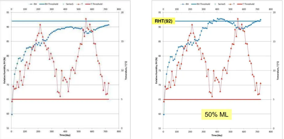
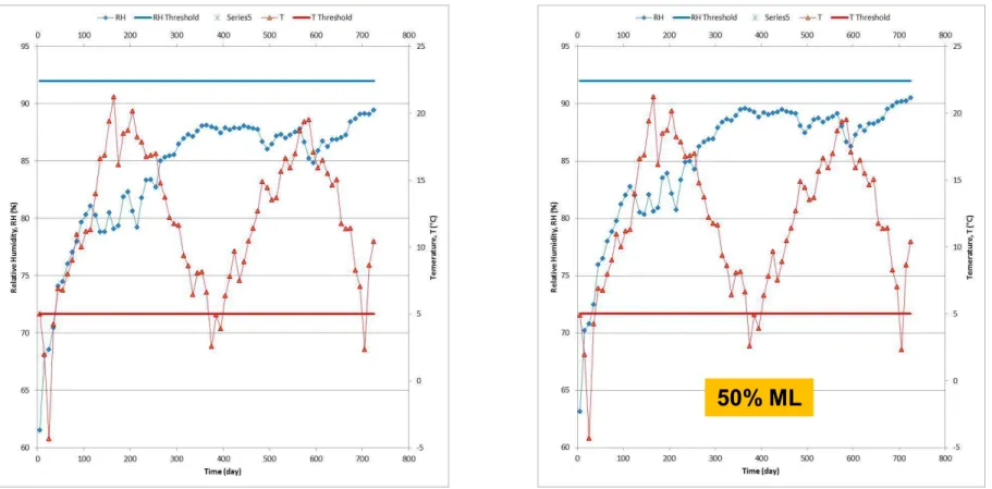
Table 16 – Response of Reference (REF) and Client C Walls to climate loads of St John’s (NL): Avg. & Max. values of MIDX for different locations in wall: ML between BP & Cladding; 50% ML on SM ... 51
Table 17 - Client C Wall: Response of OSB component (1 mm sliver on exterior surface of OSB panel) to climate loads of St John’s (NL); response given as RHT(x) where x relates to the RH threshold value at which the index is calculated ... 51
Table 18– Average & maximum values of MIDX for different locations in Reference (REF.) and Client D walls; Moisture Load placed between Building paper and: (i) Cladding; (ii) Drainage medium ... 58
Table 19 - Response of Reference & Client D Walls to climate loads of Vancouver (BC): Avg. & Max. MIDX values for locations in walls for: (i) ML between BP & Cladding; (ii) on Sheathing membrane ... 62
Table 20 – Response of Reference (REF.) and Client D Walls to climate loads of Vancouver (BC): Average and maximum values of MIDX for different locations in walls in which Moisture Load placed between Building paper and: (i) Cladding; (ii) Drainage medium ... 66
List of Tables
Table 21 – Response of Reference & Client E Walls to climate loads of Tofino (BC); Average & maximum values of MIDX for wall locations where: (i) ML* placed between building paper & Cladding; (ii) 50 % ML
on building paper; system vented; (iii) 50 % ML on building paper; system ventilated ... 74 Table 22 – Response of Reference & Client E Walls to climate loads of Tofino (BC); values of RHT(x) where x
relates to the RH threshold value at which the index is calculated where:(i) ML* placed between building paper & Cladding; (ii) 50 % ML on building paper; system vented; (iii) 50 % ML on building paper; system ventilated ... 75 Table 23 – Response of Reference & Client E Walls to climate loads of Vancouver (BC); Average & maximum
values of MIDX for wall locations where: (i) ML* placed between building paper & Cladding; (ii) 50
% ML on building paper; system vented; (iii) 50 % ML on building paper; system ventilated ... 78 Table 24 – Response of Reference & Client E Walls to climate loads of Vancouver (BC); values of RHT(x) where x
relates to the RH threshold value at which the index is calculated where:(i) ML* placed between building paper & Cladding; (ii) 50 % ML on building paper; system vented; (iii) 50 % ML on building paper; system ventilated ... 79 Table 25– Response of Reference & Client E Walls to climate loads of St John's, NF; Average & maximum values
of MIDX for wall locations where: (i) ML* placed between building paper & Cladding; (ii) 50 % ML
on building paper; system vented; (iii) 50 % ML on building paper; system ventilated ... 82 Table 26 – Response of Reference & Client E Walls to climate loads of St John's, NF; values of RHT(x) where x
relates to the RH threshold value at which the index is calculated where:(i) ML* placed between building paper & Cladding; (ii) 50 % ML on building paper; system vented; (iii) 50 % ML on building paper; system ventilated ... 83 Table 27 - – Response of Reference (REF.) and Client F Walls to climate loads Tofino and Vancouver (BC) and St
John’s (NL) Average and maximum values of MIDX for different locations in walls in which
Moisture Load was placed between Building paper and cladding ... 89 Table 28 – Reference and Client F Wall: Response of OSB component to climate loads of Tofino and Vancouver
(BC) and St John’s (NL); response given as RHT(x) where x relates to the RH threshold value at which the index is provided ... 90 Table 29 – Response of Reference & Client G Walls to climate loads of Tofino, BC (BC); Average & maximum
values of MIDX for wall locations where: (i) ML* placed between PP fabric & Cladding; (ii) 50 %
ML on building paper; system vented; (iii) 50 % ML on building paper; system ventilated... 97 Table 30 – Response of Ref. & Client G Walls to climate of Tofino (BC); values of RHT(x) where x is RH threshold
value at which index calculated: (i) ML* placed between PP fabric & cladding; (ii) 50 % ML on 2 layers of BP ; system vented; (iii) 50 % ML on 2 layers of BP; system ventilated ... 98 Table 31 – Response of Reference & Client G Walls to climate loads of Vancouver (BC); Average & maximum
values of MIDX for wall locations where: (i) ML* placed between PP fabric & Cladding; (ii) 50 %
ML on building paper; system vented; (iii) 50 % ML on building paper; system ventilated... 100 Table 32 – Response of Ref. & Client G Walls to climate loads of Vancouver (BC); values of RHT(x) where x is RH
threshold value at which index calculated: (i) ML* placed between PP fabric & cladding; (ii) 50 % ML on 2 layers of BP; system vented; (iii) 50 % ML on 2 layers of BP; system ventilated ... 101 Table 33 – Response of Reference & Client G Walls to climate loads of St John’s (NL); Average & maximum
values of MIDX for wall locations where: (i) ML* placed between PP fabric & Cladding; (ii) 50 %
ML on building paper; system vented; (iii) 50 % ML on building paper; system ventilated... 104 Table 34 - Response of Ref. & Client G Walls to climate of St John’s (NL); values of RHT(x) where x is RH
threshold value at which index calculated: (i) ML* placed between PP fabric & cladding; (ii) 50 % ML on 2 layers of BP ; system vented; (iii) 50 % ML on 2 layers of BP; system ventilated ... 105
PERFORMANCE EVALUATION OF PROPRIETARY DRAINAGE COMPONENTS AND SHEATHING MEMBRANES
REPORT A1-000030.08 xiii
List of Tables
Table 35 – Response of Reference (REF.) and Client H Walls to climate loads Tofino and Vancouver (BC) and St John’s (NL) Average and maximum values of MIDX for different locations in walls in which
Moisture Load was placed between Building paper and cladding ... 112 Table 36 – Reference and Client H Wall: Response of OSB component to climate loads of Tofino and Vancouver
(BC) and St John’s (NL); response given as RHT(x) where x relates to the RH threshold value at which the index is provided ... 113 Table 37– Response of Reference & Client I Walls to climate loads of Tofino (BC); Average & maximum values of MIDX for wall locations where: (i) ML* placed between building paper & Cladding; (ii) 50 % ML
on building paper; system vented; (iii) 50 % ML on building paper; system ventilated ... 120 Table 38 – Response of Reference & Client I Walls to climate loads of Tofino (BC); values of RHT(x) where x
relates to the RH threshold value at which the index is calculated where:(i) ML* placed between building paper & Cladding; (ii) 50 % ML on building paper; system vented; (iii) 50 % ML on building paper; system ventilated ... 121 Table 39 – Response of Reference & Client I Walls to climate loads of Vancouver (BC); Average & maximum
values of MIDX for wall locations where: (i) ML* placed between building paper & Cladding; (ii) 50
% ML on building paper; system vented; (iii) 50 % ML on building paper; system ventilated ... 124 Table 40 – Response of Reference & Client I Walls to climate loads of Vancouver (BC); values of RHT(x) where x
relates to RH threshold value at which index calculated:(i) ML* placed between BP & Cladding; (ii) 50 % ML on BP; system vented; (iii) 50 % ML on BP; system ventilated ... 125 Table 41 – Response of Reference & Client I Walls to climate loads of St John’s (NL); Average & maximum values of MIDX for wall locations where: (i) ML* placed between building paper & Cladding; (ii) 50 % ML
on building paper; system vented; (iii) 50 % ML on building paper; system ventilated ... 128 Table 42 – Response of Reference & Client I Walls to climate loads of St John’s (NL); values of RHT(x) where x
relates to the RH threshold value at which the index is calculated where:(i) ML* placed between building paper & Cladding; (ii) 50 % ML on building paper; system vented; (iii) 50 % ML on building paper; system ventilated ... 129 Table 43 – Response of Reference (REF.) and Client J Walls to climate loads Tofino and Vancouver (BC) and St
John’s (NL) Average and maximum values of MIDX for different locations in walls in which
Moisture Load was placed between Building paper and cladding ... 135 Table 44 – Reference and Client B Wall: Response of OSB component to climate loads of Tofino and Vancouver
(BC) and St John’s (NL); response given as RHT(x) where x relates to the RH threshold value at which the index is provided ... 136 Table 45– Response of Reference (REF.) and Client K Walls to climate loads Tofino and Vancouver (BC) and St
John’s (NL) Average and maximum values of MIDX for different locations in walls in which
Moisture Load was placed between Building paper and cladding ... 141 Table 46 – Reference and Client K Wall: Response of OSB component to climate loads of Tofino and Vancouver
(BC) and St John’s (NL); response given as RHT(x) where x relates to the RH threshold value at which the index is provided ... 142 Table 47 – Summary of Simulation Results of Reference and Respective Client Wall Assemblies ... 144
PERFORMANCE EVALUATION OF PROPRIETARY DRAINAGE COMPONENTS AND SHEATHING MEMBRANES
REPORT A1-000030.08 xv
Acknowledgements
The report authors wish to extend their thanks to the Air Barrier Association of American (ABAA) for having managed and arranged support for this project and in particular, to Mr. Laverne Dalgleish for his highly proficient handling of all technical and non-technical issues that arose over the course of the project. As well, acknowledgment is made of project support, technical meeting participation and the many and very useful contributions made by the respective project partners, and that included:
Benjamin Obdyke Incorporated
Canadian Concrete Masonry Producers Association Cosella-Dorken
DuPont Tyvek Weatherization Systems HAL Industries Incorporated
Home Protection Office of British Columbia – HPO Keene Building Products™
GreenGuard® Building Products (formerly Pactiv Building Products) Roxul Incorporated
STO Corporation
TYPAR® Weather Protection System (Polymer Group Incorporated)
Our thanks are also extended to our colleagues within NRC-Construction for their technical support, advice, and feedback during the course of this project and who helped support the work described in this Task report including: K. Abdulghani, M. Armstrong, S. Bundalo-Perc, S. M. Cornick, B. Di Lenardo, G. Ganapathy, W. Maref, T. Moore, P. Mukhopadhyaya, M. Nicholls, M.C. Swinton and D. Van Reenen
PERFORMANCE EVALUATION OF PROPRIETARY DRAINAGE COMPONENTS AND SHEATHING MEMBRANES
REPORT A1-000030.08 xvii
Summary
A Reference assembly and a series of 11 client wall assemblies were developed as part of the project “Performance Evaluation of Proprietary Drainage Components and Sheathing Membranes when Subjected to Climate Loads”.
The purpose of this project was to assess the performance of walls with drainage components and sheathing membranes (drainage system) in their ability to provide sufficient drainage and drying in Canadian climates with a moisture index (MI) greater than 0.9 and less than 3400 degree-days, or MI greater than 1.0 and degree days ≥ 3400 (primarily coastal areas). In these regions, the 2010 National Building Code of Canada (NBC) requires a capillary break behind all Part 9 claddings and conforming to the requirements given in § 9.27 (Cladding) of the NBC. Currently, acceptable solutions to the NBC capillary break requirement include:
(a) A drained and vented air space not less than 10 mm deep behind the cladding;
(b) An open drainage material, not less than 10 mm thick and with a cross-sectional area that is not less than 80% open, behind the cladding;
(c) A cladding loosely fastened, with an open cross section (i.e. vinyl, aluminum siding)
(d) A masonry cavity wall or masonry veneer constructed according to Section 9.20 (i.e. 25 mm vented air space)
In this project, the performance of proposed alternative solutions for the capillary break was compared through laboratory evaluation and modeling activities to the performance of a wall built to minimum NBC requirements (Reference wall assembly). The proposed drainage system would be deemed an alternative solution to the capillary break requirement in the NBC for use with current code compliant Part 9 claddings provided it exhibited better or equal moisture performance as compared to a NBC-compliant Reference wall assembly.
In This Report — Results from hygrothermal simulation have been presented in which the response of
the respective Client walls to climate conditions of Tofino and Vancouver (BC), and St. John’s (NL), have been described. The results, as provided by information on the mould index and RHT index within the assembly, permitted comparisons of the response of the respective Client walls to the Reference wall. For each of the Client wall assemblies, an overview of the Client’s drainage system was first provided to permit assessing the expected response of wall components to moisture loads within the drainage cavity, given the moisture loadings conditions and the performance attributes of the cavity, that included the size and drainage-retention response of the cavity as well as the type and water vapour permeance of the sheathing membrane used to protect the exterior surface of the OSB sheathing panel.
Thereafter, the results from simulation of the Client’s and the Reference wall are provided over a two year period to climate conditions of Tofino (BC), Vancouver (BC), and St John’s (NL). For each of these locations, results are provided using the two performance criteria; the: (i) Mould index (MIDX) criterion
(risk to mould growth), and; (ii) Relative Humidity-Temperature RHT(x) criterion (risk to the growth of wood rot fungi).
simulations and included information on:
Description of the reference wall assembly,
Description of wall assemblies in regard to their respective drainage component characteristics, Hygrothermal property characteristics,
Defining climate loads for three (3) Canadian locations,
Defining the moisture loads acting on components within the wall assembly in consideration of the amount of water entry to and drainage from wall assemblies,
Water retention in drainage systems, and
Defining performance attributes of wall components in terms of selected performance criteria including the mould index and RHT index.
PERFORMANCE EVALUATION OF PROPRIETARY DRAINAGE COMPONENTS AND SHEATHING MEMBRANES
REPORT A1-000030.08 xix
Performance Evaluation of Proprietary Drainage Components and
Sheathing Membranes when Subjected to Climate Loads
–
Task 6
– Hygrothermal Performance of Client Wall Assemblies for
Selected Canadian Locations
Authored by:
Hamed H. Saber and Michael A. Lacasse
A Report for the
AIR BARRIER ASSOCIATION OF AMERICA (ABAA)
1600 BOSTON-PROVIDENCE Highway
WAYPOLE, MA 02081
USA
ATT: Mr. Laverne Dalgleish
National Research Council Canada Ottawa ON K1A 0R6 Canada
17 August, 2015
This report may not be reproduced in whole or in part without the written consent of both the client and the National Research Council of Canada.
PERFORMANCE EVALUATION OF PROPRIETARY DRAINAGE COMPONENTS AND SHEATHING MEMBRANES
REPORT A1-000030.08 1
Performance Evaluation of Proprietary Drainage Components and
Sheathing Membranes when Subjected to Climate Loads
–
Task 6
– Hygrothermal Performance of Client Wall Assemblies for
Selected Canadian Locations
Final Report Forming Part of Task 6
Hamed H. Saber and Michael A. Lacasse
1.0 Background and Introduction
The objective of this project was to assess the hygrothermal performance of wall assemblies incorporating drainage components. More specifically, it was of interest to evaluate the ability of wall assemblies to provide sufficient moisture dissipation through the process of drainage and drying of water from these components when subjected to Canadian climates having a moisture index (MI) greater than 0.9 and less than 3400 degree-days, or MI greater than 1.0 and degree days ≥ 3400 (primarily coastal areas).
In these climates, the 2010 National Building Code of Canada (NBC) requires a capillary break behind all Part 9 claddings [1]. Currently, acceptable solutions to the NBC requirement for a capillary break
include:
a) A drained and vented air space not less than 10 mm deep behind the cladding;
b) An open drainage material, not less than 10 mm thick and with a cross-sectional area that is not less than 80% open, behind the cladding;
c) A cladding loosely fastened, with an open cross section (i.e. vinyl, aluminum siding); d) A masonry cavity wall or masonry veneer constructed according to Section 9.20 (i.e. 25 mm
vented air space).
In this project, the hygrothermal performance of proposed alternative solutions for the capillary break was compared through laboratory evaluation and modeling activities to the performance of a wall (NBC code-compliant Reference wall) built to minimum NBC requirements using the following performance criteria:
(a) RHT criterion, and;
(b) Mould index (MIDX) criterion.
If a proposed wall system incorporating a drainage component exhibited a level of performance equal to or better than the NBC-compliant Reference wall, it would be deemed an alternative solution to the 2010 NBC requirement for a capillary break and could be used with all presently recognized code compliant Part 9 claddings as acceptable solutions [1].
1
The hygrothermal performance of wall assemblies incorporating drainage components was assessed on the basis of the results obtained from numerical simulation of a NBC code-compliant Reference wall assembly when subjected to environmental loads for selected locations in Canada and conforming to interior boundary conditions as described in the ASHRAE Standard S-160 [2].
In this report, information is provided on the results from hygrothermal simulation for each of the Client (partner) wall assemblies (A to K inclusive) for mould growth sensitivity class rated as Sensitive “S”. The results for mould growth sensitivity class rated as “Medium Resistant” (MR) are provided in the companion Task 6 report A1-000030.10 [3], whereas the details of results from hygrothermal simulation of the Reference wall are given in the Task 6 report A1-000030.07 [4].
2.0
Overview of Hygrothermal Simulation Model, hygIRC-C
The NRC’s hygrothermal model, hygIRC-C was used in this project to predict the hygrothermal performance on the basis of the risk of moisture related effects within wall assemblies having different drainage components when these walls were subjected to different climatic conditions as might occur across Canada. It is important to emphasize that the predictions by such a model for the airflow,
temperature, and moisture (or relative humidity) distributions within a wall assembly, when subjected to a pressure differential (and resulting air leakage rate) across the assembly, are necessary to accurately determine the moisture response in different layers of the wall assembly.
The hygIRC-C model simultaneously solves the highly nonlinear and coupled two-dimensional and three-dimensional Heat, Air and Moisture (HAM) equations for both porous and non-porous media that define values of heat, air and moisture transfer across the various building component layers. The HAM equations were discretized using the Finite Element Method (FEM) as provided in the COMSOL Multi-physics software package that was used as a solver. The use of the FEM is important as it permits modeling complicated wall geometries with fewer discretizing errors.
A detailed description of the governing equations used in the hygrothermal model, hygIRC-C, can be found in the companion Task 6 report [4].
2.1 Hygrothermal Simulation Model Validation
The hygIRC-C model has been extensively validated in a number of other projects in which the thermal and hygrothermal performance of different systems and components of the building envelope (e.g. roofing, wall and fenestration systems) were evaluated; a review of the different projects in which the model was benchmarked is given in the Task 3 Report [4] (A1-000030.04).
Additionally in this project, two specific benchmarking exercises were conducted to verify whether proper assumptions had been made as regards the mathematical and numerical representation of physical
2
ASHRAE Standard S-160
3
See Appendix 1: List of Task Reports
4
PERFORMANCE EVALUATION OF PROPRIETARY DRAINAGE COMPONENTS AND SHEATHING MEMBRANES
REPORT A1-000030.08 3
phenomena within the hygIRC-C model and that permits capturing the hygrothermal response of components within wall assemblies; these included benchmarking the:
Moisture dissipation from a nominally saturated stucco plate conforming to NBC compliant stucco construction details when subjected to ambient laboratory conditions; the results from this work, reported in the Task 3 Report, indicated that the model correctly estimated the degree and rate of moisture dissipation over time with a variation in values of moisture content not exceeding ± 5% from that predicted by the simulation model.
Air flow through clear cavities and cavities incorporating highly porous media used as drainage components in wall assemblies; the results from these tests are provided in the Task 4 Report (A1-000030.05) [4].
o Clear Cavities — A comparison of test results to those derived from simulation showed that the majority of air velocity measurements were within the margin of uncertainty associated with the results derived from simulation for air velocity profiles obtained of cavities having depths of 10, 20 and 25 mm.
o Non-homogenous highly porous media (drainage components) — The air permeability, ��, was shown to be pressure dependent and deviations from the test values were minimized provided the value for �� was selected in relation to the pressure difference acting along the length of the cavity incorporating the drainage media. As such, values for the effective permeability coefficient, � and corresponding values for the permeability factor, F, were provided in relation to the pressure difference across the drainage components.
3.0
Description of Wall Assemblies & Hygrothermal Property
Characterization
3.1. Description of Wall Assemblies (Task 1)
The purpose of this project was to assess the performance of wall drainage components and sheathing membranes in their ability to provide sufficient drainage and drying in Canadian climates with a moisture index (MI) greater than 0.9 and less than 3400 degree-days, or MI greater than 1.0 and degree days ≥ 3400 (primarily coastal areas), as described in Table 1. In these regions, the 2010 National Building Code requires a capillary break behind all Part 9 claddings.
The approach used in this evaluation had a benchmark wall assembly against which the various client wall assemblies incorporating wall drainage components and sheathing membranes were compared in respect to their hygrothermal performance. A brief description of the benchmark wall assembly and client assemblies follows.
– 2010 National Building Code requirements for Capillary Breaks in Coastal areas (degree-days < 3400 and MI > 0.9, or degree days ≥ 3400 and MI > 1.0)
3.1.1 Reference Wall Assembly
The reference wall assembly was developed based on minimum code requirements. Stucco cladding was chosen from among the Part 9 claddings (listed in Table 1), as the “worst case scenario” for water
penetration. This selection was based on previous work at NRC on the moisture management for exterior wall systems [5], in which it was demonstrated that stucco resulted in the highest moisture load behind the primary line of protection, due to its absorptive properties, and rain penetration at cracks.
Two alternative code compliant solutions for stucco installation were considered (see Figure 1):
A solution predominantly practiced on the West Coast, with paper-backed welded wire mesh lath, and a 10 mm clear cavity;
A solution predominantly practiced on the East Coast, with expanded metal lath (no paper backing) installed on 19 mm strapping.
The East Coast solution was selected for the Reference wall assembly, and deemed to be the “worst case scenario” due to the ability for stucco to pass through the metal lath and into the drainage cavity. Unlike the West Coast solution, this East Coast wall has no layer of building paper behind the lath to reduce the possibility of stucco compromising the required clear 10 mm capillary break between the stucco cladding and back-up wall.
5
NRC, Final Report from Task 8 of MEWS Project (T8-03) - Hygrothermal Response of Exterior Wall Systems to Climate Loading: Methodology and Interpretation of Results for Stucco, EIFS, Masonry and Siding-Clad Wood-Frame Walls; Research Report, NRC Institute for Research in Construction, 2002-11-01
Coastal areas
(degree-days < 3400 and MI > 0.9, or degree days ≥ 3400 and MI > 1.0)
Sheathing
Number of Sheathing Membranes
Capillary Break Part 9 Claddings
NO Sheathing 2 10-mm vented air space (80% open) or drainage material (80% open) or Alternative Solution Lumber siding
Wood shingles & shakes
Fiber cement shingles and sheets(n/a) Plywood
OSB and waferboard Hardboard
Metal siding (horizontal or vertical) Vinyl siding (horizontal or vertical) Stucco OSB/Plywood (Installed but not required) 1 OSB/Plywood (Required and installed) 2
OSB/Plywood 1 or, 2 25-mm vented air
PERFORMANCE EVALUATION OF PROPRIETARY DRAINAGE COMPONENTS AND SHEATHING MEMBRANES
REPORT A1-000030.08 5
Figure 1 – West and East coast solutions for stucco installation with capillary break
The NBC additionally requires the wall to be vented and flashed at the bottom of the wall every 3.5 storeys. Whereas the constructed wall assemblies for lab evaluation were 1.83 m (6 ft.) in height, subsequent modeling activities took into account the performance of the full 3.5 storey assembly, including the influence of associated rain and wind loads on hygrothermal performance.
A duct penetration detail is included in the assembly drawings. Experimental work in this project examines and quantifies the potential for water to enter at a deficiency in the sealant around a duct penetration. This information is then used to determine realistic amounts of water to be introduced in the drainage and drying evaluation of the different assemblies.
A cross sectional view of the selected NBC code-compliant reference wall assembly is presented in Figure 2. Full details of the reference wall assembly and components are provided in the
Task 1 report [4].
Figure 2 – NBC code-compliant reference wall - Horizontal cross section
GALVANIZED STAPLE
INTERIOR EXTERIOR
3 COAT STUCCO
EXPANDED DIAMOND-MESH METAL LATH (NO PAPER BACKING) 19 x 38 mm WOOD STRAPPING @ 400 mm o.c. WITH AIR SPACE BUILDING PAPER CAN-CGSB 51.32
11 mm (7/16 in.) OSB SHEATHING BOARD 38 x 140 MM (2 x 6) FRAMING @ 400 mm o.c.
WITH RSI 3.5 (R20) MINERAL FIBRE BATTS 6 mil POLYETHYLENE AIR/VAPOUR BARRIER 13 mm (½ in.) GYPSUM BOARD
3.1.2 Client Wall Assemblies
Client assembly designs were based on consultations between the individual clients and
NRC-Construction; a list of client wall assemblies and their respective characteristic drainage component is provided in Table 2. Of note is that all client walls featured the same stucco cladding as the Reference wall. This cladding was chosen as a “worst case scenario”. Thus, if the drainage element of the assembly demonstrated the ability to manage the water loads introduced by the stucco cladding, it was deemed an acceptable drainage solution suitable for use with all NBC-compliant claddings, as given in Table 1. In the Task 1 report, cross sectional diagrams are provided for each wall assembly together with a table describing the elements that differ from the NBC-compliant Reference wall assembly.
3.2 Task 2 (Characterization of Hygrothermal Properties)
To carry out hygrothermal performance assessments of wall assemblies using the numerical simulation tool hygIRC-C, the hygrothermal properties of all materials used for the construction of the different wall assemblies was required as input to the model. Given that a number of the hygrothermal properties of materials of the respective wall assemblies were available in NRC’s material properties database, only the hygrothermal properties and air flow characteristics of materials that were not available were completed as part of this study.
A detailed account of the tests methods used to characterise and the resulting values obtained from tests of the hygrothermal properties of wall assembly components and air flow characteristics of the drainage components, are given in the Task 2 report (A1-000030.02) [4].
3.3
Defining Climate Loads on Wall Assembly & Drainage Systems (Task 5)
There were two primary objectives for this Task that included determining the: Climate loads to be used for testing wall assemblies;
Weather data for the hygrothermal simulation task of the project (Task 6).
The information on climate loads for testing wall configurations is summarised in the companion report to Task 6 [4] and detailed information is provided in the Task 5 report on climate loads [4].
3.3.1 Weather data for hygrothermal simulation
This portion of the task required providing the Moisture Design Reference Years (MDRYs) data for the hygrothermal simulation task of the project. After reviewing several published methods for selecting weather years for hygrothermal simulation, a small comparison study was undertaken. It was concluded that the MI MEWS method was appropriate to use for this project [6]. Rankings were produced for all the years in the climate record for each location selected. Three years, wet (maximum), average (median), and dry (minimum), were generated and converted to an acceptable format for hygrothermal analysis. Some climate information for each of these locations is provided in Figure 3 in which values are given of
6
Cornick SM, Djebbar R, Dalgliesh WA., Selecting moisture reference years using a moisture index approach. Building and Environment 2003; 38(12): 1367-1379.
PERFORMANCE EVALUATION OF PROPRIETARY DRAINAGE COMPONENTS AND SHEATHING MEMBRANES
REPORT A1-000030.08 7
Table 2 – List of Wall Assemblies and Respective Characteristic Drainage Component
Designations Description of Drainage Component
Description of component tested for
hygrothermal properties
NBC-compliant Reference wall
Air space created by 19 mm plywood strapping; on NBC
Code-compliant building paper*
NBC Code-compliant stucco
Client A Wall
Code compliant building paper* / cap fasteners provide 2 mm gap / SBPO** sheathing
membrane
SBPO sheathing membrane
Client B Wall 10 mm air space / Water repellent insulation
board (76 mm) / liquid applied membrane Water repellent insulation board
Client C Wall
Code compliant building paper* / Nylon mesh (10 mm; open matrix) / PP† nonwoven sheathing membrane
Nylon mesh (10 mm; open matrix) bonded to PP nonwoven sheathing membrane
Client D Wall
Code compliant building paper* / Cap fasteners provide 2 mm gap / Cross woven, micro-perforated polyolefin sheathing membrane with polyolefin coating
Cross woven, micro-perforated polyolefin sheathing membrane with polyolefin coating
Client E Wall
PP† fabric (stucco screen) / Dimpled HDPE‡ (11 mm) membrane / Code compliant building paper*
PP† fabric bonded to dimpled HDPE‡ membrane
Client F Wall Wall having 25 mm air space Nil (25 mm air space)
Client G Wall
Non-woven PP† fabric (stucco screen) / PP† mat (10 mm; 3-dimensional extruded PP mono-filament mesh) / Code compliant building paper*
Non-woven PP† fabric (stucco screen) / PP† mat (10 mm; 3-dimensional extruded PP mono-filament mesh) Client H Wall Porous PS
††
insulation board (52 mm) / liquid applied membrane
Porous PS†† insulation board (52 mm)
Client I Wall
2 ply, corrugated asphalt impregnated paper*; Grade D!! (3.8 mm) / Code compliant building paper*
2 ply, corrugated asphalt impregnated paper* - Grade D!!
Client J Wall
Building paper*; Grade D!!; 60 Minute / Air space created by 9.5 mm plywood
strapping / 2 layers of Code compliant building paper*
Three coat stucco with paper backed welded-wire mesh lath
Client K Wall
Building paper*, Grade D!!; 60 Minute / Air space created by 9.5 mm plywood
strapping / 2 layers of Code compliant building paper*
Three coat stucco with paper backed welded wire metal lath
* CAN-CGSB 51.32; ** SBPO – Spun bonded polyolefin; † PP – poly propylene; ‡ HDPE – high-density polyethylene; †† PS – polystyrene; !! Grade D – Building paper conforming to
US Federal specification UU-B-790a, Type 1 (barrier paper), Grade D (water-vapor permeable), Style 2 (uncreped, not reinforced, saturated).
Figure 3 – Moisture Index; Avg. WDR intensity; No. of rain events; Avg Wind pressure; Cumulative Total WDR; Avg. outdoor t & RH (%) over 2 yrs (Avg; Wet yr.) for Tofino & Vancouver (BC), & St. John’s (NL)
PERFORMANCE EVALUATION OF PROPRIETARY DRAINAGE COMPONENTS AND SHEATHING MEMBRANES
REPORT A1-000030.08 9
the: Moisture Index; Average WDR intensity; Number of rain events; Average wind pressure (Pa); Cumulative Total WDR; Average outdoor temperature (°C) and relative humidity (%).
Of these sets, hygrothermal simulations for selected locations were undertaken for an average (median), followed by a wet (maximum) year. The locations of interest were:
St. John’s (East coast climate – wet and cool, MI = 1.41); Vancouver (West coast climate – wet and mild, MI = 1.44), and; Tofino (Extreme coastal climate having MI = 3.4).
Each of these values with the exception of the moisture index which is an annual value averaged over several years, is for a 2 year period for which the first year was an average year and the second a “wet” year. This allows appreciating the significance and differences amongst the different climate loads for these three locations and to which they were subjected in simulations.
It is clearly apparent that Tofino (MI = 3.36) has the most severe climate in respect to WDR loads as the cumulative total WDR is ca. 2.5 and 3.5 times more significant (6238 kg/m2hr) than that of, respectively, St. John’s (2428 kg/m2
hr) and Vancouver (1794 kg/m2hr). This is likewise reflected in respect to the rain events for which Tofino (2833) has twice the number of events as that of St. John’s (1411) although it is the same order of magnitude and thus comparable to that of Vancouver (2362).
The average values for outdoor relative humidity over a 2-year period (Average year followed by a wet year) are all in the same order of magnitude for the three locations however, the highest value is found in Tofino (89% RH), thereafter the next highest is St. John’s (84% RH), followed by Vancouver (82% RH). Hence, for any of these coastal locations, the ability of moisture to dissipate from wetted wall assemblies is delimited by the capacity of the ambient air to absorb moisture; evidently, this is more difficult to achieve in climates having higher average relative humidifies.
A detailed description of the WDR intensities for the locations studied can be found in the companion Task 6 report [4].
3.4
Response of Wall Assemblies & Drainage Systems to Climate Loads (Task 5)
3.4.1. From climate loads to wind-driven rain loads acting on wall assembly and cladding
The scenario considered in estimating the hygrothermal response of wall assemblies and drainage systems to climate loads takes into account the wind-driven rain (WDR) and driving-rain wind pressure (DRWP) loads acting on the walls.
Detailed descriptions and the governing equations for WDR and DRWP are included in the companion Task 6 report [4].
3.4.2 Water entry behind cladding due to permeation of cladding and deficiencies
Water entry to the drainage system behind the cladding may come about due to water permeation through the cladding itself (e.g. due to cracks in the cladding), or through imperfections at the periphery of cladding penetrations such as at ventilation ducts, pipes or windows. Thus at each story, water may enter