HAL Id: hal-00299202
https://hal.archives-ouvertes.fr/hal-00299202
Submitted on 18 Oct 2004
HAL is a multi-disciplinary open access
archive for the deposit and dissemination of
sci-entific research documents, whether they are
pub-lished or not. The documents may come from
teaching and research institutions in France or
abroad, or from public or private research centers.
L’archive ouverte pluridisciplinaire HAL, est
destinée au dépôt et à la diffusion de documents
scientifiques de niveau recherche, publiés ou non,
émanant des établissements d’enseignement et de
recherche français ou étrangers, des laboratoires
publics ou privés.
Stress induced polarization currents and electromagnetic
emission from rocks and ionic crystals, accompanying
their deformation
V. Hadjicontis, C. Mavromatou, D. Ninos
To cite this version:
V. Hadjicontis, C. Mavromatou, D. Ninos. Stress induced polarization currents and electromagnetic
emission from rocks and ionic crystals, accompanying their deformation. Natural Hazards and Earth
System Science, Copernicus Publications on behalf of the European Geosciences Union, 2004, 4 (5/6),
pp.633-639. �hal-00299202�
Received: 5 July 2004 – Revised: 12 October 2004 – Accepted: 13 October 2004 – Published: 18 October 2004 Part of Special Issue “Precursory phenomena, seismic hazard evaluation and seismo-tectonic electromagnetic effects”
Abstract. A crucial question of the scientific community
nowadays, concerns the existence of electric signals preced-ing earthquakes. In order to give a plausible answer to this question, we carried out two kinds of laboratory experiments of uniaxial deformation of ionic crystals and rock samples: a) In the first kind, stress induced polarization currents are detected and recorded. Our experimental results showed not only the existence of stress induced polarization currents be-fore the fracture of the samples, but the possibility of the propagation of these signals, as well, through conductive channels, for distances much longer than the source dimen-sions. b) In the second, acoustic and electromagnetic signals are detected and recorded in the frequency range from 1 KHz to some MHz. The mechanism of generation of these signals is shown to be different for those emitted from piezoelectric and from non-piezoelectric materials.
A plausible model is also suggested, on the compatibility of our laboratory results with the processes occurring in the earth during the earthquake preparatory stage.
1 Introduction
Disturbances of the earth’s electromagnetic field, in various frequency bands, associated with imminent earthquakes are reported.
A laboratory verification concerning the existence and the propagation capability of such signals was considered nec-essary. Enough cases of laboratory experiments are reported in the literature (Enomoto and Hasimoto, 1990; Hadjicon-tis and Mavromatou, 1994; Freund, 2002; Khatiashvili and Perelman, 1989; Mogi, 1962; Nitsan, 1977; Ogawa et al., 1985; Yamada et al., 1982; Warwick, 1982). Although vari-ous aspects, that satisfactorily explain the generation mech-anisms of an earthquake, have been suggested so far, it can-not be maintained that the special conditions and processes
Correspondence to: V. Hadjicontis
that prevail during the earthquake preparation stage are com-pletely clarified. However, from the physical point of view, it is obligatory that the stress variations in the focal area should follow the next procedure before the main shock: The stress gradually increases, (static frictional stress), until it reaches a critical maximum value (unstable situation) resulting to the microfracturing unstable situation. During this stage, mi-crofracturing acceleration occurs and intense acoustic and electromagnetic emission is detected, which becomes even more intense as the final failure is approached. This critical phenomenon lasts for a certain time and leads to the fracture followed by the stress dropping abruptly. New discoveries suggested that a microfracturing process evolution might dis-play criticality or self-organized criticality (Chunshenk et al., 1999; Garmen et al., 2001; Garshimartin et al., 1997; Kapiris et al., 2003; Varotsos et al., 2002).
In the present work, we carried out experiments of uni-axial compression of dry granite samples and ionic crystals LiF, with high electric resistivity. Some of the samples, as granite, include piezoelectric material, and some others do not have piezoelectric properties, as the ionic crystals (LiF). In the first part of this paper the laboratory experiments lead-ing to the detection of stress induced polarization currents are presented, while in the second part, the lab. experiments lead-ing to the detection of acoustic and electromagnetic emission are displayed.
2 Stress induced polarization currents
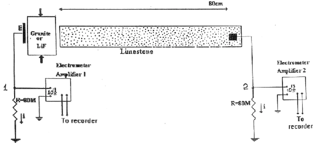
Concerning the detection of stress induced polarization cur-rents, the experimental apparatus consists of the uniaxial compression loading machine and a system for the electric measurements (Fig. 1). The electric signals emitted by a compressed sample can be detected via a probing electrode E which is a copper plate with dimensions 1×1 cm2, grounded through a resistance R of the order of some tens M. This probing electrode E is placed in parallel and very close to the sample’s surface (at ≈0.5 mm), and has effective capacity
634 V. Hadjicontis et al.: Stress induced polarization currents and electromagnetic emission
Fig. 1. Experimental configuration, for the detection of stress induced polarization currents, emitted during the uniaxial compression of the
crystalline samples and prior to their fracture.
Fig. 2. Stress induced polarization currents from LiF detected via a
probing electrode placed close to the sample. Note the threshold at the stress curve for the initiation of the signal emission.
with respect to the ground. The sample’s dimensions are ap-proximately 2×2×3 cm3. Due to the electrostatic nature of the potential measurements a single ended electrometer am-plifier with high input resistance (≈1013) was connected with the probing electrode E. The variations of the mechani-cal load are measured by a load-cell, with its own amplifier. The output of the electrometer amplifier and the load cell are simultaneously recorded by the memory recorder HIOKI 8185. It should be mentioned that the entire experimental setup as well as the manipulator are in an earthed shielded room (Faraday cage), made of copper foil, in order to elim-inate the electric noise. For the same reason, the loading machine is hand operated and not motorized.
During the experiment, the following manipulations were followed: The externally applied mechanical load increases, with approximately constant rate, from an initial value to a final one. Care must be provided so that the final stress value does not exceed the critical one when the microfracturing process starts. During the stress changes, and because of the
variations of the sample’s polarization, transient currents are detected. A representative example concerning the detection of stress induced polarization currents from LiF via an elec-trode placed very close to the sample is depicted in Fig. 2. The experimental configuration shown in Fig. 1 could help us understanding the origin of stress induced polarization cur-rents. As the stress changes, charge separation occurs in the bulk of the high resistivity dielectric sample, resulting in the macroscopic polarization of the sample and thus in the vari-ation of the electric field around the sample. Consequently the potential of the probing electrode E temporarily changes (with reference to the ground). In order to compensate this potential difference, between the electrode E and the ground, charges flow from the earth towards the electrode or vice-versa, through the resistance R. This transient phenomenon is characterized by a relaxation time which depends on R. The range of the R values (some tens of M, substantially lower than that of the imput resistance of the electrometer amplifier 1013) is carefully selected so as the aforementioned relax-ation time is comparable to the rate of the stress changes. It should be mentioned that the recombination rate of the sam-ple’s separated charges is clearly larger than the stress vari-ations rate. As far as the origin of the sample’s electric po-larization (due to the stress variations) is concerned, it could be attributed either to the well known piezoelectric effect, if the sample has piezoelectric properties (granite, quartzite), or to the movements of segments of charged dislocations with respect to their compensating Debye-H¨uckel cloud of point defects, if the sample is not piezoelectric, (pure LiF) (Hadji-contis and Mavromatou, 1994). We must take under consid-eration that the stress field within the sample is inhomoge-neous.
We repeated the experiment by placing a copper plate, serving as electrode, at some distance from the sample, e.g. 80 cm, in the air, and found no signal. In order to check the possibility of using a coupling media which could serve as wave guide, we repeated the experiment by placing a limestone rod with 80 cm length, in conditions of ambient
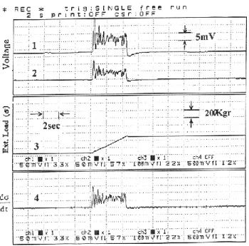
Fig. 3. Stress induced polarization currents recorded
simultane-ously via the probing electrode which is close to the compressed granite sample, (curve1), and via the electrode painted with con-ductive paint on the limestone rod (curve 2). Curve 3 depicts the mechanical load exerted on the sample and curve 4 depicts the first time derivative of the mechanical load.
humidity. (The same experiment was repeated with rods made of various kinds of rocks). As shown in Fig. 1, one end of the rod is very close to the compressed sample, (a granite sample), and on the other end an electrode is painted with silver paint. Stress induced polarization currents can be detected by the far end electrode, as depicted in Fig. 3. The experimental results depicted in Fig. 3 lead to the conclusions below:
1. The two signals are very similar in the form but they (in general) differ in amplitude.
2. The electric signals follow the first time derivative of the stress variations.
3. The higher frequency variations appearing in the stress derivative, and therefore to the electric signals, can be attributed to the stress fluctuations due to the inhomo-geneities of the sample’s structure.
The rock rod is the medium through which the electromag-netic coupling is achieved, so as the signals are induced and can be detected far from the sample. It acts as a conduc-tive channel through which the disturbances stimulated by the stress variations on the compressed sample are induced. The induction mechanism, which is responsible for the chan-neling of the potential disturbances, could be possibly at-tributed to the diffusion of charges in the bulk of the rod, due to the electrolytic conductivity. The presence of humid-ity and therefore the presence of mobile ion charge carriers,
Fig. 4. A pattern for the propagation of the stress induced
polariza-tion currents through the earth’s crust.
should be taken under consideration. On the contrary, if the rod becomes completely dry, experiments showed that the induced electric currents cannot propagate).
The aforementioned experimental results indicate that, when a high resistivity dielectric material undergoes stress variations prior to its fracture, the stimulated transient polar-ization currents (of the order of some nA/cm2), can be also measured at a distance of many times longer than the sam-ple’s dimensions after being propagated through the coupling of a suitable rock channel.
At this point a crucial question arises: Can the tectonic processes that precede earthquakes induce on the earth’s sur-face such electric signals before earthquakes?
Electrification phenomena similar to those observed dur-ing the laboratory experiments possibly occur, in a large scale, in the earth’s lithosphere, during the earthquake’s preparation process. In the depth of some tens of km, where the hypocenters of the shallow earthquakes occur, the litho-sphere is supposed to consist of crystalline rock mass, hav-ing dielectric properties. Durhav-ing the stress changes on the focal area, and prior to fracture (in other words prior to earthquake) extended charge separation occurs in the dielec-tric crystalline block, and hence local elecdielec-tric fields are pro-duced. Due to the fact that the stress has a preferential orien-tation, in tectonic processes, the superposition of local fields gives rise to an electric field in a macroscopic scale. The potential disturbances, resulting from this large scale polar-ization, stimulates perturbation of charges in more conduc-tive rocks close to the focal area, being formerly in electro-static balance. This charge perturbation propagates through conductive paths, connecting the focal area with the earth’s surface, and can disturb the electrostatic balance of the free charges, which are distributed in the earth’s conductive sur-face layer. During the redistribution of the sursur-face charges of the earth, transient electric currents flow in “sensitive” parts of the earth’s surface. Figure 4 depicts an approximation of the aforementioned model.
636 V. Hadjicontis et al.: Stress induced polarization currents and electromagnetic emission
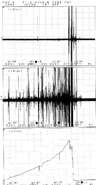
Fig. 5. Compression of a non-irradiated LiF crystal. Upper: A
time series of electromagnetic emission Middle: A time series of acoustic emission Lower: Stress variations, till the final failure of the LiF sample.
3 Acoustic and electromagnetic emission
Concerning the detection of acoustic and electromagnetic emission an appropriate experimental set-up has been de-veloped, consisting of two parts: one for low sampling rate recordings and one for high sampling rate recordings (up to 10 Msamples /sec) (Ninos et al., 2004).
The most important results as far as the acoustic and elec-tromagnetic emission are concerned, are the following:
1. During the sample’s compression and till its final fail-ure, acoustic and electromagnetic time-series are de-tected (with low sampling rate). Figures 5 and 6. The
Fig. 6. Part of a time series for electromagnetic (upper) and acoustic
(lower) emission for a granite sample.
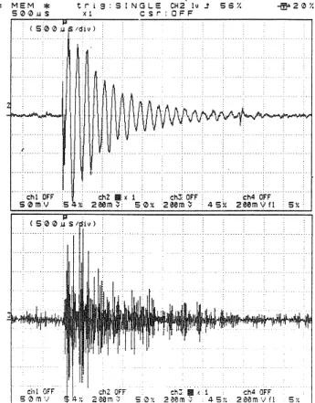
Fig. 7. A microcracking event stimulates electric and elastic
damp-ing oscillations in a granite sample, due to the piezoelectric effect. (upper): Electric oscillation deriving from an individual microc-rack. (lower): Elastic oscillation (acoustic emission) deriving from an individual microcrack.
frequency band of these signals is in the range of 1 KHz to some MHz.
2. Using a transient recorder and after appropriate trig-gering, individual acoustic and electromagnetic events of very short duration were captured and recorded, in a high sampling rate, corresponding to the same
Fig. 8. Microfaulting event in compressed LiF crystal (non-piezoelectric material). (upper): The emitted electromagnetic pulse. (lower): The corresponding elastic wave deriving from the elastic energy release. Note the time delay for the onset of the two events.
microfracture event. This is shown in Fig. 7 for granite, and in Fig. 8 for LiF. The results shown in the aforemen-tioned figures reveal that the mechanisms to which the emission of the electromagnetic signals can be possibly attributed to, are different for LiF and granite.
(a) Granite is a complex material containing quartz in-clusions, which is a well known piezoelectric mate-rial. The quartz grains are connected among each other with a non piezoelectric and not so brittle material. When the stress exceeds a certain value of strength, then in the not so brittle material that surrounds the quartz grains microfracturing events occur. The elastic waves originating from the mi-crofracturing process stimulate damping electric vi-brations of the quartz grains, which are polarized due to high stress. The frequencies of the emit-ted signals correspond to the normal modes of the quartz grains. Figure 7 depicts this experimental result for a granite sample.
(b) LiF is not a piezoelectric material. Upon deforma-tion, and after the piling up of moving segments of charged dislocation and the resulting hardening, microcracks are formatted, which bear two freshly cut charged surfaces. The abrupt acceleration of the
Fig. 9. Compression of a LiF crystal irradiated with Co60, (dose 6 Mrad) (Upper): The electromagnetic emission substantially de-creased. (middle): The acoustic emission remains strong. (lower): Stress variations from the beginning of the compression till the final failure.
charge dipole moment due to the dynamical situa-tion of microcrack opening, results in an electro-magnetic pulse emission. The corresponding tic wave derives from the sudden release of the elas-tic energy during a microcrack opening. It is de-tected with a delay in its arrival time (in reference to the EM pulse) due to the different propagation velocities. Figure 8 depicts this experimental re-sult. It is interesting to see that in Fig. 8 the gen-erated mechanical wave consists of different modes corresponding to transversal and longitudinal vol-ume waves and surface waves with different prop-agation velocities and hence with different arrival
638 V. Hadjicontis et al.: Stress induced polarization currents and electromagnetic emission
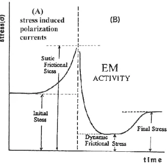
Fig. 10. Stress versus time on a surface of a propagating shear
frac-ture in the focal area according to Kasahara (page 139, 1981).
times (Kulhanek, 1990). The elastic wave emitted from a microfaulting looks like a minor quake in the sample’s bulk.
As a conclusion we can say that the mechanism for the emis-sion of electromagnetic disturbances for LiF, is different that that for granite containing piezomaterial. In order to sup-port this hypothesis, we carried out the following experi-ment: We irradiated LiF crystals with Co 60 with irradia-tion doses up to 10 Mrad. These γ -irradiated crystals were then compressed and we found out that the electromagnetic emission was drastically decreased, during the various stages of compression, until close to the final failure. On the con-trary, acoustic emission remains strong. This is shown in Fig. 9, for irradiation dose 6 Mrad. Furthermore, as the irra-diation dose increases, the electromagnetic emission drasti-cally decreases. The aforementioned laboratory result is at-tributed to the creation of F-centers after irradiation (Nadeau, 1962) which trap the electric charges created on the fresh microcrack surfaces. Our experiments with irradiated gran-ite samples showed that the aforementioned experimental re-sult does not hold for the piezoelectric materials, as granite. Therefore we conclude that the mechanism for the emission of electromagnetic pulses from ionic crystals is different than the mechanism for the emission of electromagnetic pulses from piezoelectric materials.
4 Concluding remarks
In order to investigate the compatibility of our experimental results with the processes occurring in the earth during the earthquake preparatory stage, we should carefully consider Figs. 4 and 10 in conjunction. Let us consider a fault
ter-minating on an unruptured basement rock F, as depicts the pattern in Fig. 4, through which the fault will further prop-agate, after being activated. During the preparation of an earthquake (associated to faulting), two stages can be distguished: a) The shear stress on the unruptured rock mass in-creases (d2σ/dt2>0) but the opposite fault sides do not move yet (static friction) (Fig. 10, left). In this stage, according to our experimental results, suitable conditions exist for the emission of stress induced polarization currents. b) When the stress on the unpuptured basement rock reaches the yield point, the microfracturing process starts. This process con-secutively leads to the critical situation of fragmentation and failure of the focal area F. This is a suitable condition for the initiation of the EM emission, which becomes stronger as approaching total failure, (Fig. 10, right).
Once the fragmentation and total failure of the F area is completed, the EM emission stops, the “breaks” that keep the two opposite parts of the fault cease, therefore the two chunks slide past each other. This might explain the fact that during the sliding (earthquake) no EM emission is observed.
Acknowledgements. This paper was prepared in the frame of the
“Kapodistrias” project, University of Athens. Authors would like to thank the anonymous referees for their useful suggestions. Edited by: P. F. Biagi
Reviewed by: two referees
References
Chunshenk, L., Vere-Jones, D., and Takayasu, H.: Avalanche be-haviour and statistical properties in a microcrack coalescence process, Phys. Rev. Lett., 82, 2, 347–350, 1999.
Enomoto, Y. and Hashimoto, H.: Emission of charged particlesfrom indentation fracture of rocks, Nature, 346, 6285, 641–643, 1990. Freund, F.: Charge generation and propagation in igneous rocks, J.
Geodyn., 33, 543–570, 2002.
Garsimartin, A., Guarino, A., Bellon, L., and Ciliberto, C.: Statis-tical properties of fracture precursors, Phys. Rev. Lett., 79, 17, 3202–3205, 1997.
Garmen, M., Vespignani, A., Zappeti, S., Weiss, J., and Grasso, J. R.: Intermittent dislocation flow in viscoplastic deformation, Nature, 410, 667–671, 2001.
Hadjicontis, V. and Mavromatou, C.: Transient electric signals prior to rock failure under uniaxial compression, Geophys. Res. Lett. 21, 1687–1691 , 1994.
Kapiris, P., Eftaxias, K., Nomikos, D., Polygiannakis, J., Dologlou, E., Balasis, G., Bogris, N., Peratzakis, A., and Hadjicontis, V.: Evolving towards a critical point: A plausible electromagnetic way in which the critical regime is reached as the rupture ap-proaches, Nonlin. Proc. Geophys., 10, 511–524, 2003,
SRef-ID: 1607-7946/npg/2003-10-511.
Kasahara, K.: Earthquake Mechanics, University press, Cambridge, 1981.
Khatiashvili, N. and Perelmann, M.: On the mechanism of seismo-electromagnetic phenomena and their possible role in the EM radiation during periods of earthquakes, foreshocks and after-shocks, Phys. Earth Plan. Inter., 57, 169–177, 1989.
Kulhanek, O.: Anatomy of seismograms, Developments in Solid Earth Geophysics, 18, Elsevier, 1990.