DYNAMIC ANALYSIS OF ASTRONAUT MOTIONS
DURING EXTRAVEHICULAR ACTIVITY
by
Grant Schaffner
SUBMITTED TO THE DEPARTMENT OF AERONAUTICS AND ASTRONAUTICS IN PARTIAL FULFILLMENT OF THE REQUIREMENTS
FOR THE DEGREE OF
MASTER OF SCIENCE
at the
MASSACHUSETTS INSTITUTE OF TECHNOLOGY
June 1995
Copyright @ Massachusetts Institute of Technology, 1995. All rights reserved.
Signature of Author
Certified by
Accepted by
/7
Depient o ronautics and Astronautics May 18, 1995Professor Dava J. Newman Thesis Supervisor
V Professor Harold Y. Wachman Chairman, Department Graduate Committee
MASSACHUSETTS INSTITUTE
OJ -rrnUnl n9y
JUL 07 1995
L-4hArllcr-DYNAMIC ANALYSIS OF ASTRONAUT MOTIONS DURING EXTRAVEHICULAR ACTIVITY
by
Grant Schaffner
Submitted to the Department of Aeronautics and Astronautics on May 22, 1995 in partial fulfillment of the requirements for the Degree of Master of Science in
Aeronautics and Astronautics. Abstract
Simulation of astronaut motions during extravehicular activity (EVA) tasks was performed using computational multibody dynamics methods. The application of computational dynamic simulation to EVA was prompted by the realization that physical microgravity simulators have inherent limitations: viscosity in neutral buoyancy tanks;
friction in air bearing floors; short duration for parabolic aircraft; and inertia and friction in suspension mechanisms. These limitations can mask critical dynamic effects that later cause problems during actual EVAs performed in space.
Methods of formulating dynamic equations of motion for multibody systems are discussed with emphasis on Kane's method, which forms the basis of the simulations presented herein. Formulation of the equations of motion for a two degree of freedom arm is presented as an explicit example. The four basic steps in creating the computational simulations were: system description, in which the geometry, mass properties, and interconnection of system bodies are input to the computer; equation
formulation based on the system description; inverse kinematics, in which the angles,
velocities, and accelerations of joints are calculated for prescribed motion of the endpoint (hand) of the arm; and inverse dynamics, in which joint torques are calculated for a prescribed motion. A graphical animation and data plotting program, EVADS (EVA Dynamics Simulation), was developed and used to analyze the results of the simulations that were performed on a Silicon Graphics Indigo2 computer.
EVA tasks involving manipulation of the Spartan 204 free flying astronomy payload, as performed during Space Shuttle mission STS-63 (February 1995), served as the subject for two dynamic simulations. An EVA crewmember was modeled as a seven segment system with an eighth segment representing the massive payload attached to the hand. For both simulations, the initial configuration of the lower body (trunk, upper leg, and lower leg) was a neutral microgravity posture. In the first simulation, the payload was manipulated around a circular trajectory of 0.15 m radius in 10 seconds. It was found that the wrist joint theoretically exceeded its ulnal deviation limit by as much as 49.80 and was required to exert torques as high as 26 N-m to accomplish the task, well in excess of the wrist physiological limit of 12 m. The largest torque in the first simulation, 52 N-m, occurred in the ankle joint. To avoid these problems, the second simulation placed the arm in a more comfortable initial position and the radius and speed of the circular trajectory were reduced by half. As a result, the joint angles and torques were reduced to values well within their physiological limits. In particular, the maximum wrist torque for the second simulation was only 3 N-m and the maximum ankle torque was only 6 N-m.
Thesis Supervisor: Dr. Dava J. Newman
Biographical Note
Grant Schaffner was born in Nigel, South Africa on 31 December 1965. At present, he is a permanent resident of the United States. He received his Bachelor of Science degree from the Massachusetts Institute of Technology in June 1989. Following this, he worked at Payload Systems Inc. in Cambridge, Massachusetts for two years on hardware design and development for spaceflight experiments performed on the Space Shuttle and Mir space station. Before returning to MIT to pursue graduate study, he spent two years at Space Industries, Inc., in League City, Texas where he worked on the Wakeshield Facility, COMET spacecraft, and advance engineering studies. He is currently studying jointly in the MIT Department of Aeronautics and Astronautics and the Harvard-MIT Medical Engineering Medical Physics Program. He is a member of the EFT, TBH, and Y-honor societies.
Acknowledgements
This research was sponsored by NASA grant NAGW-4336 and NASA contract NAS 1-18690.
I would like to thank Professor Dava Newman for her guidance and kindness over the past two years and for the many hours she devoted to editing this thesis. Her enthusiasm and sense of humor provide much encouragement, particularly after an all-nighter. Much thanks to David Rahn for all the effort he put into developing EVADS and for all his computer graphics wizardry, especially in light of his heavy course load. Steve Robinson, now living out his dream of becoming an astronaut, was a tremendous help in performing the Intelsat VI simulation. Also, much appreciation goes to Dr. Chuck Oman and Professor Larry Young for allowing me to be part of the MIT Man-Vehicle laboratory. Mike Sherman and Dan Rosenthal at Symbolic Dynamics, Inc. were lifesavers. Without their assistance in learning to use SD/FAST, and their great patience during many telephone calls, the Spartan simulations could not have been done.
There are many people at NASA that I would like to thank: Cab Callaway for his enthusiasm, his belief in our research goals, and his assistance in finding funding; Dr. Harry Holloway for his generous support; Jim Maida and Abilash Pandya for the use of the NASA human strength model; Cal Seaman for EVA data and much other help; Dr. Jeff Hoffman for his encouragement and ideas; and Jerry Miller for his support.
At the MIT Artificial Intelligence Laboratory, I wish to thank Prof. Raibert, Rob Playter, and Robert Ringrose who kindly allowed us to use their Creature Library program to perform the Intelsat dynamic simulation.
At Musculographics, Inc., thanks go to Dwight Meglan, for the copy of his PhD dissertation and other assistance during the early stages of my research, and Peter Loan for granting us the rights to use SIMM as a beta test site.
To all my friends, thanks for making these two years as enjoyable as they were productive. In particular, I must thank, Zsuzsanna, for rescuing my sanity during the doctoral qualifying exams, and Karl and Jennifer for providing much comic relief during the final exhausting weeks of thesis completion. Also Dave, Jeni, Keoki, Steve, Lois, Scott, Allison, Nikolai, Rob, Jason, Yanni, Jurgen, Laura, Matt, Nikol, Amy, Liz, my many new ISU friends, and all the highly skilled soccer players of the MIT Graduate Soccer Club.
Finally, a great deal of thanks goes to my mother and father for their unfailing support and encouragement over the years and over the distance, and to my whole family for the warm welcomes received during the all too seldom trips back home to South Africa.
Freedom Day, South Africa
28 April 1994
I have fought against white domination, and I have fought against black domination.
I have cherished the ideal of a democratic and free society in which all persons live together in harmony and with equal opportunities. It is an ideal which I hope to live for and to achieve. But if needs be, it is an ideal for which I am prepared to die.
-Nelson Mandela, spoken from the dock in 1964, before being sentenced to life imprisonment on Robben Island.
Never, never, and never again shall it be that this beautiful land
will again experience
the oppression of one by another...
-Nelson Mandela, during his South African Presidential Inauguration speech. May 10, 1994.
Table of Contents
Biographical Note ... Acknowledgements ... ... 4 Table of Contents ... 6 List of Figures ... 8... List of Tables ... 9...List of Acronyms and Abbreviations ... ... 10
1. Introduction ... 11
1.1 Description of Extravehicular Activity ... 11
1.2 Motivation ... 12
1.3 Objectives and Contribution ... 14
1.4 Synopsis of Thesis ... .. 15
2. Background ... 17
2.1 A Brief History of EVA ... 18
2.2 The Space Environment and EVA ... 20
2.3 Spacesuit Requirements and Implications ... 22
2.4 Training and Physical Simulators ... 24
2.4.1 Neutral Buoyancy Tanks ... 24
2.4.2 Air Bearing Floors ... 27
2.4.3 Aircraft Flying Parabolic Trajectories ... 29
2.4.4 Suspension Mechanisms ... 31
2.4.5 Synopsis of Physical Simulators ... 33
2.5 Computational Simulation of Multibody Dynamics ... 33
2.5.1 Formulation of Dynamical Equations and Simulation Methods ... ... 36
2.5.2 Kane's Dynamical Equations, AUTOLEV and SD/FAST ... 40
2.5.3 Intelsat VI Capture Mission Simulation ... 45
2.5.4 Limitations and Challenges of Computational Simulation... 56
3. Methodology ... 59
3.1 Example of Dynamical Equation Formulation ... 59
3.1.1 Lagrangian Formulation ... 60
3.1.2 Equations of Motion for a Two Degree of Freedom Arm... 63
3.2 STS-63 Spartan Mass Handling EVA Task ... 64
3.3 Simulation Objectives ... 67
3.4 Dynamic Simulation ... 69
3.4.1 System Description ... ... 69
3.4.2 Formulation of Equations of Motion ... 75
3.4.3 Joint Torque Test Functions ... 76
3.4.4 Inverse Kinematics ... 78
3.4.5 Inverse Dynamics... .. 81
3.5 Comparison with Physiological Limits ... ... ... 82
3.6 Animation and Data Display ... ... ... .... ... 82
4. R esults ... ... 84
4.1 Joint Torque Test Functions ... ... ... 84
4.2 Simulation No. 1 -Fixed Lower Body ... 85
4.2.1 Inverse Kinematics (No. 1 -Fixed Lower Body) ... 88
4.2.2 Inverse Dynamics (No. 1 -Fixed Lower Body) ... 94
4.3 Simulation No. 2 -Compliant Lower Body ... . 96
4.3.1 Inverse Kinematics (No. 2 -Compliant Lower Body)... 100
4.3.2 Inverse Dynamics (No. 2 -Compliant Lower Body) ... 106
4.4 Animation and Data Display ... 108
5. Discussion and Conclusions ... 112
5.1 First Simulation -Fixed Lower Body ... 113
5.2 Second Simulation -Compliant Lower Body ... 114
5.3 EVADS Computer Program ... 115
5.4 Conclusions ... 115
5.5 Recommended Future Research ... 118
5.6 Summary Paragraph ... 121
References... 122
Appendix A -System Description File ... 126
List of Figures
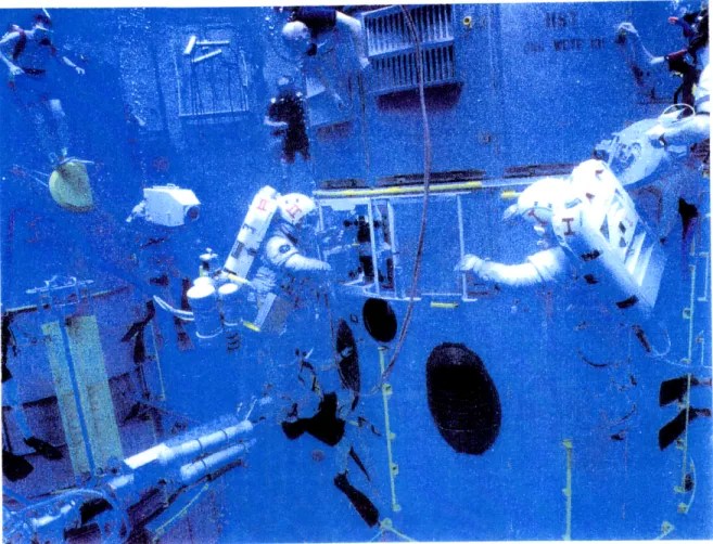
Figure 2.1 Astronauts during EVA training in the Neutral Buoyancy Facility at
M arshall Space Flight Center ... 26
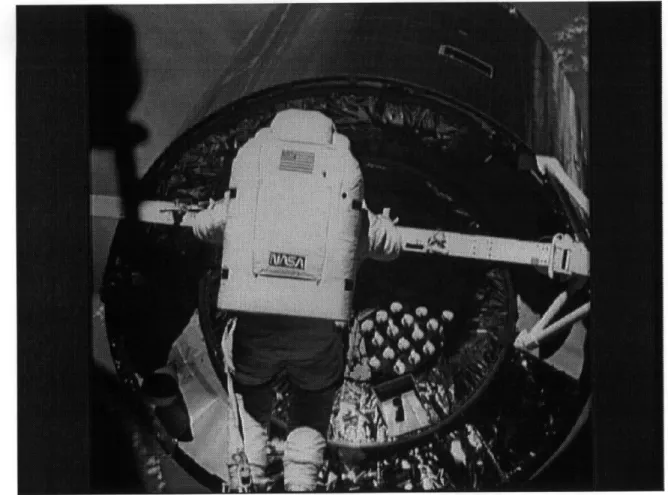
Figure 2.2 Spacesuited astronaut conducting a test on an air bearing floor ... 28
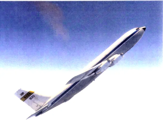
Figure 2.3 NASA KC-135 "Zero-g" aircraft entering a weightlessness parabola. ... 30
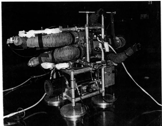
Figure 2.4 POGO suspension mechanism at NASA's Johnson Space Center. ... 32
Figure 2.5 Topological terms applied to multibody dynamic systems. ... 34
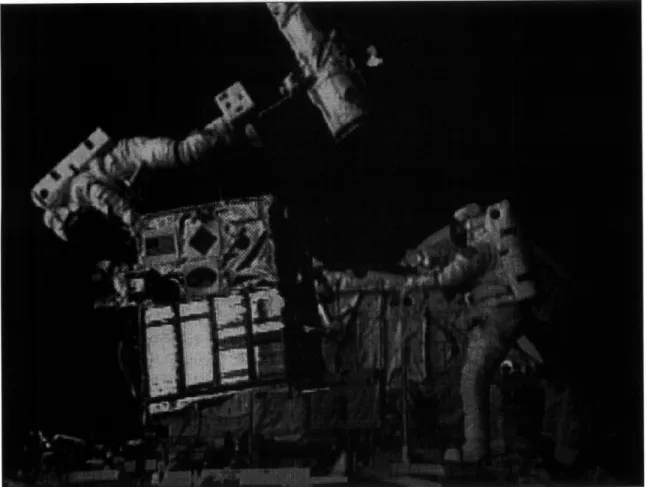
Figure 2.6 Astronaut attempting to attach capture bar to satellite interface ring. ... 46
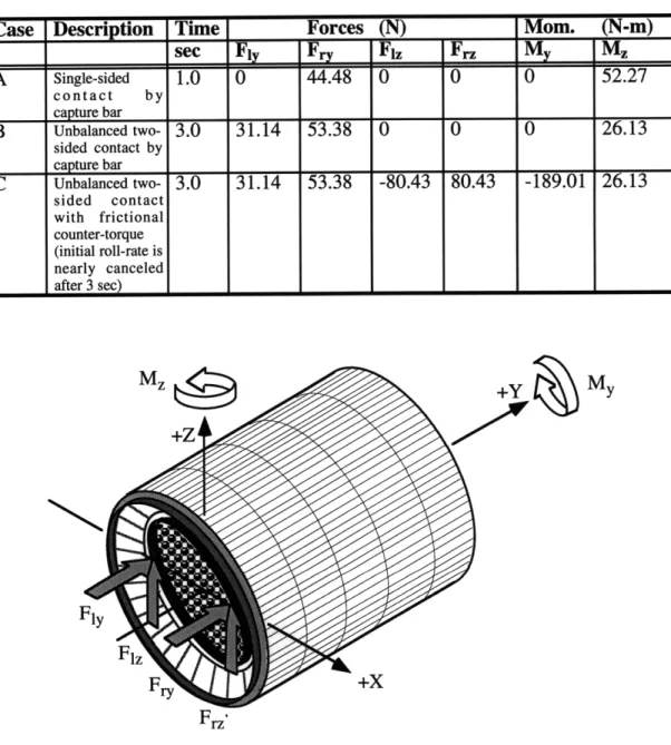
Figure 2.7 Forces and moments produced by the contact points of the capture bar on the satellite ... ... ... 48
Figure 2.8 Geometry for astronaut arm kinematics. ... 50
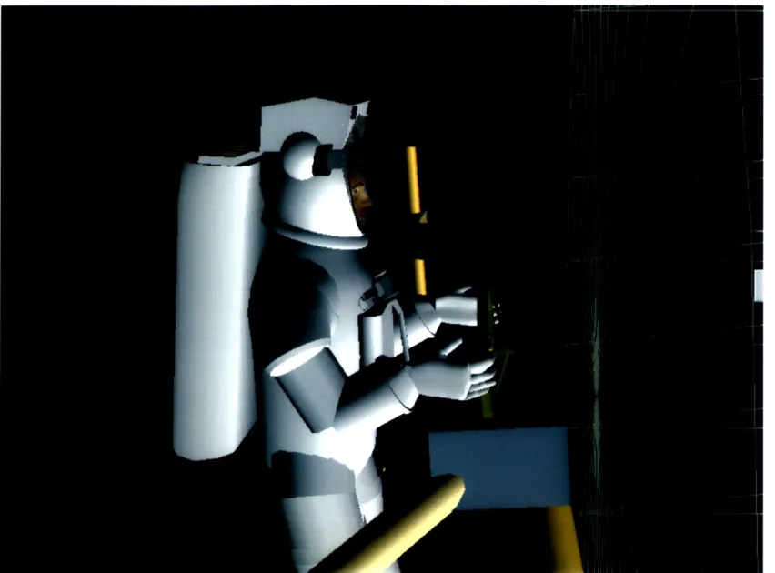
Figure 2.9 Close up view of astronaut and capture bar at start of Intelsat sim ulation ... 53
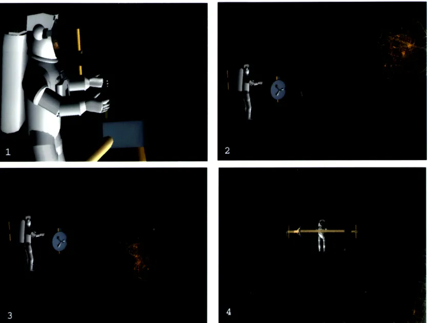
Figure 2.10 Animation sequence of Intelsat simulation for case C (unbalanced two-sided contact with counter-rotary moment) ... 54
Figure 2.11 Translational (top) and rotational (bottom) motion of Intelsat VI satellite following Case C interaction (unbalanced two-sided contact with counter-rotary moment) ... 55
Figure 3.1 Two d.o.f. model of astronaut arm ... 60
Figure 3.2 EVA crewmembers with Spartan 204 free flyer payload. ... 65
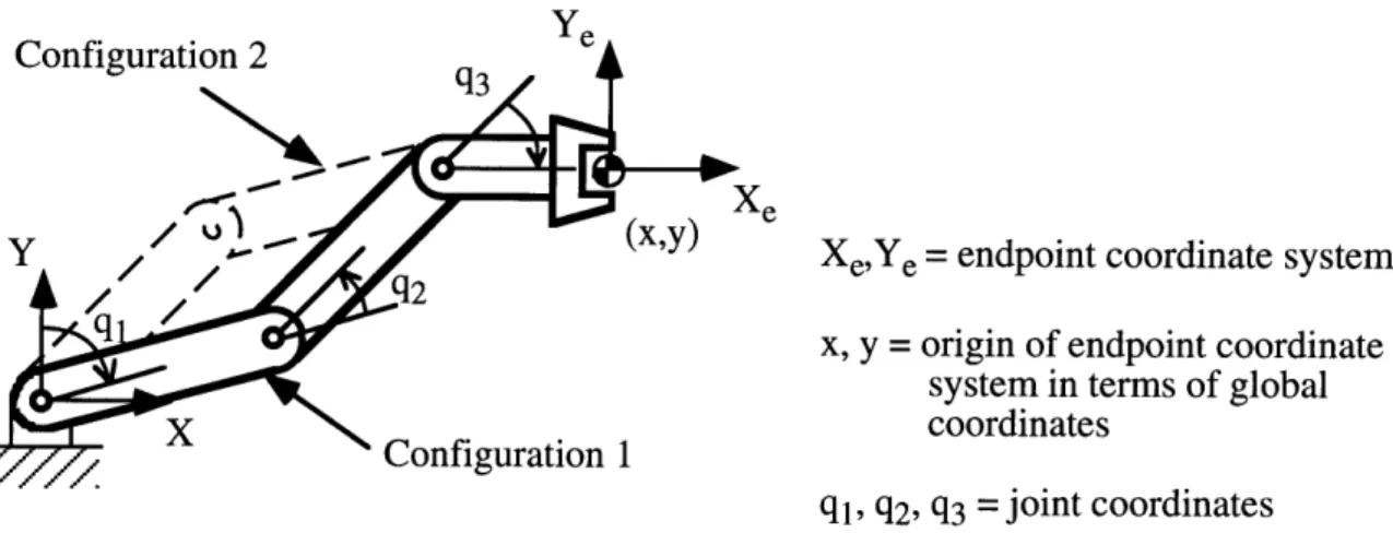
Figure 3.3 Illustration of joint coordinates and endpoint coordinates and occurrence of multiple solutions in systems with redundant degrees of freedom ... .... 68
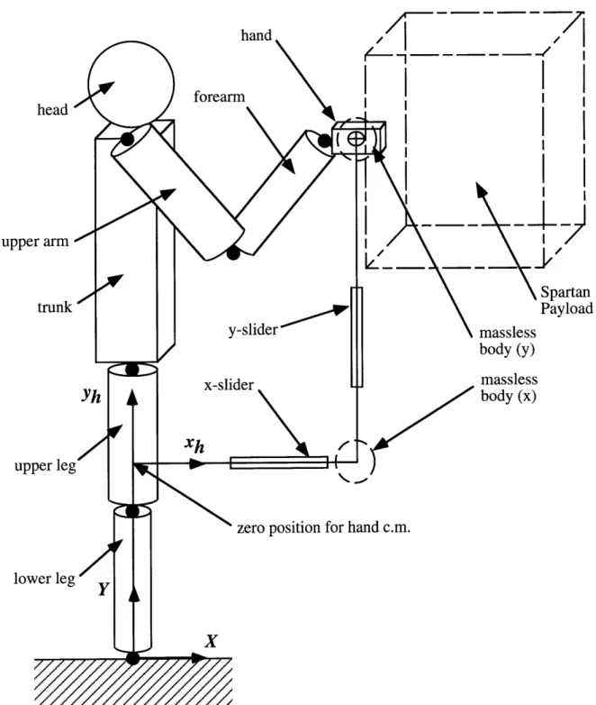
Figure 3.4 Sketch of eight segment system showing massless bodies and sliding joints for prescribing motion of center of mass of hand. ... 72
Figure 3.5 Reference configuration for description of dynamic system. ... 74
Figure 3.6 Initial configuration of system for application of test functions. ... 77
Figure 3.7 Initial configuration for simulation and prescribed circular trajectory of hand... .. 80
Figure 4.1 Animation sequence for simulation no. 1 -fixed lower body. ... 87
Figure 4.2 Joint angle plots for simulation no. 1 (fixed lower body) ... 89
Figure 4.3 Joint velocity plots for simulation no. 1 (fixed lower body) ... 91
Figure 4.4 Joint acceleration plots for simulation no. 1 (fixed lower body) ...93
Figure 4.5 Joint torque plots for simulation no. 1 (fixed lower body) ... 95
Figure 4.6 Animation sequence for simulation no. 2 -compliant lower body. ... 99
Figure 4.7 Joint angle plots for simulation no. 2 (compliant lower body) ... 101
Figure 4.8 Joint velocity plots for simulation no. 2 (compliant lower body)... 103
Figure 4.9 Joint acceleration plots for simulation no. 2 (compliant lower body)... 105
Figure 4.10 Joint torque plots for simulation no. 2 (compliant lower body). ... 107
Figure 4.11. Two images of EVADS screens showing different viewing angles of simulation no. 1 -fixed lower body ... 110
Figure 4.12 Two images of EVADS screens showing different viewing angles of simulation no. 2 -compliant lower body ... 111
Figure 5.1 Lower leg brace device for reducing ankle torques during EVA mass manipulation tasks ... 118
List of Tables
Table 2.1 Basic requirements for a short term life support system. ... 23 Table 2.2 Physical properties of Intelsat VI satellite. (Holloway 1992 ... 47 Table 2.3 Three cases of forces and moments produced by interaction between
the crewmember with the capture bar and the satellite ... 48 Table 3.1 Mass property data for Spartan 204 free flyer... 66 Table 4.1 Comparison of hand calculated and computer simulation torques for
test conditions in shoulder, elbow, and wrist joint. ... 85 Table 4.2 Key for interpreting multi-curve plots ... 86 Table 4.3 EMU joint range of motion limits (edited from NASA-STD-3000) ... 88 Table 4.4 Maximum and minimum angles reached by articulated joints during
simulation No. 1 -Fixed Lower Body ... 90 Table 4.5 Maximum and minimum velocities for articulated joints during
simulation No. 1 -Fixed Lower Body ... 92 Table 4.6 Maximum and minimum accelerations for articulated joints during
simulation No. 1 -Fixed Lower Body ... 94 Table 4.7 Maximum and minimum torques reached by system joints during
simulation No. 1 -Fixed Lower Body ... 96 Table 4.8 Maximum and minimum angles reached by articulated joints during
simulation No. 2 -Compliant Lower Body. ... 102 Table 4.9 Maximum and minimum velocities for joints during simulation No. 2
-Compliant Lower Body... 104 Table 4.10 Maximum and minimum accelerations for joints during simulation
No. 2 -Compliant Lower Body. ... 106 Table 4.11 Maximum and minimum torques for joints during simulation No. 2
List of Acronyms and Abbreviations
c.m . ... CAD ... CAT ... d.o.f. ... EM U ... ESA ... EVA ... EVADS ... g ... ... JSC ... LCVG ... LEO ... M IT ... M M U ... M RI ... NASA ... OOM ... ORU ... PFR ... PLSS ... RM S ... rpm ... SSM ... STS ... TM G ... W ET-F ... center of massComputer Aided Design
Computerized Axial Tomography degree(s) of freedom
Extravehicular Mobility Unit (Shuttle Spacesuit) European Space Agency
Extravehicular Activity EVA Dynamic Simulation
acceleration of free fall on Earth (9.806 m/s2) Johnson Space Center
Liquid Cooling and Ventilation Garment Low Earth Orbit
Massachusetts Institute of Technology Manned Maneuvering Unit
Magnetic Resonance Imaging
National Aeronautics and Space Administration Object Oriented Modeler
Orbital Replacement Unit Portable Foot Restraint Portable Life Support System Remote Manipulator System revolution(s) per minute Solid Surface Modeler Space Transportation System
Thermal and Micrometeoroid protection Garment Weightless Environment Training Facility
1. Introduction
By way of introduction, this first chapter familiarizes the reader with the concept of extravehicular activity performed in spaceflight, the motivation for applying multibody dynamical simulation to extravehicular activity, and the objectives and contribution of the research effort. The chapter concludes with a synopsis of the contents of the thesis.
1.1 Description of Extravehicular Activity
Extravehicular activity (or EVA) is a term commonly used in spaceflight operations to refer to the performance of tasks by an astronaut outside the confines of the space vehicle that serves as his normal habitation volume. Actually, the use of the word "extravehicular" is somewhat of a misnomer since, for most conceivable EVA tasks performed in spaceflight, the astronaut must wear a spacesuit which provides all the necessary life support functions that the home spacecraft provides. Thus, in essence, the astronaut's spacesuit is a miniature spacecraft. Generally, to perform an EVA, an astronaut is provided with an individual life support system and spacesuit that allow him sufficient dexterity and tactility to physically interact with objects in the space environment. Due to the harshness of the space environment, and the multiple functions that the spacesuit must perform, the spacesuit places significant constraints on the astronaut's movements and sensing ability. This, compounded with other factors such as weightlessness, vacuum, thermal loads, and disorientation, makes the performance of tasks during EVA very challenging.
The first EVA was performed by Alexei Leonov of Russia in 1965, followed shortly thereafter by the first American spacewalk, performed by Edward White. The purpose of these early EVAs was simply to prove the feasibility of placing humans in free space (Newman and Barratt 1995). EVA became an operational capability during the Apollo program and for the first time humans were able to walk on another celestial body. During the Russian Salyut and Mir space station programs, and during the U.S. Space Shuttle program, EVA proved its worth as a highly versatile operational capability. EVA should be looked upon as a valuable resource for space station construction and future human space exploration efforts.
Recently, the EVAs performed on Mir and the Space Shuttle Orbiter have become more complex and more challenging. Good examples are satellite capture and repair missions, the Hubble Space Telescope repair mission, and contingency EVAs. During
some of these missions the dynamics of the environment have proven to be counterintuitive during the execution of EVA tasks and in some cases have led to difficulties and even failures. For instance, when an astronaut attempted to capture a
slowly spinning Intelsat VI satellite with a retrieval mechanism during the shuttle mission STS-49, a lack of appreciation of the dynamics of the system, and limitations of the physical simulators used to train for the mission, led to repeated failures of the satellite capture procedure. The astronauts and mission control were forced to find an alternative solution (Holloway 1992). Crewmembers, performing the first three person EVA in history, positioned themselves at three points within the payload bay of the Orbiter and grabbed the base of the satellite with their gloved hands. It was an impressive and inspiring performance, albeit risky and unplanned.
Until now, development and training activities associated with planned EVAs, in both Russian and U.S. space programs have relied almost exclusively on physical simulators. These include neutral buoyancy facilities, air bearing floors, aircraft flying Keplerian trajectories, and suspension systems. Each facility, however, has inherent limitations that prevent true simulation of the EVA environment. In the water tanks it is hydrodynamic drag; on the air bearing floors it is friction and limited degrees of freedom; in parabolic aircraft it is limited duration; and in the suspension systems it is limited degrees of freedom and range of effectiveness. Using a combination of these simulators tends to compensate for their limitations, but still cannot account for every effect of weightlessness.
1.2 Motivation
To complement and make up for the shortcomings of physical simulators, an effort to develop a computational simulation system to model human dynamic motion has been initiated. Although the system's utility extends to a broad range of human motion tasks and robotics, including earth-based studies, it is being developed with the prime objective of producing a valuable analysis tool for evaluating the performance of human motion in weightlessness during extravehicular activity. This research effort takes advantage of experience gained in the field of computational simulation of multibody dynamics.
Various techniques have been developed to obtain the dynamics equations of a multibody system. The most well known methods include the classic Newton-Euler approach, the Lagrangian formulation, and Kane's method. There are two principal approaches to the formulation of the dynamic system equations: symbolic (or algebraic) and numerical. The symbolic approach uses one of the three methods given above to derive the dynamic equations, either by hand (which becomes impractical for systems of
more than three bodies) or using a computer program. Two examples of such programs are AUTOLEVI (Schaechter and Levinson 1988) and SD/FAST2 (Hollars, Rosenthal et al. 1994), both of which are based upon Kane's method (Kane and Levinson 1985). There are also programs available for generating the equations using numerical approaches. Some examples include DADS (Haug 1989) and ADAMS (Chace 1978). In addition, commercial software developed recently has introduced powerful means of analyzing quasi-static motions of human musculoskeletal systems, for example SIMM3.
It is a relatively new idea to apply computational techniques to simulation of EVA tasks. Some existing programs have focused on EVA simulation as their prime objective, but most of these programs are aimed at either computer graphics and CAD (Price, Fruhwirth et al. 1994) or anthropometric applications (McDonnell-Douglas 1994). Few, if any, of these programs go into any significant detail on the simulation of multibody dynamics.
An important advantage of multibody dynamic simulation is the ability to account for effects that are absent in physical simulators or masked by their limitations. In addition, this type of simulation can be performed relatively economically and quickly. It represents a particularly attractive capability when used as a complement to the existing simulators.
Some disadvantages of computational simulation are the rapid rise in complexity as the number of bodies and degrees of freedom in the system increase, and the occurrence of multiple solutions to inverse kinematic and inverse dynamic analyses in systems with redundant degrees of freedom (Asada and Slotine 1986). These difficulties can be minimized by keeping the model as simple as possible, and by using constraints or optimization to select a particular solution. Another issue to be considered is the accuracy with which physiological systems of the human are modeled. Mass properties of human body segments and joint kinematics are usually highly simplified in these types of analyses and it is wise to compare the data obtained from simulation with experimental results.
It is clear that a need exists for a method of EVA simulation that avoids the shortcomings of physical simulators and which is at the same time economical and convenient to use. Describing how this need can be addressed is the subject of this thesis.
1OnLine Dynamics, Inc., Sunnyvale, CA 2Symbolic Dynamics, Inc., Mountain View, CA.
3
1.3 Objectives and Contribution
The primary objective of the research described in this thesis is to demonstrate the significant value of multibody dynamics analysis for the simulation of EVA tasks. In particular, it is believed that computational dynamic simulation has certain advantages over physical simulators and complements them very well. The main advantage is the ability to represent all the degrees of freedom available to a body in weightlessness (six degrees of freedom for a single isolated body - three translational and three rotational) and at the same time avoid some of the detrimental effects that physical simulators are subject to, such as friction in air bearing floors or viscous drag in neutral buoyancy facilities. Other advantages include low cost, flexibility, quick turnaround, low manpower requirements, and ease of operation.
Of course there is a price to pay for all these advantages. Simulation of multibody dynamics is inherently computationally intensive. In addition, greater accuracy and realism is gained through adding degrees of freedom and geometric detail to the dynamic system model, further increasing the complexity of the simulation, the computer processing time, and the work required of the analyst. In practice, the analyst must consider a tradeoff between the complexity of the dynamic system model and the accuracy and validity of the results in regards to the particular situation being simulated.
Certain specific objectives were established to guide the research effort. These 8 prioritized objectives are:
1) Develop a convenient means of modeling the dynamic system and tailor it to the particular needs of EVA simulation.
2) Transform the description of the dynamic system into equations of motion represented in computational form.
3) Develop computer code to drive simulations of the dynamic system under a variety of conditions.
4) Explore methods of prescribing the motions to be performed in a task-oriented form, the way that an astronaut or trainer might think of the operation, without the need to explicitly specify the kinematics (positions, velocities, and accelerations) of each segment. In other words, perform an inverse kinematics analysis, given only the motion of the endpoint of the system.
5) Determine the joint torques required to drive the system in performing a particular motion by using the calculated segment kinematics in an inverse dynamics analysis.
6) Create a graphical animation and data display user interface.
7) Show how the results of the inverse kinematics and inverse dynamics analyses are interpreted.
8) Demonstrate the means by which simulations are improved in an evolutionary manner.
To achieve these objectives a seven segment model of an astronaut is created with an eighth segment attached to the hand representing a large mass to be manipulated during an EVA task. The equations of motion are derived using SD/FAST, based on Kane's method, which creates code to represent the equations of motion in computational form. Additional code is created to drive the system during two simulations, the second simulation being an improvement on the first. Finally, the results are visualized through the aid of an animation and data plotting program, which has been named EVADS (EVA Dynamic Simulation). All of these operations are performed on a Silicon Graphics Indigo2 computer.
1.4 Synopsis of Thesis
In addition to the introduction chapter presented here, this thesis is comprised of chapters dealing with background information, methodology, results, and discussion and conclusions. The Background chapter provides a brief history of EVA; a description of the space environment encountered in EVA (mostly in low Earth orbit); a summary of spacesuit requirements and the effects of the spacesuit's construction on human body dynamics; a discussion of training methods and physical simulators used in preparation for EVA; an introduction to computational simulation of multibody dynamics; and an example of dynamical simulation as applied to the modeling of the Intelsat VI satellite capture EVA.
The Methodology chapter first works through an example of dynamical equation formulation applied to a simple two degree of freedom system; then describes the Space Shuttle mission STS-63 Spartan mass handling EVA which serves as the subject for the
two main simulations presented in the thesis; and finally presents the details of how the dynamic simulations are performed, including the creation of the system's description file, formulation of the equations of motion, inverse kinematics, inverse dynamics, and animation and data plots using EVADS. In both simulations, the EVA task is to manipulate the Spartan payload around a circular trajectory. In the first simulation, the radius of the circle is 0. 15m and the trajectory is completed in 10 seconds. In the second simulation, the radius of the circle is 0.075m and the trajectory is completed in 20 seconds. In addition, the lower body joints (ankle, knee, and hip) are fixed in the first simulation, but are allowed some compliance (by means of passive springs and dampers) in the second simulation.
The Results chapter first presents data obtained from joint torque test functions, followed by data obtained from the two EVA simulations. It is observed that, in the first simulation, the wrist joint exceeds the range of motion limits and is required to exert torques beyond the level of human capability. The second simulation solves these problems by starting with the arm in a more comfortable position and by requiring the hand to follow a smaller circular trajectory at a lower speed (thus requiring less torque). The chapter concludes by presenting results of the animation and data plotting functions of EVADS.
In the Discussion and Conclusion chapter, the research objectives are recapped and the extent to which they were achieved is indicated. The results of the two simulations are deliberated with particular attention given to the success of implementing compliance in the lower body joints. The effectiveness of the animation and data representation abilities of EVADS is assessed. Some general conclusions about the research are drawn, especially relating to the feasibility of using computational multibody dynamics to simulate EVA tasks. Finally, the chapter concludes with suggestions for further research and a short summary of the thesis.
2. Background
This chapter presents background information on EVA and multi-body dynamic simulation to familiarize the reader with the unique challenges of performing EVA, the manner in which astronauts prepare for spacewalks, and how multibody dynamic simulation can improve this preparation. It begins with a brief synopsis of the EVA experience in both the U.S. and Russian space programs. Owing to the relative brevity of U.S. Space Shuttle flights and the long hiatus due to the Challenger accident, American astronauts are far behind their Russian counterparts in the total number of EVA hours accumulated.
The relative inexperience of American astronauts in performing spacewalks has become an issue in regards to the rigorous EVA assembly schedule planned for the International space station. According to the latest estimates, astronauts and cosmonauts will spend about 888 EVA hours assembling the station. An additional 171 hours per year are expected for maintenance requirements (Harwood 1995). Concern has been raised as to whether NASA will be able to support such a vigorous schedule of spacewalks. NASA has recently expressed confidence that EVA has become a routine operation and that the demands of the space station assembly task can be met. To make sure that EVA crews are not overworked, limits have been designed into the EVA timelining protocol. In general, this ensures that crewmembers will have at least one rest day between consecutive EVAs and will not be called upon to perform an EVA before the fourth day of flight after they have overcome any symptoms of space motion sickness. Nevertheless, it is clear that it will be more important than ever to ensure that astronauts are well prepared to perform these spacewalks and have a good understanding of the environment they will encounter. A major part of this preparation should include both training and analysis - qualitative and quantitative - of the dynamics of object manipulation, tool operation, body translation, and body orientation. All complex tasks should be carefully analyzed. Even tasks that might be perceived as relatively simple could have unexpected results when performed in the deceptive environment of low Earth orbit, a lesson that has been hard learned in past EVAs.
After the following section on EVA history, a brief description of the space environment is presented. Environmental factors determine the life support functions that a space suit must provide, but the physical realities of spacesuit construction have a significant effect on an astronaut's mobility and senses.
Until recently, EVA research and training has been conducted almost exclusively by means of physical simulators. Different types of physical simulators and their strengths and weaknesses are described later in this chapter followed by a discussion of computational simulation methods and dynamic equation formulation in multi-body systems. In particular, various ways in which computational simulation can be applied to EVA are identified.
The chapter concludes by describing a simple demonstration of dynamic simulation applied to an actual EVA. The goal of the spacewalk was to capture a stranded Intelsat satellite and attach it to a new upper stage kick motor. Unfortunately, a lack of understanding of the dynamic environment, compounded by the limitations of physical simulators, led to failure of the rehearsed procedure. The main reasons for this failure are demonstrated by the simulation results.
2.1 A Brief History of EVA
A good overview of the history of extravehicular activity is provided by Newman and Barratt in Chapter 22 of Space Life Sciences (Newman and Barratt 1995). The first EVA was performed by Russian cosmonaut Alexei Leonov in March 1965. The EVA lasted for ten minutes, during which Leonov floated free of his Voskhod capsule while attached to a 5 m umbilical which supplied air and communications. Edward White became the first American astronaut to perform an EVA in June 1965 during a Gemini-Titan 4 flight. These EVAs were primarily to demonstrate that a human could operate in free space while protected by a space suit which provided a pressurized gas environment for respiration, air cooling, and prevention of edema and blood boiling. Since the early spacesuits had restricted mobility and lacked active body cooling, the spacewalkers quickly became fatigued while performing even simple tasks. Other difficulties underscored the need for restraint mechanisms such as foot restraints, handholds, and tethers.
EVA became an operational capability during the Apollo program. From the time Neil Armstrong and Edwin "Buzz" Aldrin set foot on the moon, Apollo astronauts accumulated a total of 160 hours of extravehicular activity time on the lunar surface. They traveled 100 kilometers on foot and with the lunar rover, and collected 2,196 rock and soil samples during these highly successful EVAs.
The Apollo spacesuit design exhibited significant improvements over the spacesuits used in the Mercury and Gemini programs. A major modification was the replacement of the life support umbilical with an autonomous backpack life support system which supplied breathing oxygen, pressurization, and body temperature regulation through a
liquid cooling garment. In addition, the suits had much greater mobility than previous generation suits, especially in the legs, allowing for better locomotion.
The value of EVA was dramatically demonstrated during the Skylab program. A portion of the space station's outer skin and one of the solar panels were lost during launch, resulting in an overheated and underpowered station. The mission was salvaged when astronauts Joseph Kerwin and Charles "Pete" Conrad erected solar shades and freed the second solar panel by means of EVA. The temperature of the station was reduced to the nominal range and sufficient power was then available to run the station's systems.
The Russians had meanwhile reduced their usage of EVA, due to difficulties in their early attempts. They resumed EVA during the Salyut 6 program (1977-1981) to replace equipment and retrieve experiment samples from outside the space station. Cosmonaut Georgi Grechko performed an important EVA to determine whether the cone of the Salyut 6 docking port had been damaged. During the Salyut 7 program, experience was gained in construction, telemetry and material science. EVAs were also performed to study cosmic radiation. A significant milestone occurred on July 25, 1984, when cosmonaut Svetlana Savitskaya became the first woman to perform an EVA. She used a portable electron beam device to cut, weld, and solder metal plates.
NASA increased it's EVA experience during the Space Shuttle missions. Spacewalks were divided into two categories: planned and contingency EVAs. Planned EVAs focused on specific mission objectives. Contingency EVAs allowed astronauts to respond to unexpected problems during the actual mission. The thirteen two-person EVAs performed between 1983 and 1985 from the Space Shuttle Orbiter met the goals of: demonstrating and evaluating the Extravehicular Mobility Unit (EMU), a 29.6 (4.3 psi) spacesuit; testing the Manned Maneuvering Unit (MMU); working with the Remote Manipulator System (RMS); assembling space structures; and repairing equipment and satellites. After a five year lapse, largely due to the Challenger accident, EVAs were resumed in the Shuttle program in April, 1991. Since then, the diversity of operations performed during spacewalks has significantly increased. The most recent EVAs have focused on preparations for assembly of the international space station, such as crew translation aids, mass handling, and assembly techniques.
The most recent Russian EVAs have occurred during the Mir space station program. In April 1987, Yuri Romanenko and Alexander Laveikin performed a contingency EVA to remove an obstruction causing a docking problem between the Mir and Kvant modules. In February 1990, the first test of the Russian SPK unit (similar to the American MMU) was performed. In July 1990, cosmonauts Alexander Balandin and Anatoly Solovyov performed an exciting EVA in which they extended a ladder from the Kvant 2
module to the Soyuz capsule to repair some heat insulation blankets. Thanks to their continuous presence in orbit with the Mir space station, in contrast to the short trips into space on the Shuttle in the American space program, the Russians were able to
accumulate many more hours of EVA experience than the Americans.
Even though NASA has gained experience in a wide variety of EVA tasks, the actual number of hours of EVA time accumulated is still relatively small. In fact, the number of EVA hours logged to date by US astronauts is only about one quarter of the number of hours estimated for the construction of the space station. In addition, there is still much room for spacesuit improvements, especially in terms of mobility, comfort, operating pressure, and longevity. Of greatest significance to the research effort described in this thesis, is the fact that the complexity of multibody dynamics in space continues to be a significant difficulty for EVA astronauts, as was evident in the STS-49 EVA which is described in a later section. Other than empirical anthropometric studies, little has been done in the way of quantitative analysis and simulation of EVA. The purpose of this thesis is to demonstrate the great value of research efforts in this area.
Before discussing multibody dynamics in more detail, it is worth taking a brief look at the space environment that the EVA crewmember encounters. The realities of this environment dictate that an astronaut must wear a spacesuit when he leaves the confines of his spacecraft. The physical properties of a spacesuit, however, have a significant impact on the astronaut's mobility. Properties of the space environment and spacesuits are described in the next two sections.
2.2
The Space Environment and EVA
The majority of EVAs performed to date, with the exception of the Apollo missions which left Earth orbit, have taken place in the space environment of low Earth orbit (LEO). The LEO environment is characterized by hard vacuum, weightlessness, various forms of radiation, and micrometeorites and orbital debris. A good description of the space environment is provided by Griffin and French in the text Space Vehicle Design (Griffin and French 1991).
In a typical low Earth orbit, say at 200 km, the 1976 US Standard atmosphere lists a temperature of 855 'K (582 C), a pressure of 8.47x10- 5 N/m2 (1.22x10⁻⁸ psi) and a density of 2.54x10⁻¹⁰ kg/m3 (1.59x10⁻¹¹ lb/ft3). The very high temperature can be attributed to direct solar radiation when unprotected by the atmosphere's shielding. The low pressure and density are evidence of the hard (but not complete) vacuum, even in a relatively low orbit. Outgassing occurs in most materials exposed to this vacuum.
Furthermore, ionized atomic oxygen present at this altitude is highly reactive and may degrade materials.
Weightlessness has a major impact on extravehicular activity. A weightless condition is experienced in orbit because centripetal acceleration gives rise to a centrifugal force which counterbalances the gravitational attraction of the Earth. Small accelerations in the range of 10-3 to 10-11 -g (a "g" is one standard unit of Earth's gravitational acceleration, a value of 9.806 m/s2) are nevertheless encountered due to various perturbations (i.e., space gas drag, thruster firings, crew disturbances, etc.). For instance, during the early EVAs performed in the Gemini program it was discovered that an unexpectedly high level of effort was required to perform even simple tasks. During Gemini 9, astronaut Gene Cernan was unable to test a maneuvering backpack (for controlling body translation and orientation) due to exhaustion experienced in putting on the unit (Griffin and French 1991). Other difficulties were encountered by astronauts in simply handling life support tethers and shutting the spacecraft hatch following an EVA. These difficulties were attributed in part to the bulkiness of the spacesuit, but more significantly to the lack of surfaces and masses to provide the reaction forces normally supplied by the combination of friction and gravity on the Earth's surface. A study conducted by Wortz during the Apollo era attempted to determine why human performance capability was sometimes diminished during spacewalks, leading to increased energy expenditure (Wortz and Prescott 1966). Wortz concluded that the lower efficiency and increased metabolic cost of work observed during some activities was due to a combination of the muscular work required to provide necessary reactive forces to compensate for the lack of traction and the physical constraints of the spacesuit. More recently, careful placement of handholds and foot restraints has enabled astronauts to improve their efficiency and perform a wide variety of tasks without exhausting themselves. It should be pointed out that in spite of these difficulties, humans are able to accomplish tasks in weightlessness that could never be accomplished on Earth, such as manipulating very large masses.
Another serious concern for astronauts performing spacewalks is the radiation environment. Almost all of the electromagnetic radiation in the solar system is emitted by the Sun. Near the Earth, the energy density is about 1390 W/m2. Thermal radiation produces wide fluctuations in temperature in bodies in low Earth orbit. Very high temperatures, in the range of 800 to 900K, are experienced by surfaces exposed to direct solar radiation, whereas surfaces that are in shadow, and exposed only to open space, can experience extremely low temperatures (less than 100K). Ionizing radiation consists of high-energy particles (protons and electrons) and photons. Galactic Cosmic Rays are an additional source of radiation consisting of high energy photons, alpha-particles, and
heavy nuclei. Fortunately, for EVAs occurring in low Earth orbit, much of this radiation is shielded by the Van Allen belts in the geomagnetic field.
Micrometeoroid flux near Earth is calculated on a log scale versus particle mass with few particles exceeding 10-6 g. For most purposes, a density of 0.5 g/cm3 and a velocity of 20 km/s can be used as average values. Most micrometeoroids are extremely small. The rule of thumb is that a 1 gg particle will just penetrate a 0.5 mm thick sheet of aluminum. Space debris flux levels exceed those of micrometeoroids and thus pose a greater threat. It is estimated that there are 5408 objects larger than 10 cm, approximately 40,000 objects larger than 1 cm, and literally billions of particles in the 0.01 to 0.5 mm range in Earth orbit. This fact must be considered when designing spacesuit outer shells to resist puncture by means of particle impact. Of course a tradeoff between particle size and impact probability must be exercised
2.3 Spacesuit Requirements and Implications
It is clear from the description in the previous section that the space environment is not a friendly one for humans. To be able to venture beyond the confines of their spacecraft, astronauts must don spacesuits with associated life support systems (which may be portable or connected via an umbilical). The spacesuit and life support system
must provide the human with the necessary requirements for sustaining life and at the same time protect them from the hazards of the environment.
The spacesuit itself must provide three basic requirements: a pressure vessel around the astronaut; protection from environmental hazards; and mobility for performing motion tasks and doing work. The life support system, or portable life support system (PLSS), must supply the following: pressure control and oxygen supply; removal of carbon dioxide and trace contaminants; thermal control; humidity control; and power, communications, and data display. A PLSS has slightly different requirements than a vehicle life support system: it is generally expected to operate for a shorter duration; it does not necessarily need to supply food or water; and it is more closely coupled with the human's metabolic rate (Webbon 1994).
The most basic requirements for a short term life support system (not including water and food) are given in Table 2.1. The two primary categories are air and temperature.
Table 2.1 Basic requirements for a short term life support system.
Air
Total Pressure 160-170 mmHgA (3.09-14.70 psi) Oxygen Partial Pressure 160-260 mmHgA (3.09-5.03 psi) Nitrogen Partial Pressure 0-600 mmHgA (0-11.60 psi)
Carbon Dioxide Partial Pressure:
- continuous exposure < 1.5 mmHgA (.03 psi)
- short-term exposure < 20.0 mmHgA (.39 psi) Humidity Range 40-70% relative humidity Temperature
Desired Range 60-80 deg F
Metabolic Heat Production 100-1,000 Watts
In addition to the life support requirements, the spacesuit must also protect crewmembers from environmental hazards such as micrometeorites, space debris, radiation, and even sharp objects on other spacecraft and equipment (particularly due to the risk of puncture and pressure loss). In order to meet these many requirements, spacesuit designers have usually opted for a soft suit with many layers of different materials which perform various functions. In fact, the Apollo space suit had 21 layers according to the Du Pont company (Kozloski 1994). The Extravehicular Mobility Unit (EMU) used in the Space Shuttle program is also a fabric suit made up of many layers. The liquid cooling and ventilation garment (LCVG) of the EMU is made from nylon and spandex with a tricot lining. Cooling tubes made from Ethylene-vinyl-acetate are woven through the spandex. Next comes the pressure garment, which is made of urethane coated nylon covered by a woven dacron restraint layer. The outermost layers make up the thermal and micrometeoroid protection garment (TMG). The liner of the TMG is neoprene-coated ripstop nylon, followed by five layers of aluminized mylar thermal insulation, and finally a woven blend of kevlar and nomex synthetic fibers coated with teflon makes up the familiar white outer layer (Newman and Barratt 1995).
It is a great tribute to the spacesuit designers that a human is able to move at all when encumbered by this many layers. The most significant impact on astronaut mobility and workload in a fabric suit is increased pressure caused by a reduction in the volume of the
suit when a joint is flexed. To minimize this effect in fabric suits, designers have incorporated axial restraint lines which hold the centerline of a joint at a near-constant
length. The volume decreases on the inside of the joint which is compensated for by expanding folds on the outside. Experimental hard suit designs like the NASA Ames
AX-5 have almost entirely eradicated this effect by maintaining a constant volume during movements. The fact remains, however, that spacesuits still impose significant constraints on human movement. In addition to limiting joint range of motion, the mechanical properties of suits (i.e., elasticity, friction, and damping) and the mass properties of the associated suit segments impact EVA dynamics and can not be ignored. It is highly desirable to be able to simulate these various effects and predict their impact on specific EVA tasks. In addition, while a PLSS avoids the hindrance of umbilical lines, it must be realized that this massive backpack significantly displaces the center of mass of the combined astronaut and EMU. This can have surprising results in body translation or rotation, especially for partial gravity locomotion, and represents another important
factor to be considered in dynamic simulation.
2.4 Training and Physical Simulators
Due to problems encountered in early EVAs, mission planners and training personnel began looking for ways in which they could better prepare astronauts for the unfamiliar environment encountered in EVA. One way of addressing the problem was to construct physical simulators. The main goal of these simulators was to try to give astronauts a feel for the way objects responded in weightlessness or in partial gravity. Some simulators sought to provide the additional degrees of freedom available to a body in space, while others aimed at imitating hypogravity conditions for locomotion studies (particularly in preparation for the Apollo moonwalks). During the past three decades a great variety of facilities have been built, many of them still in use today. They include neutral buoyancy tanks, air bearing floors, aircraft flying Keplerian trajectories, and various types of suspension mechanisms. Free fall towers and sleds were also used, although not often for human studies and even more seldom, if ever, for EVA studies. A review of the various techniques was recently published (Davis and Cavanagh 1993). A short description of the most important facilities used for simulating EVA, along with their advantages and disadvantages, is presented below.
2.4.1 Neutral Buoyancy Tanks
One of the early proponents of neutral buoyancy facilities was Werner Von Braun. At his behest, a large water tank was constructed at NASA's Marshall Space Flight Center. A picture of astronauts training for an EVA in this facility is shown in Figure 2.1. Since
Facility (WET-F) at Johnson Space Center, a small tank at NASA Ames Research Center, and private facilities at McDonnel Douglas in Huntington Beach, CA and the University of Maryland. Weightlessness or partial gravity is simulated by adjusting ballast weights and air containers until gravity is canceled to the desired extent by the buoyancy force of the water. Neutral buoyancy is better suited to studies of slow motion tasks such as range of motion studies (Reinhardt 1989), but has also been used
successfully for locomotion studies (Newman and Alexander 1991).
Advantages of this technique include the large working volume, an almost unlimited test duration, and the ability to approximate the full six degrees of freedom. A major disadvantage is the presence of hydrostatic drag and water displacement inertia. Astronauts have often expressed surprise at how much more easily objects move in the vacuum of space when unencumbered by the retarding forces present in the water tank. In fact some astronauts have even observed that their neuromuscular system sometimes appears to "learn" motion patterns during simulations in the neutral buoyancy facility that subsequently become a hindrance in the actual EVA performed in space. Furthermore, as every scuba diver knows, buoyancy usually varies with depth due to the difference in density between water, air, and other materials, making it difficult to maintain neutral buoyancy during depth changes.
Figure 2.1 Astronauts during EVA training in the Neutral Buoyancy Facility at Marshall Space Flight Center. (Source: NASA)
2.4.2 Air Bearing Floors
Air bearing floors have proven useful mainly for translation tasks. The floor itself must be very flat to obtain the desired low friction. Usually stainless steel is used for this purpose. Each separate object to be simulated, be it a satellite or an astronaut, is supported by three or more flat pads in order to distribute the weight in a stable way. Air is expelled through the bottom of these pads and enough pressure is generated to support the entire object so that it can coast over the floor with very little friction. These air pressure pads are referred to as "air bearings". This technique of simulation has proven particularly useful for translation and rotation motions with devices such as the manned maneuvering unit (MMU). A picture of a spacesuited astronaut conducting a simulation on an air bearing floor is shown in Figure 2.2.
The main advantage of this facility is that friction and damping forces are very low. In addition, the simulation time is relatively unlimited and it is easier to set up test sessions on the air bearing floor than in facilities such as neutral buoyancy tanks and parabolic aircraft. An important disadvantage of the simulator is the limitation on the number of degrees of freedom. The air bearing floor itself, being a plane, can only accommodate three degrees of freedom, two in translation and one in rotation. Other degrees of freedom might be accommodated by a combination of mechanical bearings and/or suspension systems although increasing the mechanical complexity often introduces other problems such as static friction or inertia. Furthermore, the low friction level can be misleading. Friction in the air bearing operation, and drag from the surrounding air sometimes mask small forces and torques in the dynamic system which can turn out to be of critical importance in the frictionless vacuum of space. This effect was a significant factor in the difficulties encountered in the Intelsat VI capture EVA discussed later in this chapter.
2.4.3 Aircraft Flying Parabolic Trajectories
NASA, ESA, the Russian Space Agency, and even some private companies such as Weaver Aerospace, operate aircraft which are capable of flying parabolic (or Keplerian) trajectories to achieve weightlessness through free fall. NASA's KC-135 aircraft (shown in Figure 2.3) was originally commissioned to enable new astronauts to gain experience in weightlessness prior to spaceflight. Since then, the KC-135 and other aircraft have been used for many scientific experiments. Occasionally these aircraft are also used for training in EVA tasks such as getting in and out of a foot restraint for instance.
The parabolic aircraft technique is popular because it offers a very realistic simulation of weightlessness. People and objects can readily achieve six degrees of freedom by floating freely within the cabin. It is also possible to simulate hypogravity or hypergravity by altering the aircraft trajectory as appropriate. Intravehicular tasks or experiments in which weightlessness plays a significant role are usually simulated using this method. The greatest disadvantage of parabolic aircraft is the limited duration of uninterrupted weightlessness. Only 25 seconds of "zero-g" are sustained on average per parabola. To make up for this, the pilots perform repeated parabolas. Unfortunately, the alternating g-level tends to provoke motion sickness in most passengers, hence the "vomit comet" nickname for the KC-135. Motion sickness is particularly dangerous for a spacesuited astronaut due to the risk of emetic clogging air lines or choking the astronaut. Another significant constraint is the limited volume (ranging from about 20 m3 to about 100 m3)
and low vertical clearance (usually not more than 2.5 m) available in these aircraft. This is a serious limitation since many EVAs involve the manipulation of large objects. For these reasons, EVA simulations are most often performed in neutral buoyancy facilities while IVA (intravehicular activity) simulations are most often performed on parabolic aircraft.
2.4.4 Suspension Mechanisms
Suspension mechanisms were quite popular during the early days of the Apollo program. Researchers used cables, pulleys and springs to investigate such topics as the energy costs of locomotion in reduced gravity (Wortz and Prescott 1966), or the mechanical aspects of vertical jumping in different gravity levels (Cavagna, Zamboni et al. 1972). Following Apollo the use of suspension systems diminished, but recently renewed interest in manned planetary exploration has prompted new studies (He, Kram et al. 1991). Most recently, the POGO pneumatic suspension system at Johnson Space Center (shown in Figure 2.4) was refurbished for EVA simulations including object manipulation for the Hubble Space Telescope repair mission.
Suspension mechanisms are useful because they allow a degree of freedom in the vertical direction, something which is hard to achieve using air bearing floors for instance. Also, reduced gravity levels can be simulated. By combining the suspension system with other mechanisms, such as tracks or gimbals, it is possible to approximate all six degrees of freedom. The major disadvantage of suspension systems is their limited range of effectiveness. It is particularly difficult to construct a suspension mechanism which can translate smoothly during forward motion. Also, many suspension systems make use of long springs which have an inherent limitation, the suspension force varies linearly with displacement. Although these limitations are averted in pneumatic suspension systems, like the POGO, they suffer from other detriments such as friction and pressure regulation.
A!R-EARING -- / SUPPORT RAIL PISTON ROD ASSEMBLY -VERTICAL SERVO ASSEMBLY NDER ASSEMBLY LOAD CELL
GIMBAL SUPPORTn mechanism at NASA's Johnson Space Center. (Source: NASA)
2.4.5
Synopsis of Physical Simulators
All the physical simulators used to date have significant limitations in their ability to imitate weightlessness. While these simulators are very useful for research and training in certain types of EVA operations, they are constrained by physical realities. The use of a combination of simulators tends to compensate for the particular shortcomings of each, but it is still not possible to exactly duplicate the effects of weightlessness and vacuum, as experienced in orbit. Occasionally, physical simulators may fail to predict a certain effect or, through misrepresentation of the space environment, introduce habits which are detrimental during the performance of the actual EVA. An additional factor not mentioned above is that many of these simulators are expensive to operate. This is particularly true of the neutral buoyancy tanks and the parabolic aircraft.
As mentioned earlier, it is expected that hundreds of hours of EVA time will be required to assemble the International Space Station. Even if the current facilities were able to perfectly simulate weightlessness, they would not be able to accommodate the tremendous number of hours of training time required and, furthermore, tremendous costs would be incurred. Not only space station EVAs are of interest, planning for other types of EVAs, such as Hubble telescope servicing missions and possibly Lunar and Mars operations, must continue.
Clearly, to meet this growing need, it is desirable to find other ways of simulating EVA operations, particularly if these methods prove economical in terms of both finances and time. The primary goal of the research effort described in this thesis is to demonstrate how computational dynamic simulation can avoid the limitations of physical simulators conveniently and economically and at the same time yield numerical results hitherto unobtainable.
2.5
Computational Simulation of Multibody Dynamics
The discipline of multibody dynamic simulation has progressed to the point where it is now practical to simulate relatively complex dynamic systems fairly accurately, offering an additional way to simulate extravehicular activity with the advantage of avoiding many of the deficiencies of physical simulators. This method also has other attractive features such as low cost, short turnaround time, low manpower requirements, and ease of operation. Although this approach has its own limitations, such as mathematical complexity and model accuracy, its value lies in the fact that it can potentially make up for many of the gaps in the combined capability of physical simulators. For instance, a computational simulation would be capable of achieving the full six degrees of freedom that many physical simulators lack, and at the same time
avoid such detrimental effects as friction (air bearing floor) or viscosity (neutral buoyancy). While it is possible to simulate all objects comprising the dynamic system associated with an EVA, particular emphasis has been given to the goal of modeling the dynamics of the EVA crewmember's body as a system in itself.
At this point it is helpful to introduce some terminology used to describe the topology of multibody systems and this is done with the aid of Figure 2.5. An open Chain structure (Figure 2.5 (a)) is defined as a system of rigid bodies linked together in series. There are no loops. Only one of the bodies may be attached to ground since if two bodies were linked to ground it would constitute a loop structure. A loop structure (Figure 2.5 (b)), or closed chain, contains bodies that are linked together so that if one proceeds sequentially from one body to the next, one will end up back at the first body. Closed chains are difficult to model mathematically due to the additional constraints imposed and many multibody computer programs are incapable of analyzing them. A tree structure is usually defined by a base segment (or body) to which is attached two or more open or closed chains. A human-like example is shown in Figure 2.5 (c) and consists of a base segment (the trunk) to which are attached five open chain structures (the head, two arms, and two legs). The joints used to link the bodies in these structure may have degrees of freedom ranging from one to six (three translational and three rotational).
(a) Open Chain Structure (b) Closed Chain or (c) Tree Structure Loop Structure
0 00
0 0
0 0
Figure 2.5 Topological terms applied to multibody dynamic systems.
The great scope of topics encompassed within the science of human movement is discussed in a CRC Critical Review in Biomechanical Engineering (Hemami 1985). Although slanted toward neuromuscular physiology rather than multibody dynamics, the