Publisher’s version / Version de l'éditeur:
Journal of Thermal Spray Technology, 27, 6, pp. 1011-1024, 2018-07-31
READ THESE TERMS AND CONDITIONS CAREFULLY BEFORE USING THIS WEBSITE. https://nrc-publications.canada.ca/eng/copyright
Vous avez des questions? Nous pouvons vous aider. Pour communiquer directement avec un auteur, consultez la
première page de la revue dans laquelle son article a été publié afin de trouver ses coordonnées. Si vous n’arrivez pas à les repérer, communiquez avec nous à [email protected].
Questions? Contact the NRC Publications Archive team at
[email protected]. If you wish to email the authors directly, please see the first page of the publication for their contact information.
NRC Publications Archive
Archives des publications du CNRC
This publication could be one of several versions: author’s original, accepted manuscript or the publisher’s version. / La version de cette publication peut être l’une des suivantes : la version prépublication de l’auteur, la version acceptée du manuscrit ou la version de l’éditeur.
For the publisher’s version, please access the DOI link below./ Pour consulter la version de l’éditeur, utilisez le lien DOI ci-dessous.
https://doi.org/10.1007/s11666-018-0743-x
Access and use of this website and the material on it are subject to the Terms and Conditions set forth at Influence of substrate characteristics on single Ti splat bonding to ceramic substrates by cold spray
Imbriglio, Sara I.; Brodusch, Nicolas; Aghasibeig, Maniya; Gauvin, Raynald; Chromik, Richard R.
https://publications-cnrc.canada.ca/fra/droits
L’accès à ce site Web et l’utilisation de son contenu sont assujettis aux conditions présentées dans le site LISEZ CES CONDITIONS ATTENTIVEMENT AVANT D’UTILISER CE SITE WEB.
NRC Publications Record / Notice d'Archives des publications de CNRC:
https://nrc-publications.canada.ca/eng/view/object/?id=baa23f2b-6b6d-47a1-93ed-99995de9e3c7 https://publications-cnrc.canada.ca/fra/voir/objet/?id=baa23f2b-6b6d-47a1-93ed-99995de9e3c7
1
Influence of substrate characteristics on single Ti splat bonding to
ceramic substrates by cold spray
S. Imbriglio, N. Brodusch, M. Aghasibeig, R. Gauvin, R. R. Chromik
1. Abstract
The cold spray technique may be used to fabricate metal matrix composites and to metallize ceramics. Both applications involve the creation of metal/ceramic interfaces, which are well researched for other processes but not nearly as much for cold spray. Here, the effect of ceramic substrate composition and surface roughness on adhesion strength of metallic splats is investigated. Splat adhesion testing was performed on Ti splats deposited on Al2O3 substrates with average
reduced peak height roughness (Rpk) values of 0.78 ± 0.38 μm, 0.33 ± 0.07 μm and
0.16 ± 0.03 μm. Ti splats sprayed onto Al2O3 with the lowest surface roughness had a higher bond
strength. Failed interfaces revealed that the bonding mechanism for substrates with higher surface roughness is predominantly mechanical. Adhesion to the Al2O3 substrate with low surface
roughness, if there is no porosity, is predominantly along the periphery of the particle where jetting occurs. Splat adhesion testing was also performed on Ti splats deposited on SiC. Ti splats had a significantly higher bond strength to all Al2O3 substrates than to SiC. Post-test observations of SiC
substrates showed little evidence of bonding. Several rebounded or detached splats left traces of Ti along the periphery of the impacted particle.
2
2. Introduction
High pressure cold spray is a coating deposition technique by which powder is fed into a heated high-pressure gas flow and accelerated to supersonic velocities by a de Laval nozzle. The powders, accelerated to high velocity, impact on a substrate and if bonded create a ‘splat’. The gas temperature is maintained below the melting temperature of the powder.1, 2 Thus, for metal/metal
interfaces, solid-state bonding between the powder and substrate occurs by extreme plastic deformation and the formation of adiabatic shear instabilities (ASI). Mechanical clamping and metallurgical bonding are reported for these interfaces.3-5 While a significant amount of work has been done to understand adhesion in metal/metal interfaces by cold spray, metals/ceramic interfaces are not well understood given the low deformability of the ceramic.6-8
Two types of metal/ceramic interfaces created by cold spray are addressed in the literature. Metal matrix composites (MMC) with ceramic reinforcements have been deposited to improve adhesion, increase hardness, reduce porosity and improve tribological properties among other advantages.2,
6, 9 Ceramic metallization by cold spray is investigated for various applications such as in the
electronics industries.10-13 These coatings can also be interesting for the biomedical industry as Ti
coatings on Al2O3 orthopedic implants can be specially engineered to counter issues involving the
low toughness of the ceramic.14, 15
In the deposition of MMCs, it is generally agreed that ceramic particles are embedded in coatings by the deforming metal phase with no chemical interaction.2, 7, 16 However, for metallic coatings deposited on ceramic substrates, the bonding mechanism cannot be solely attributed to mechanical clamping. Strong bonds are observed between Ti and Al coatings deposited on atomically smooth Al2O3 in addition to Al coatings deposited on AlN substrates.13, 17, 18 Local hetero-epitaxy was
3 concluded to play a role in bonding between these heterogeneous materials. The kinetic energy of splats is converted to heat during plastic deformation, leading to increased atomic mobility and potential for hetero-epitaxial growth. 13, 17-19 Atomic mobility and intermixing of atoms at the interface has also been attributed to amorphisation at the interface during plastic deformation.20 Increased substrate temperature has been found to increase adhesion strength in metal/ceramic interfaces as it reportedly allows for a stronger chemical bond. 10, 11, 18, 19, 21 However, while adhesion strength varies for different types of ceramics, the influencing parameters have not been fully identified. Drehmann et al. showed that traditional trends observed, between bond strength and ionicity, when wetting ceramics by metals, are not respected in cold spray. 18 Also, the coefficient of thermal expansion mismatch was deemed to have an unlikely influence on the bond strength. A higher thermal conductivity was assumed to have a positive effect due to the increased movement of atoms at the interface.18 It is still unclear how substrate surface roughness will
influence the chemical interaction in these metal/ceramic interfaces as mechanical clamping can also occur andif strong bonds are formed at a single site of impact or if adhesion is promoted by further compaction from the impact of succeeding splats. On the one hand, cross-sectional micrographs have shown gapping in the interface of Al single splats deposited on APS-sprayed Al2O3 substrates but full Al coatings on sintered Al2O3 appeared continuous. 19 On the other hand,
Ti single splat deposited on zirconia only showed gaping near the center of the particle and bonding near the edge.22
In this work, single splats of Ti are deposited on Al2O3 and SiC substrates. Ti has previously shown
promising dense coatings with good adhesion to Al2O3 deeming further investigation.17 The
4 composition on adhesion strength is addressed and the influence of surface roughness on adhesion in the Ti/Al2O3 interface is investigated.
To measure bond strength, a splat adhesion test is used. This test, also referred to as a modified ball bond shear test, was introduced by Chromik et al. and later used by Goldbaum et al.26, 27 Traditional testing techniques, such as DIN EN 582 or ASTM C-633-99, focus on full coating adhesion. The splat adhesion test was designed for analysis of bonding at the first site of impact in the splat/substrate interface. By splat adhesion testing, significantly less material is used and fracture of the ceramic as well as the epoxy under tension is also avoided. 26, 27 Following splat adhesion testing, the failed interface was analysed through light microscopy and scanning electron microscopy (SEM) to understand the bonding mechanism and the influence of the ceramic surface characteristics. Splat/substrate cross-sections were also studied to understand the interface morphology and bond formation.
3. Experimental Procedure
Single splats of spherical, commercially pure, Ti (Grade 1, AP&C, Quebec, Canada) were deposited onto high purity sintered Al2O3 and SiC (AD-995, SC-30, CoorsTeK, Arkansas, USA)
substrates. The CP-Ti powder has a size distribution of -45 μm. Figure. 1 a and b show the powder size distribution and morphology. By laser diffraction particle size analysis (LA-920, Horiba,
5 Kyoto, Japan), the mean particle size is 29 μm. The Ti powder is dense with a martensitic microstructure as shown through electron channelling contrasts (ECC) (Fig. 1c)
Fig. 1: The (a) powder size distribution, (b) powder morphology and (c) microstructure of the Ti powder.
The polycrystalline and sintered Al2O3 and SiC substrates had a thickness of approximately
12.7 mm. Fig. 2 shows the as-received surface morphology of the substrates. Both substrates have a significant variation in grain size and grain morphology. The grains used in the sintering of SiC substrates are mostly smaller than those used to produce the Al2O3 substrates. Data from the
manufacturer showed an average crystal size of 6 μm and 3 to 10 μm for the Al2O3 and SiC
samples, respectively.
(c)
(b)
6
Fig. 2: A representative FE-SEM image of the morphology and grain size of the un-polished (a) Al2O3 and (b) SiC substrates
The chemistry of the substrates were characterised through energy-dispersive spectroscopy (EDS) in the SEM (SU-8230, Hitachi, Tokyo, Japan). Charging effects were reduced by using low accelerating voltages of 3 to 5 kV. A 3D Optical Surface Profiler (ZYGO, Connecticut, USA) was also used to measure surface roughness on 3x3 mm2and 87x87 μm2 surface areas. Measurements were taken at two magnifications to determine the average roughness of the substrates and the local roughness at a length scale more similar to the size of a single splat. The reduced peak height value (Rpk) was used to characterize surface roughness as it is a better measure for sintered
materials than Ra.28 The Rpk value mainly characterizes the peaks above the surface. Twelve areas
on three as-received Al2O3 and SiC substrates were analysed to determine the average surface
roughness of the substrates used. Given a relatively high surface roughness of Al2O3 in comparison
to SiC (Table 1), six halves of the Al2O3 substrates were polished to the level of a 60 μm diamond
grinding disk and the other six halves were polished to 1 μm diamond suspension. Twelve areas on the six grinded and polished substrates were analysed to obtain the average Rpk value for these
processed substrates. Average Rpk values measured by optical profilometry and sample
identification used in the following sections of this work are shown in Table 1.
Table 1: Sample Roughness and Identification
Sample Roughness (µm) Identification
7 As-received Al2O3 0.78 ± 0.38 Al2O3 (0.78) 60 µm diamond grinding of Al2O3 0.33 ± 0.07 Al2O3 (0.33) 1 µm diamond suspension polishing of Al2O3 0.16 ± 0.03 Al2O3 (0.16)
As-received SiC 0.39 ± 0.06 SiC
The Ti powder was deposited on both ceramics by cold spray (PCS-800, Plasma Giken, Saitama, Japan). Nitrogen was used as the carrier gas with a pressure of 4 MPa and a temperature of 800 °C. To deposit scattered single splats the gun traverse speed was1 m/s. The standoff distance was set to 30 mm . Once the feed rate was stable, the powder feeder was shut before scanning the surface of the substrate by the cold spray gun mounted on a robotic arm. As a results, only the powder that remained in the gas stream was available for deposition. This was done to ensure a population of splats that was appropriate for splat adhesion testing. Splats must be sufficiently far from one another to scratch single splats during splat adhesion testing.
Splat adhesion testing was conducted using a Micro-Combi Scratch Tester (CSM Instruments, Inc, Massachusetts, USA) in accordance with the testing methodology described by Chromik et al. and Goldbaum et al.26, 27 In this test, the flat face of a semi-circular stylus, 100 μm long, is used to
shear single splats. A normal force between 30 and 100 mN is applied to maintain contact between the stylus and the substrate. In a small number of tests, the stylus traveled fully or partially above the splat and these tests were disregarded in the analysis. A scratch length of 130 μm or 100 μm was used depending on the available space between splats. The splat is positioned approximately at the center of the scratch length. The scratch speed was set to 150 μm/min.
8 The splat adhesion test outputs a plot of tangential force applied on the stylus with respect to the scratch length. Baseline tangential force due to friction along the substrate and a peak tangential force due to the removal of the splat are recorded. Some Ti splats deposited on SiC rendered no distinguishable peak. A schematic of the test and an example plot of a test with a peak and one with no distinguishable peak are shown in Fig. 3.
Fig. 3: Schematic of the splat adhesion test and output graph. The output graph shows a typical tangential force versus position graph with and without distinguishable peak.
9 To process the splat adhesion test data, the baseline tangential force is subtracted from the peak. The baseline was subtracted in OriginLab using the 2nd derivative method and fit with a spline. Adhesion strength is then measured by equation 1.26, 27
� ℎ � � ℎ [���] =�� ��� [ �]−�� ���� ���[ �]
�� � � �� �� � [� ] ∗ (1)
where the projected splat area can be measured by equation 2. � � � � � [� 2] = � �
2 2
(2) where w is the splat diameter measured using the light optical microscope (LOM) on the scratch tester prior to testing.
To determine the approximate equivalent powder diameter prior to deposition, equation 3 is used.27, 29 FR is the flattening ratio which can be calculated by dividing the diameter of the splat by its height.27 The height of the splat is measured by subtracting the height of the microscope when focusing on the substrate from the height of the microscope when focusing on the top of the splat.26, 27
� = �� (3)
At least 35 splats were tested for each material combination studied over a wide range of powder sizes. To compare the effect of surface roughness and composition on adhesion strength, measurements are averaged for powder with an equivalent powder diameter between 20 and 40 µm given an average powder size of 29 μm.
10 LOM images of failed interfaces were used to investigate the percentage of Ti remaining on the substrate with respect to the projected area of the splat. The area of the remaining Ti on the substrate was measured using color thresholding in ImageJ. The failed interfaces following splat adhesion testing were also analysed using the variable pressure mode of the SEM (SU-3500, Hitachi, Tokyo, Japan) at an accelerating voltage of 5kV and a 40 Pa air pressure to reduce charging effects from the bulk ceramic substrate. Metal/ceramic interfaces were cross-sectioned by mechanical grinding and polishing to 0.05 μm colloidal silica mixed with 30 % hydrogen peroxide. Polished interfaces were sputter coated with chromium to reduce charging effects in the high pressure SEMs (SU-8000, Hitachi, Tokyo). The low accelerating voltage of 5kV was maintained.
4. Results
4.1. Characterization of Ceramic Substrates
Through EDS analysis, traces of elemental contaminants were found at the surface of both substrates. For Al2O3, the contaminants were mainly found between grains. The main elements
detected were calcium and magnesium with traces of chlorine, sodium and sulfur. These surface contaminants do not seem to influence the results, as backscattered electron (BSE) splat/substrate cross-sectional images (Fig. 9) do not show changes in contrast near the interface. Therefore, no contaminants are found in the interfaces. Fig. 2 (b) shows grains with a dark contrast distributed throughout the surface of the SiC. EDS results showed that these darker grains contained boron. Furthermore, areas with a higher concentration of carbon were observed. Free carbon and boron are used as sintering aids for SiC to improve densification.30
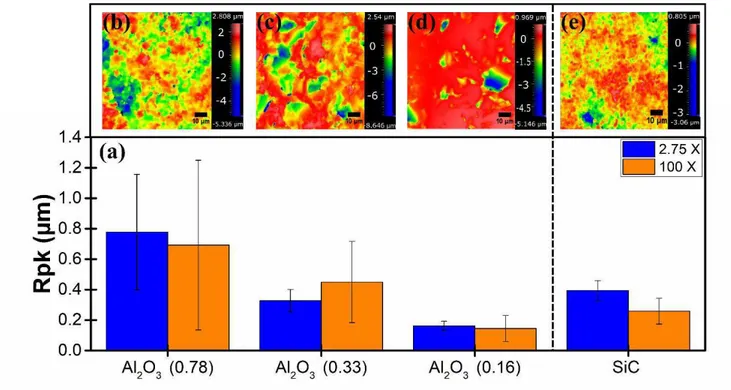
11 The average Rpk values of each sample are shown in Fig. 4a for two magnifications. For all
samples, the standard deviation is larger when measured at a higher magnification. Positioning of grains and pores do not significantly influence roughness at lower magnifications. Higher magnification measurements on a 87x87 μm2 surface area are indicative of the local heterogeneity encountered by splats. High standard deviations in surface roughness measurements may be reflected in variability found in the splat adhesion tests. Single splats encounter various substrate morphologies. Fig. 4 b-e show representative surface topographies of each substrate on a 87x87 μm2 surface area. The as-received substrates are characterised by a series of fine peaks and valleys due to the morphology of the sintered grains. Polished substrates show minimal fine peaks with valleys caused by porosity.
Fig. 4: (a) Surface roughness of Al2O3 and SiC substrates in addition to the surface morphology of (b) Al2O3 (0.78), (c) Al2O3
12
4.2. Splat Adhesion Testing 4.2.1. Adhesion Strength
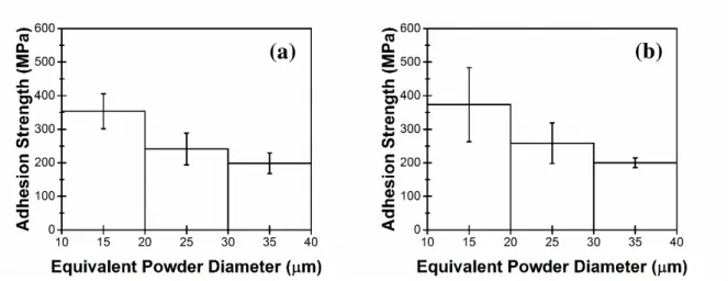
Splats with an equivalent powder diameter spanning nearly the full powder size distribution (Fig. 5) were tested by splat adhesion testing. For the Al2O3 substrates there is a decrease in bond
strength with increase in powder diameter (
Fig. 5). Similar trends were observed for splat adhesion testing of Ti splats deposited on Ti substrates.27 Finer powder particles have higher impact velocities than larger powder particles. The higher impact velocities cause higher adhesion strengths.27, 31, 32 For the SiC substrate, there are 18 splats that resulted in no distinguishable peak. The adhesion strength for these cases was assumed to be zero. From
Fig. 5d null results for the Ti/SiC interface were seen throughout the size distribution. No particular trend or relationship between powder size and probability of a null result was observed for the Ti/SiC interface. For measurable adhesion strengths in the Ti/SiC interface, average adhesion strength appears to be slightly higher than for finer powder particles in the range of 10-20 µm. However, there was no trend of adhesion strength with powder diameter for the Ti/SiC interfaces, which was different from the Ti/Al2O3 interfaces.
13
Fig. 5: Effect of equivalent powder diameter on adhesion strength between Ti and (a) Al2O3 (0.78), (a) Al2O3 (0.33), (c) Al2O3
(0.16) and (d) SiC. (d) includes null results for the Ti/SiC interface as points along the x-axis.
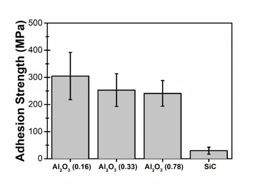
Given the average powder size of 29 μm and the powder size distribution, averages are compared for an equivalent powder diameter between 20 and 40 μm (Fig. 6). Splat adhesion test results showed significantly higher adhesion between all Ti and Al2O3 substrates than between Ti and SiC
substrates. 13 of the 26 tests conducted for the Ti/SiC interface, in this size range, resulted in a null adhesion strength. These results were not included to measure the average adhesion strength.
14
Fig. 6: Average Adhesion strength by splat adhesion testing for powder diameters varying from 20 μm to 40 μm deposited on all substrates with the standard deviation as the error bar.
Al2O3 (0.16) had the highest bond strength. A Student T-test* was used to validate if the bond
strength measurements are significantly different with decreasing surface roughness. The difference between Al2O3 (0.33) and Al2O3 (0.78) was not significant. The difference between
Al2O3 (0.16) and the two other substrates was significant.
4.2.2. Splat Morphology
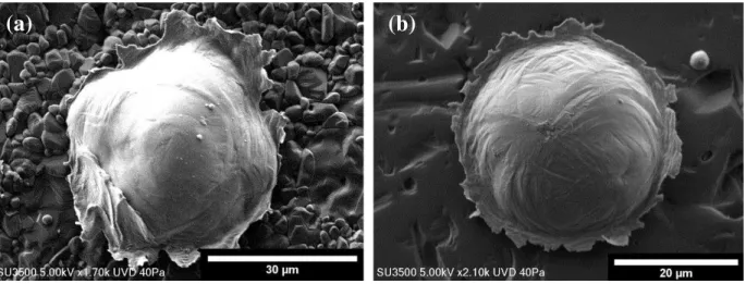
Fig. 7 shows the top view of a single splat deposited on Al2O3 (0.78) and Al2O3 (0.16). Splats
typically show jetting along the edges of the powder due to ASI as commonly observed in cold
* A two-tailed T-test was used given that the number of tests and the variance for each test conditions was not equal. The null hypothesis, that is
the hypothesis that there is no difference between the means, was rejected if the P-value was smaller than 0.05. Therefore, a statement can be made that, despite the standard deviation in the data, the means are statistically different with at least a 95 % level of confidence when the null hypothesis is rejected.
15 spray.3, 5 Losses in kinetic energy required to adapt to the rougher substrate morphology do not cause reduced jetting in the Ti/Al2O3 interface (Fig. 7a). Also, differences in adhesion strength
cannot be identified through splat morphology. Single Ti splats deposited on SiC also show a similar morphology to those deposited on Al2O3, despite their significantly lower adhesion strength
(Fig. 8).
Fig. 7: Single Ti splat deposited on (a) Al2O3 (0.78) and (b) Al2O3 (0.16) showing formation of ASI.
Fig. 8: Impact morphology of a single Ti splat on SiC.
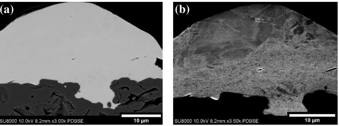
Cross-sectional images between single Ti splats deposited on Al2O3 (0.78) (Fig. 9) and SiC (Fig.
10) showed significant differences despite no observable differences in the plan view splat morphology. Cross-sectional imaging of the Ti splats deposited on Al2O3 (0.78) showed a very
16 continuous interface. The Ti was found to follow the morphology of the substrate even within pores. Fig. 9a shows the interface morphology and Fig. 9b emphasized the grains of the Ti powder through ECC. The material which has penetrated within the pores has nano-sized grains showing evidence of extensive deformation. The material has not melted at the interface. When the rougher ceramic surface is impacted, the fine peaks create a zone of higher pressure due to the reduced surface area at the location of initial impact giving localized plasticity within the impacting powder. When the Ti particle impacts on the rougher Al2O3 substrate, it is locally deformed around
the peaks of the surface, allowing it to penetrate more easily into the pores in addition to the general adiabatic shearing of the particle.33
Fig. 9: Backscattered electron microscopy image of single splat cross-section deposited on Al2O3 (0.78) emphasizing (a)
interface morphology and (b) grain in the Ti splat.
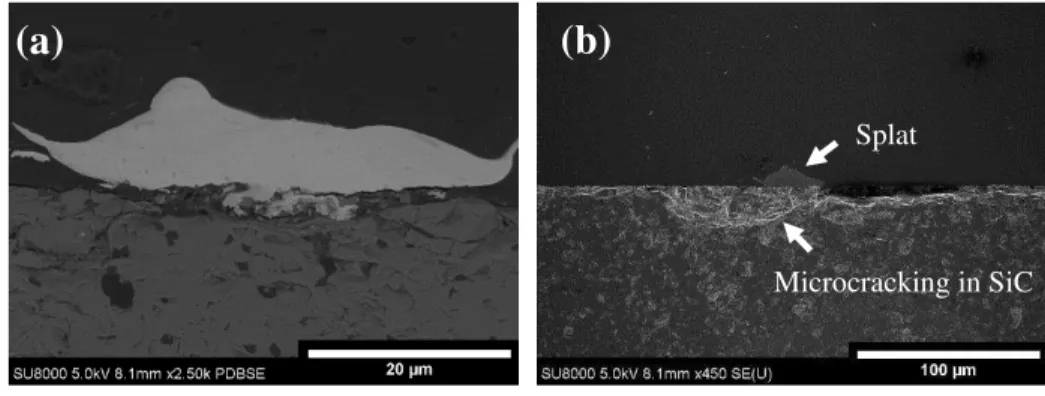
Mechanical cross-sectioning of single splats on SiC (Fig. 10) mainly showed gapping between the splat and the substrate with minor mechanical clamping. The weakly bonded particles allowed the epoxy to penetrate the gap between the splat and the substrate (Fig. 10a). The SiC beneath the splat, in some cases,is more porous than the bulk portion (Fig. 10b). Microcracking from the impact occurs in this region. The higher hardness of the SiC makes it more brittle than the Al2O3.
17 These microcracks cause material beneath the splat to fall during polishing making it appear more porous.
Fig. 10: Cross-section of Ti/SiC interface showing poor bonding. (a) shows a high magnification image to identify interface feature while (b) shows a low magnification image to show cracking in the ceramic substrate.
4.2.3. Post-Test Characterization
Failed interfaces from splat adhesion testing revealed traces of Ti on the substrates. The morphology and quantity of the Ti in the failed interface is indicative of the splat’s bonding mechanism and strength. Color thresholding of LOM images of the failed interfaces was used to determine the relationship between the amount of Ti on the surface and adhesion strength. For the Ti/Al2O3 (0.16) interface, three cases were observable in post-test characterization. Case 1
is characterized by a circular ring of Ti remaining in the failed interface. The adhering ring of Ti does not significantly protrude from the surface of the substrate. Splat which left a ring on the surface of Al2O3 (0.16) impacted areas with minimal porosity. Fig. 11 shows a representative
image of a Case 1 failed interface. Fig. 11 also shows the linear relation with a coefficient of
(b)
Microcracking in SiC Splat
18 determination (R2) of 0.8 between the adhesion strength and the percentage of Ti remaining on the substrate for Case 1.
The surface morphology at the splat level can vary significantly even on the polished substrate due to porosity. Pre-existing porosity in the ceramic substrate or potential induced fracture influenced the morphology of the failed interface. In the presence of large pores, the remaining Ti was found mainly in smooth areas. Fig. 11 shows a representative image of a failed interface of this type, which is designated Case 2. Also, a linear relation between adhesion strength and the amount of Ti in the failed interface was found for Case 2 where fit showed an R2 value of 0.7. The adhesion strength is influenced by removal of Ti from the pore, potential removal of fractured ceramic and shearing of the Ti. For the same percentage of Ti on the substrate, the adhesion strength is higher for Case 2 than Case 1. In Case 1, the shearing of Ti mainly contributes to adhesion strength.
19
Fig. 11: Adhesion Strength with respect to the percentage of Ti remaining on the substrate following splat adhesion testing with regards to the projected splat area for Cases 1 and 2 on Al2O3 (0.16). Representative images of Case 1and Case 2 failed interfaces
on Al2O3 (0.16) are also included.
Case 3 is characterized by a series of fine pores on the surface of Al2O3 (0.16). Fine, weakly bonded
debris of Ti was found to remain on the substrate following splat adhesion testing (Fig. 12). Only a few tested particles resulted in a Case 3 failed interface. Splats had both high and low adhesion strengths in Case 3. No relationship could be established between percentage of Ti on the substrate and adhesion strength.
y = 10.09x + 27.99 R2 = 0.8
y = 15.2x + 77.8 R2 = 0.7
20
Fig. 12: Case 3 failed interface between Ti on Al2O3 (0.16) following splat adhesion testing
The amount and characteristics of the remaining Ti on the surface of Al2O3 (0.33) and Al2O3 (0.78)
were similar. Scattered parts of Ti remained on the substrates where the splat was removed, showing evidence of localized bonding. Representative images are shown in Fig. 13. Ti remaining on Al2O3 (0.78) is mainly within the pores and rarely along the surface of the substrate. These
failed interfaces differ from those in Case 3 on Al2O3 (0.16) as the Ti remaining on the surface
appears well bonded and continuous with the grains of the substrate. From the post-test characterization, it can be concluded that adhesion strength between single splats of Ti on Al2O3
(0.78) is mainly due to mechanical clamping.
The amount of Ti remaining on the substrate varies significantly from one splat to the other. The adhesion strength with respect to the percentage of the Ti remaining on the Al2O3 (0.78) substrate
was also plotted in Fig. 13. It was found that a linear trend with high variance (R2 = 0.45) exists between adhesion strength and quantity of Ti remaining on the substrate. Similarly to Case 2 on the Al2O3 (0.16) substrate, the high variance can be attributed to effects contributing to adhesion
strength measurements such as the extraction of Ti from within pores or detachment of ceramic grains. The adhesion strength for low percentages of Ti on the substrate is higher than what was observed for the Al2O3 (0.16) substrate. However, the splats deposited on Al2O3 (0.16) tend to
21 have a higher percentage of Ti remaining on the substrate, following the test, contributing to its overall higher average adhesion.
Fig. 13: Adhesion strength with respect to the amount of Ti that remains on the substrate following splat adhesion testing for the Al2O3 (0.78) substrate.
The bonding mechanism of Ti particles sprayed on smooth and rough Al2O3 substrates is
significantly different. Mechanical clamping appears to play a more significant role in bonding with the rougher surfaces, but mechanical clamping is not necessarily the only bonding mechanism for cold spraying metal powder on ceramic substrates given the results obtained on the smoother substrates. Bonding also occurs in the zone of ASI, where the temperature is at the highest and deformation is most significant.3, 34 Hence, ASI is likely a necessary occurrence for bonding on
the smooth ceramic substrates.
For the Ti splats deposited on SiC, following splat adhesion testing, there is mainly no evidence of bonding with no Ti remaining on the substrate. Fracture of the substrate is sometimes observable or, in very few cases, a small portion of Ti remained on the substrate (Fig. 14).
y = 5.9x + 199.2 R2 = 0.45
22
Fig. 14: Representative LOM image of failed interface on SiC (a) shows a remaining interface with no evidence of Ti and some minor fracturing of the ceramic identified by an arrow, and (b) shows minor evidence of Ti remaining on the SiC.
BSE images revealed traces of Ti on the surface of the substrate from rebounded or weakly bonded particles which fell off of the substrate. A splat that was removed by splat adhesion testing could not be distinguished from a rebounded splat. These fine traces of Ti were not identifiable by LOM. The traces of Ti remaining on the substrate due to rebounded or detached splats are in the shape of a ring (Fig. 15). Within the ring, the fine traces of Ti appear along the surface and not solely within cracks. This demonstrates that extremely localized bonds are formed within the same area that a complete bond is formed between some Ti splats and Al2O3 (0.16) substrate. An example is marked
by an arrow in Fig. 15. Bonding between Ti and SiC is extremely localized in comparison to Al2O3.
Fig. 15: Circular ring with traces of Ti appearing on SiC in locations where the particle has rebounded or fallen.
23
5. Discussion
5.1. Adhesion strength
Direct comparisons of splat adhesion test to a bulk coating adhesion test are somewhat difficult due to the different length scales and different loading conditions. Splat adhesion test data provides adhesion at the single splat level while typical tensile testing techniques are intended to characterize full coatings. Goldbaum, et al.27showed however that splat adhesion tests correlated well to a bulk coating cohesion measurement for cold sprayed Ti. For metal/ceramic systems, this work represents the first application of the splat adhesion tests. Also, even for bulk tests, there have been no reported bond strength measurements for the Ti/Al2O3 and Ti/SiC interface in
previous literature. However, some qualitative comparisons can be made using other material systems. Few metal coatings deposited on ceramic substrates by cold spray have been tested by bulk coating adhesion tests. Al has been the most prominent metal investigated in metal/ceramic adhesion. Adhesion of Al to MgF2, Al2O3, Si3N4, SiC and AlN at room temperature are all
significantly lower than values obtained here in the Ti/Al2O3 interface. 18, 19, 21, 35 Higher adhesion
strengths are obtained with an increase in substrate temperature and through heat treatment.18, 35
Values remain lower that adhesion between Ti and Al2O3. Bulk coating adhesion tests of Al/SiC
interfaces are comparable to values obtained by splat adhesion testing in the Ti/SiC interface. The bond strength of Ti deposited on Al2O3 is comparable or, in some cases, higher than the values
reported by Goldbaum et al. for Ti deposited on Ti.27 The sheared Ti remaining in the failed interface has been highly deformed at impact, and therefore has a higher shear strength than bulk Ti. The Al2O3 substrate has a higher hardness than a Ti substrate. Thus, the impact onto Al2O3
induces more deformation in the splat than the Ti substrate at impact. This phenomenon can explain the higher adhesion strength measured in certain cases in the Ti/Al2O3 interface. Removal
24 of fractured ceramic grains or surface roughness can also influence adhesion in the Ti/Al2O3
interface.
For metal/metal splat adhesion testing, where the two metals are of the same material, it is impossible to determine the fraction of metal from the splat remaining on the substrate. However, in the work of Goldbaum, et al. they observed that, for their highest adhesion strengths, the test was shearing through the splat very close to the bonded interface.27 This indicates a very good metallurgical bond and the splat adhesion test at this point measures mechanical properties of the splat itself. From post-test characterization of Ti/Al2O3 interfaces, the amount of Ti remaining on
the substrate can be measured and influences the bond strength. Also, the morphology of the remaining Ti provided information with regards to the bonding mechanism. As the tip applies a tangential pressure on the splat, an interface crack spreads leading to the eventual detachment of the splat. The crack spreads through the weakest part of the interface. In the case where crack spreading leaves Ti on the surface of the substrate, it is indicative of a strong bond between the splat and the substrate. The adhesion at the interface is stronger than the cohesion of the splat itself. This was observed when Ti was deposited on Al2O3 (0.16). When deposited on Al2O3 (0.78), the
Ti remained within pores rather than on the surface. The interface was therefore composed of both Al2O3 and Ti. When mechanical bonding is the predominant bonding mechanism shearing of Ti is
necessary to remove the splat. Splat adhesion testing in the rough interface therefore provides a measure of how well the particle is mechanically bonded.
25
5.2. Adhesion Rings
Adhesion between single splats of Ti and smooth substrates was not solely dependent on mechanical clamping. Following splat adhesion testing, a ring of Ti remained on Al2O3 (0.16) in
locations where minimal porosity was observed. Similarly, fine traces of Ti were found in a ring shape when deposited on SiC for rebounded or fallen splats. Various models3, 5, 34 and experimental works27, 36 have shown the link between ASI and adhesion in metallic systems. In splat adhesion testing, a similar ring was previously observed for Ti/Ti and Ti6Al4V/Ti6Al4V interfaces as reported by Goldbaum et al.27 While the center of the powder is exposed to the highest hydrostatic pressure, adhesion does not occur. Rather, shear forces within the adiabatically sheared jet are associated with bonding.8, 22, 36, 37 The presence of a ring of Ti on Al
2O3 (0.16) and on SiC shows
that ASI are significant to bonding in metal/ceramic systems with low surface roughness. Adhesion in the periphery of single splats of Ti deposited onto ZrO2 due to ASI has also previously been
shown.22 Similarly, adhesion rings were observed for Cu/Al2O3 interfaces.11
Drahmann et al.18, 19, as well as Wüstefeld et al.13 and Rafaja et al.17 also suggested that mechanical clamping is not the sole contributing factor to adhesion in metal/ceramic interfaces created by cold spray. Hetero-epitaxy between the metal and ceramic atoms contributes to bonding on mainly atomically smooth single crystal ceramics due to the energy stored in microstructural defects caused during plastic deformation in the metal and heating in the interface.13, 17-19 Rafaja et al. extended the concept of hetero-epitaxy to polycrystalline Al2O3 interfacing Ti, as these materials
show a small lattice misfit along multiple planes.17 On the other hand, Ko et al. attributed adhesion
in metal/ceramic systems to atomic intermixing as a result of amorphisation due to extreme plastic deformation.20 Also, Kim et al. suggested that bonding is attributable to the intimate contact between the metal and the ceramic as surface oxides are removed due to ASI.22 Surface activated
26 bonding is based on the premise that two clean surfaces in intimate contact will form a bond. Clean metal surfaces have a natural tendency to react with oxygen, nitrogen or carbon.38, 39 Metals and oxides have been shown to bond by this technique in their solid-state.22, 38 Here, it was shown that adhesion occurs due to ASI in smooth interfaces. ASI are associated to the location of highest temperature. The previously discussed bonding mechanisms such as hetero-epitaxy, surface activated bonding or atomic intermixing due to amorphisation require atomic motion at the interface. It is therefore consistent that adhesion would occur where ASI are formed by any of these chemical processes.
5.3. Effect of surface roughness
From post-test characterization of single splats deposited on Al2O3 with different surface
roughness, mechanical clamping is observed when peaks and valleys are present. On the rougher substrate, Ti remained between the grains of Al2O3 but for splats on smoother surfaces, a ring
morphology was observed showing evidence of a potential chemical interaction. There are only few studies addressing surface roughness in metal/ceramic interfaces created by cold spray. Images of Al splats deposited on Al2O3 revealed that mechanical bonding assisted in bond formation on
rougher substrate or though porosity on smoother substrates.19 However, a Ti coating on a smooth sapphire substrate was well-bonded while deposition onto a rougher sapphire substrate resulted in delamination.17
Some insight can also be obtained from the literature on metal/metal interfaces. Hussain et al. observed that high surface roughness prevented metallurgical bonding in an Al/Cu interface. Mechanical bonding was the main bonding mechanism.40 Kumar et al. also found that when depositing a soft metal on a hard metal (Al on mild steel), surface roughness influenced adhesion. The bond strength increased with surface roughness until a certain point. For very rough substrates,
27 adhesion decreased. Mixed adhesion mechanisms (metallurgical bonding and mechanical bonding) allowed for high adhesion strength in intermediate surface roughness values.41 Similarly in this work, roughness highly influenced the adhesion mechanism in the Ti/Al2O3 interface. A
transition from mechanical bonding to chemical bonding was observable with decreased surface roughness.
5.4. Effect of substrate composition
Drehmann et al. investigated the effect of the percentage of ionic and covalent bonding in the ceramic on adhesion between the Al and various ceramics in cold spray, as more covalently bonded ceramics tend to be easily wetted by metals. However, higher ionicity of the ceramic did not correlate to higher adhesion strength. Furthermore, poor bonding was not adequately explained by differentces in coefficients of thermal expansion mismatch between the metal and the ceramic. Instead, they proposed that a ceramic’s higher thermal conductivity can assist in the formation of a hetero-epitaxial bond.18 For the Ti splats interfacing with Al2O3 and SiC, a stronger bond was
formed with the more ionic ceramic and therefore further emphasizing that the bond between the cold sprayed metal and the ceramic does not follow the same trend as wetting behaviours between them. Form the manufacturer data sheet, Al2O3 has a thermal conductivity of 30 W/mK and SiC
150 W/mK. The higher thermal conductivity of the SiC did not assist in the formation of a bond. Ti splats deposited on SiC appear to form highly localized, weak bonds. Gaps were found throught most of the interface of the deposited single splats. Drehmann et al. also observed significant gapping between a full coating of Al on SiC and single Al splats on Al2O3 substrate.18, 19 This is
considerably different to what was observed when depositing single Ti splats on Al2O3. The
Ti/Al2O3 interface appeared continuous and rendered very strong bonds under identical spray
28 shows that the impact fracture toughness of the ceramic influences adhesion in cold sprayed metal/ceramic interfaces.
6. Conclusion
A better understanding of metal/ceramic interfaces is necessary to optimize metal matrix composites and for ceramic metallization created by cold spray. Splat adhesion testing provided insight into bond formation between Ti splats deposited on Al2O3 and SiC. The adhesion strength
of Ti deposited on Al2O3 is shown to be significantly higher than SiC. The type of ceramic has an
important influence on adhesion. The Ti/SiC interface showed micro-cracking of the ceramic and gapping while the Ti/Al2O3 interface appeared continuous.
The as-received ceramic substrates had significantly different roughness. Al2O3 was therefore
polished to three final roughness of 0.78, 0.33 and 0.16 µm to investigate the effect of surface roughness on adhesion strength. The bonding mechanism between Al2O3 (0.78) and Al2O3 (0.16)
was significantly different. Splats deposited on Al2O3 (0.78) bonded mechanically with Ti
infiltration into surface pores. Splats deposited on non-porous sections of Al2O3 (0.16) formed
adhesion rings due to ASI. Where large pores on Al2O3 (0.16) were present, Ti remained on the
substrate in the comparatively smooth areas. Some splats landed in areas with fine pores and left minimal Ti on the surface. For the same amount of Ti remaining in the failed interface, splats landing in large pores had higher adhesion strength given influencing factors such as pull out of ceramic grains or Ti from the pores. The amount of Ti remaining on the substrate following splat adhesion testing influences adhesion strength on all Al2O3 substrates.
The failed Ti/SiC interface showed very little evidence of bonding in localized areas. A significant amount of Ti powder rebounded from the substrate leaving rings with fine traces of Ti on the SiC
29 substrate. No traces of rebound were observed on Al2O3 substrates. While ASI lead to a continuous
30
7. References
1. A. Papyrin, Cold spray technology. (Elsevier, Amsterdam; London, 2007).
2. J. Villafuerte, Modern cold spray : materials, process, and applications. (Cham : Springer, 2015). 3. H. Assadi, F. Gärtner, T. Stoltenhoff and H. Kreye, "Bonding mechanism in cold gas spraying," Acta Materialia 51 (15), 4379-4394 (2003).
4. H. Assadi, T. Schmidt, H. Richter, J. O. Kliemann, K. Binder, F. Gartner, T. Klassen and H. Kreye, "On parameter selection in cold spraying," Journal of Thermal Spray Technology 20 (6), 1161-1176 (2011). 5. M. Grujicic, C. L. Zhao, W. S. De Rosset and D. Helfritch, "Adiabatic shear instability based mechanism for particles/substrate bonding in the cold-gas dynamic-spray process," Materials & Design 25 (8), 681-688 (2004).
6. A. Moridi, S. M. Hassani-Gangaraj, M. Guagliano and M. Dao, "Cold spray coating: Review of material systems and future perspectives," Surface Engineering 30 (6), 369-395 (2014).
7. H. Lee, Y. Yu, Y. Lee, Y. Hong and K. Ko, "Cold spray of SiC and Al2O3 with soft metal incorporation: A technical contribution," Journal of Thermal Spray Technology 13 (2), 184-189 (2004).
8. H. Assadi, H. Kreye, F. Gärtner and T. Klassen, "Cold spraying A materials perspective," Acta Materialia Acta Materialia 116, 382-407 (2016).
9. R. R. Chromik, S. A. Alidokht, J. M. Shockley and Y. Zhang, in Cold-Spray Coatings: Recent Trends and Future perspectives, edited by P. Cavaliere (Springer International Publishing, Cham, 2018), pp. 321-348.
10. K.-R. Donner, F. Gaertner and T. Klassen, "Metallization of Thin Al2O3 Layers in Power Electronics Using Cold Gas Spraying," Journal of Thermal Spray Technology 20 (1-2), 299-306 (2011).
11. K. R. Ernst, J. Braeutigam, F. Gaertner and T. Klassen, "Effect of Substrate Temperature on Cold-Gas-Sprayed Coatings on Ceramic Substrates," Journal of Thermal Spray Technology 22 (2-3), 422-432 (2013). 12. B. Wielage, T. Grund, C. Rupprecht and S. Kuemmel, "New method for producing power electronic circuit boards by cold-gas spraying and investigation of adhesion mechanisms," Surface & Coatings Technology 205 (4), 1115-1118 (2010).
13. C. Wüstefeld, D. Rafaja, M. Motylenko, C. Ullrich, R. Drehmann, T. Grund, T. Lampke and B. Wielage, "Local heteroepitaxy as an adhesion mechanism in aluminium coatings cold gas sprayed on AlN substrates," AM Acta Materialia 128, 418-427 (2017).
14. L. L. Hench and S. M. Best, in Biomaterials Science (Third Edition), edited by A. S. Hoffman, F. J. Schoen and J. E. Lemons (Academic Press, 2013), pp. 128-151.
15. J. B. Brunski, in Biomaterials Science (Third Edition), edited by A. S. Hoffman, F. J. Schoen and J. E. Lemons (Academic Press, 2013), pp. 111-119.
16. H. Lee and K. Ko, "Effect of SiC particle size on cold sprayed Al-SiC composite coatings," Surf Eng Surface Engineering 25 (8), 606-611 (2009).
17. D. Rafaja, T. Schucknecht, V. Klemm, A. Paul and H. Berek, "Microstructural characterisation of titanium coatings deposited using cold gas spraying on Al2O3 substrates," Surface & coatings technology.
203 (20), 3206-3213 (2009).
18. R. Drehmann, T. Grund, T. Lampke, B. Wielage, K. Manygoats, T. Schucknecht and D. Rafaja, "Interface Characterization and Bonding Mechanisms of Cold Gas-Sprayed Al Coatings on Ceramic Substrates," Journal of Thermal Spray Technology 24 (1-2), 92-99 (2015).
19. R. Drehmann, T. Grund, T. Lampke, B. Wielage, K. Manygoats, T. Schucknecht and D. Rafaja, "Splat Formation and Adhesion Mechanisms of Cold Gas-Sprayed Al Coatings on Al2O3 Substrates," J Therm Spray Tech Journal of Thermal Spray Technology (5) (2013).
20. K. H. Ko, J. O. Choi and H. Lee, "The interfacial restructuring to amorphous: A new adhesion mechanism of cold-sprayed coatings," Materials Letters Materials Letters 175, 13-15 (2016).
21. S. Kümmel, T. Grund, P. Löschner and B. Wielage, "Influence of Deposition Conditions and Heat Treatment on Tensile Strength of Cold Spray Aluminium Coatings on Al2O3 and AlN Substrates,"
31
presented at the Thermal Spray 2011: Proceedings of the International Thermal Spray Conference, 2011, pp. 26-29.
22. K. Kim, M. Watanabe and S. Kuroda, "Bonding mechanisms of thermally softened metallic powder particles and substrates impacted at high velocity," SCT Surface & Coatings Technology 204 (14), 2175-2180 (2010).
23. A. Sova, V. F. Kosarev, A. Papyrin and I. Smurov, "Effect of Ceramic Particle Velocity on Cold Spray Deposition of Metal-Ceramic Coatings," J Therm Spray Tech Journal of Thermal Spray Technology 20 (1-2), 285-291 (2011).
24. A. Sova, A. Papyrin and I. Smurov, "Influence of Ceramic Powder Size on Process of Cermet Coating Formation by Cold Spray," Journal of Thermal Spray Technology 18 (4), 633 (2009).
25. S. V. Klinkov and V. F. Kosarev, "Cold Spraying Activation Using an Abrasive Admixture," J Therm Spray Tech Journal of Thermal Spray Technology 21 (5), 1046-1053 (2012).
26. R. R. Chromik, D. Goldbaum, J. M. Shockley, S. Yue, E. Irissou, J. G. Legoux and N. X. Randall, "Modified ball bond shear test for determination of adhesion strength of cold spray splats," Surface & Coatings Technology 205 (5), 1409-1414 (2010).
27. D. Goldbaum, J. M. Shockley, R. R. Chromik, A. Rezaeian, S. Yue, J. G. Legoux and E. Irissou, "The Effect of Deposition Conditions on Adhesion Strength of Ti and Ti6Al4V Cold Spray Splats," Journal of Thermal Spray Technology 21 (2), 288-303 (2012).
28. ISO, in Powder metallurgy (2010), Vol. ISO 23519:2010, pp. 5.
29. K. Kim, M. Watanabe and S. Kuroda, "Thermal softening effect on the deposition efficiency and microstructure of warm sprayed metallic powder," Scripta Materialia 60 (8), 710-713 (2009).
30. S. Sömiya and Y. Inomata, "Silicon carbide ceramics--1 : fundamental and solid reaction," (1991). 31. T. Schmidt, F. Gärtner, H. Assadi and H. Kreye, "Development of a generalized parameter window for cold spray deposition," AM Acta Materialia 54 (3), 729-742 (2006).
32. B. Samareh and A. Dolatabadi, "A Three-Dimensional Analysis of the Cold Spray Process: The Effects of Substrate Location and Shape," J Therm Spray Tech Journal of Thermal Spray Technology 16 (5-6), 634-642 (2007).
33. T. Hussain, "Cold spraying of titanium: a review of bonding mechanisms, microstructure and properties," presented at the Key Engineering Materials, 2013, pp. 53-90.
34. G. Bae, Y. Xiong, S. Kumar, K. Kang and C. Lee, "General aspects of interface bonding in kinetic sprayed coatings," Acta Materialia 56 (17), 4858-4868 (2008).
35. R. Drehmann, T. Grund, T. Lampke, B. Wielage, C. Wüstefeld, M. Motylenko and D. Rafaja, "Essential Factors Influencing the Bonding Strength of Cold-Sprayed Aluminum Coatings on Ceramic Substrates," Journal of Thermal Spray Technology 27 (3), 446-455 (2018).
36. M. V. Vidaller, A. List, F. Gaertner, T. Klassen, S. Dosta and J. M. Guilemany, "Single Impact Bonding of Cold Sprayed Ti-6Al-4V Powders on Different Substrates," Journal of Thermal Spray Technology 24 (4), 644-658 (2015).
37. T. Schmidt, F. Gartner, H. Assadi and H. Kreye, "Development of a generalized parameter window for cold spray deposition," Acta Materialia 54 (3), 729-742 (2006).
38. M. Aghasibeig, A. Dolatabadi, R. Wuthrich, C. Moreau, H. Monajatizadeh and P. Bocher, "Cold spray as a novel method for development of nickel electrode coatings for hydrogen production," Int J Hydrogen Energy International Journal of Hydrogen Energy 41 (1), 227-238 (2016).
39. T. Akatsu, N. Hosoda, T. Suga and M. Rühle, "Atomic structure of Al/Al interface formed by surface activated bonding," Journal of Materials Science 34 (17), 4133-4139 (1999).
40. T. Hussain, D. G. McCartney, P. H. Shipway and D. Zhang, "Bonding Mechanisms in Cold Spraying: The Contributions of Metallurgical and Mechanical Components," Journal of Thermal Spray Technology
18 (3), 364-379 (2009).
41. S. Kumar, G. Bae and C. Lee, "Influence of substrate roughness on bonding mechanism in cold spray," Surface and Coatings Technology Surface and Coatings Technology 304 (2), 592-605 (2016).