Development of SiGe arrays for
visible-near IR imaging applications
The MIT Faculty has made this article openly available.
Please share
how this access benefits you. Your story matters.
Citation
Ashok K. Sood, Robert A. Richwine, Yash R. Puri, Nicole DiLello,
Judy L. Hoyt, Nibir Dhar, Raymond S. Balcerak and Thomas
G. Bramhall, "Development of SiGe arrays for visible-near IR
applications", Proc. SPIE 7780, 77800F (2010) © 2010 COPYRIGHT
SPIE
As Published
http://dx.doi.org/10.1117/12.866362
Publisher
SPIE
Version
Final published version
Citable link
http://hdl.handle.net/1721.1/61326
Terms of Use
Article is made available in accordance with the publisher's
policy and may be subject to US copyright law. Please refer to the
publisher's site for terms of use.
Development of SiGe Arrays for Visible-Near IR Imaging
Applications
Ashok K. Sood*, Robert A. Richwine and Yash R. Puri
Magnolia Optical Technologies Inc., 52-B Cummings Park, Woburn, MA 01801
Nicole DiLello and Judy L. Hoyt
Microsystems Technology Laboratories, MIT, Cambridge, MA 02139
Nibir Dhar
DARPA/MTO, 3701, North Fairfax Drive, Arlington, VA 22203
Raymond S. Balcerak
Ray S. Balcerak, LLC, VA 22203
Thomas G. Bramhall
DARPA Programs Office, US Army, AMSRD, Redstone Arsenal, AL 35898
ABSTRACT
SiGe based focal plane arrays offer a low cost alternative for developing visible- near-infrared focal plane arrays that will cover the spectral band from 0.4 to 1.6 microns. The attractive features of SiGe based foal plane arrays take advantage of silicon based technology that promises small feature size, low dark current and compatibility with the low power silicon CMOS circuits for signal processing. This paper will discuss performance characteristics for the SiGe based VIS-NIR Sensors for a variety of defense and commercial applications using small unit cell size and compare performance with InGaAs, InSb, and HgCdTe
IRFPA’s. We will present results on the approach and device design for reducing the dark current in SiGe detector arrays. We will discuss electrical and optical properties of SiGe arrays at room temperature and as a function of temperature. We will also discuss future integration path for SiGe devices with other Silicon-based technology for defense and Commercial Applications.
TECHNICAL DISCUSSION
There is significant interest in developing low cost IR Sensors for a variety of applications such as low cost thermal imagers and the ability to detect and defeat incoming threats. There are several other
technologies such as InGaAs, InSb and HgCdTe, which cover different part of the IR Spectrum. HgCdTe IR focal plane arrays are being developed for 3-5 and 8-14 micron applications [1]. InSb is being used for 3-5 micron applications [2]. Similarly InGaAs offers an attractive approach for Visible-NIR sensors that can cover spectral band up to 1.8 microns [3]. SiGe offers a low cost alternative for developing Vis-NIR sensors that will not require any cooling and can operate from 0.4 to 1.6 micron [4, 5]. The attractive features of SiGe based IRFPA’s will take advantage of Silicon based technology with much larger substrates with up to 10 inch, that can promise very small feature size and compatibility with the Silicon CMOS circuit for signal processing. Large area silicon substrates have the potential of bring the cost down substantially compared with InGaAs. In addition, we will discuss new approaches that can further increase the spectral response to 2 microns and beyond.
*E-mail: [email protected]
Detectors and Imaging Devices: Infrared, Focal Plane, Single Photon, edited by Eustace L. Dereniak, John P. Hartke, Paul D. LeVan, Randolph E. Longshore, Ashok K. Sood, Manijeh Razeghi, Rengarajan Sudharsanan, Proc. of SPIE Vol. 7780 · 77800F · © 2010 SPIE · CCC code: 0277-786X/10/$18 · doi: 10.1117/12.866362
Performance Modeling for SiGe Vis-NIR Sensor
Incendiary events provide large amounts of energy in the SWIR spectral region. Spectrally, muzzle flashes approximate a blackbody spectrum of 800K to 1200K sources, with additional high radiance peaks that can occur at the emission lines for water and for various incendiary chemicals that comprise the propellant. Consequently, smaller pixel sizes can be employed without significantly compromising performance (detection of flash events). Flash durations are in the 1-3 millisecond range, so the full frame time based integration time of 33 msec used for night imaging cannot be used. Since flash events provide such high SNR’s, the spectral bands can be segmented to provide additional information used to identify the threat. Two and three-color outputs can be used to approximate the flash temperature and discriminate live fire from non-threats such as solar or lunar glints. Spectral tags (chemical additives) used for ID of friendly fire can be identified with this two to three-color sensor.
Muzzle flashes consist of an intermediate flash and a brighter secondary flash (unless suppressed) as shown in figure 1.The secondary flash is shown in red and can be approximated as a 1200-1400K blackbody in the SWIR band. The primary flash in blue is approximated as an 800-1000K source. For the flash simulations (SNR plots), a conservative 1000K blackbody source is used.
The dark current numbers used in the analysis were taken from measurements of Ge-on-Si
photodiodes fabricated for high-speed on-chip integrated photonic applications [6]. These diodes were not optimized for imaging applications. The test diodes have sizes in the range of 10x10 to 200 x 200 microns. As the size of the detector is reduced below 10 microns further improvement in the detector dark current is expected, and will improve the sensor performance. These preliminary results show that with SiGe IR Sensor with f/2 optical system, one can detect targets of interest from over 1 km distance. This can have significant applications for a variety of defense missions. The detector sizes investigated here are for SiGe camera with (3, 5 and 7 microns) pixels. These preliminary simulations were performed to show the capability of megapixel SiGe NIR cameras.
As part of the simulations, detector dark currents were varied from 20 to 0.01 nano-Amps (nA). The spectral band used was 0.4-1.6 microns and the average quantum efficiency in the band was 60%. An optical diameter of 2 inches, a focal length of 5 inches, and a 3 micron pixel provide a detector IFOV linear distance of 1.0” at 1 km and, assuming a 2000x2000 format array, an IFOV of 2.7 degrees or 155 feet at 1 km.
Figure 2 summarizes multiple model runs using these parameters. The source radiance simulated is an extended blackbody from 900 K to 1500K which approximates some of the targets of interest. The red plots are for the 3 micron pixel, the green for the 5 micron pixel and the blue for the 7 micron pixel. Muzzle flash (primary and secondary) can be approximated as extended blackbody sources in the 900-1500K.
Figure 1: Plot of Flash Spectra
Figure 2: Signal to noise ratio (SNR) as a function of dark current for SiGe IRFPA for three unit cells
Dark currents in SiGe detectors can be reduced by reducing the pixel size since dark currents track with the volume of the pixel. Reductions in size are advantageous for resolution; however, since the nightglow level is so low, a large pixel size or at least a large collection area is required. If a high density (high fill factor) is achieved in these SiGe arrays, electronic pixel binning of small pixels can be used to achieve a reasonable sensitivity (NEI). If not, a microlens can be used to focus 20-25 micron collection area onto a smaller pixel. These two cases are investigated here using NEI (noise equivalent irradiance) and NEDR (noise equivalent differential reflectance) as performance metrics. NEI is in units of photons/sec-cm2. NEDR is defined as the difference in target reflectance that provides a signal-to-noise of one under “standard” nightglow irradiance. In figure 3, the three plots are for a 20, 10 and 8.5 micron pixel SiGe detector.
Figure 3: NEDR as a function of Dark Current for pixel size of 20, 10 and 8.5 microns for VIS-NIR
spectral band (0.4 to 1.6)
The preliminary analysis shows that a SiGe Sensor with room temperature operation has the ability to detect targets at 1Km and other plume detection at longer ranges. The results clearly demonstrate that SiGe sensor will have a variety of applications for Army missions.
We are evaluating variety of ways to reduce the dark current, while increasing the signal
collection from each of the pixel. One of the approaches that have been used very effectively in HgCdTe and InSb is the use of smaller junction and lateral collection. We have carried out preliminary simulation for the SiGe detector array. Figure 4 presents the plot of SNR vs. dark current for f/2 optics for SiGe sensor with pixel sizes (collection areas) of 15, 30 and 40 um showing improvement in extended target SNR with collection area. We are continuing to refine the model to include smaller detectors such as 5 and 10 micron unit cell sizes. This analysis shows the importance of extending the cutoff wavelength to capture more 900K energy. For hotter sources, the wavelength requirement can be relaxed.
.
Figure 4: Signal to noise ratio (SNR) as a function of dark current for SiGe IRFPA
Measured Characteristics of Ge-on-Si Photodiodes
To efficiently access the VIS-NIR band for various applications, high-Ge-content Si1-xGex (x > 0.5) layers are required. Previous studies have demonstrated Ge-on-Si photodiodes with epitaxial material grown by ultra-high vacuum chemical vapor deposition [7] and by low-pressure chemical vapor deposition [6]. The Ge-on-Si diodes measured in this study were targeted for on-chip photonic
applications, and details of the fabrication are described in [8].
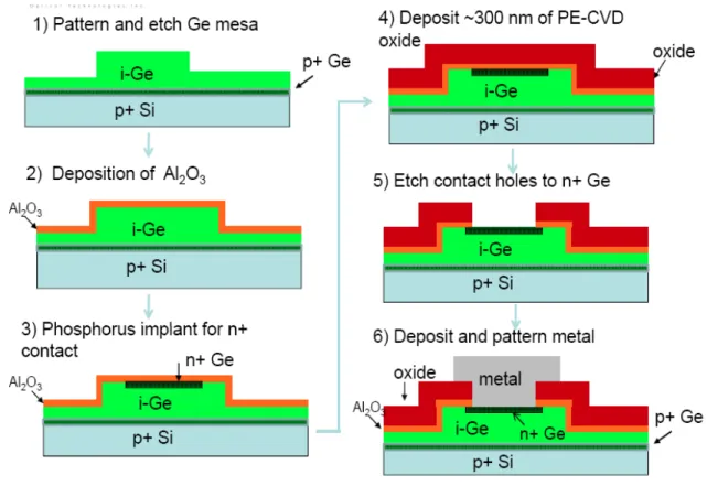
Briefly, the devices are pin photodiodes fabricated in 1.7 μm-thick Ge layers grown directly on 6” Si substrates, using low-pressure chemical vapor deposition in an Applied Materials epitaxial growth system [9]. After Ge growth, standard CMOS processes were used to deposit and pattern a dielectric (SiON) film to open up windows to the Ge surface. Then poly-Si was deposited and implanted with phosphorus to form the n+ top contact. The samples were annealed to out-diffuse the phosphorus into the underlying Ge to form a vertical pin junction in the germanium. A schematic cross-section of these diodes is shown in the inset to figure 7.
Further analysis of these devices indicates that the dark current scales with the perimeter of the device, suggesting that traps along the Ge/dielectric interface are contributing significantly to the leakage current. This analysis motivates further work on materials and processing parameters to improve Ge surface passivation and reduce perimeter leakage currents.
There are a number of potential contributors to the bulk reverse leakage current in Ge-on-Si photodiodes. The dislocations associated with the 4% lattice mismatch between Ge and Si is certainly
one contributor. The threading dislocation density can be reduced by growing the Ge in small areas (with dimensions less than 5 um on a side) by selective epitaxial growth [10, 11]. Furthermore, there is
significant interaction between the poly-silicon contact and the germanium surface during the n+ ion implant activation anneal. This interaction may also contribute to the leakage current. To reduce this effect, the thermal budget should be reduced or the poly-Si contact can be eliminated.
Figure 5: SiGe device configuration for reducing the dark current
Figure 5 presents the SiGe detector design with undoped and doped seed layer. Figure 6 shows the key process steps for fabricating the detector array. Figure 7 presents results of current –Voltage characteristics for 5 micron unit cell with doped and undoped seed. The results show that doping certainly reduces the dark current at room temperature.
Figure 7: Room temperature current –voltage characteristics measurements for small unit cell SiGe
detector with doped and undoped seed.
Figure 8 shows the photoresponse characteristics of the Ge photodiodes measured at a reverse bias of 1 V with no antireflection coating. At 1300 nm, the response is ~0.6 A/W while at 1550 nm; the response has fallen to ~0.45 A/W. The high measured responsivities indicate that these devices will perform well in a variety of system applications.
Further work is underway to determine the device design improvements for further lowering the dark current and hence obtain higher performance for NIR SiGe Sensor. Ongoing studies indicate that by shrinking the size of the device and growing the Ge selectively in small windows, further reduction in leakage current can be attained. We are in the process of fabricating new devices for further evaluating their performance for dark current characteristics using the test structures shown in figure 10.
As the technology for low dark current SiGe detector arrays is developed, further effort will be needed for fabricating high density large format SiGe Vis-NIR focal plane arrays. The front side illuminated process has been developed by DRS for other IR sensor application such as HgCdTe, Si-MEMS based Microbolometers. The process flow shown in figure 9 provides various steps for the fabrication Process.
The fabrication and the integration process shown in figure 13 is shown with Silicon on Insulator (SOI) wafers. The SOI wafers have a thin, CMOS quality silicon layer on top, and a buried oxide layer. Detector p+ base layer and the intrinsic (i) layer are deposited by Si-Ge epitaxy (step1). Vias into Si-Ge are etched by RIE and the buried oxide layer provides the etch stop. Next we deposit an oxide layer to provide dielectric isolation for the via structure. Doped polysilicon deposition completes the top layer (n+) of the photodiode structure (p-i-n) and provides a conductive path to the opposite site of the detector (step 3). A silicon handle is bonded to the detector wafer (step 4) to provide support during the etching and thinning (step 5). The buried oxide layer provides an excellent stop (selectivity > 1000:1) when using EDP for silicon etch. Next, vias are opened though the oxide to access the top detector layer (n+) and the p+ base layer. This step is followed by via metal fill.
Figure 9: Process Flow for fabrication of VIS-NIR Front side illuminated SiGe FPA & CMOS ROIC for
SiGe Sensor and Imager Applications
The detector wafer will be ready for bonding to CMOS. Direct bond interconnect brings to bear state of the art 3-D interconnect technology: wafer scale, low temperature process, highest density of electrical connections and ultra- small pitch, allowing the pixel scale reductions. Following bonding, the handle wafer is removed and pixel isolation etch completes the detector array (step 9).
SUMMARY
SiGe based Vis-IR Focal Plane Arrays offer a low cost alternative for developing near IR sensors that will not require any cooling and can operate in the visible and NIR bands. The attractive features of SiGe based IRFPA’s will take advantage of Silicon based technology, that promises small feature size and compatibility with the low power silicon CMOS circuits for signal processing.
A feasibility study of an infrared sensor based on Ge-on-Si photodiodes indicates promise for IR focal plane arrays with a spectral cutoff wavelength of 0.4 to 1.6 microns. Selective epitaxial growth, reduction of the diode size, and optimization of the diode structure to reduce tunneling leakage are expected to further reduce the dark current in these devices.
ACKNOWLEDGEMENTS
We would like to acknowledge technical discussion with Dr. Arvind D’Souza and Dr. Chuan Li of DRS, Inc. for applications of SiGe devices.
REFERENCES
1. H. Pollehn, K. K. Choi, S. Svensson and N. Dhar “ IR Material Research at the Army research Labs” Proceedings of SPIE, Volume 6542, 65420C ( 2007)
2. J. O. Schlesinger et. al. “ 640x512 InSb Detector Focal Plane Arrays” Proceedings of SPIE, Volume 6542, 6542031 ( 2007)
3. B. Onat, M. Ettenberg et. al. “ Ultralow Dark current InGaAs Focal Plane Arrays” Proceedings of SPIE, Volume 6542, 654206 ( 2007)
4. F.Y Huang, et al. “Normal-incidence strained-layer superlattice SiGe/Si photodiodes near 1.3 um”, Appl. Phys. Letters 67 (4), p. 566 (1995)
5. H. Temkin, et al, “GeSi strained-layer superlattice waveguide photo detectors operating near 1.3 um”, Appl. Phys. Letters 45 (15), p. 963 (1986)
6. F. X. Kärtner, et al. “Electronic Photonic Integrated Circuits for High Speed, High Resolution, Analog to Digital Conversion,” Proceedings of SPIE, 6125 (03), (2006).
7. J. Liu, et al., “Tensile strained Ge p-i-n photodetectors on Si platform for C and L band telecommunications,” Appl. Phys. Letters 87 011110 (2005).
8. O. O. Olubuyide. Low Pressure Epitaxial Growth, Fabrication and Characterization of Ge-on-Si
Photodiodes. PhD Thesis, MIT, 2007.
9. O. O. Olubuyide, et al., “Impact of Seed Layer on Material Quality of Epitaixal Germanium on Silicon Deposited by Low Pressure Chemical Vapor Deposition,” Thin Solid Films, Vol. 508, p. 14 (2006)
10. H-C. Luan, et al. “High-quality Ge epilayers on Si with low threading-dislocation densities,” Appl. Phys. Letters 75 (19), p. 2909 (1999)
11. T.I. Kamins, et al, “Electrical and Structural Properties of Diodes Fabricated in Thick, Selectively Deposited Si/Si1-xGex Epitaxial Layers,” in IEEE Elec. Dev. Letters 13 (4) pp. 177-179, (1992) 12. R. People “Physics and Applications of GeSi/Si Strained Layer Heterostructures” IEEE J.
Quantum Electronics QE-22 (1986), pp. 1696-1986.
13. M. L. Lee and R. Venkatasubramanian “Effect of nanodot areal density and period on thermal conductivity in SiGe/ Si nanodot superlattices” Appl. Phys. Lett. 92, 0534112 (2008).
14. R.M. Kurtz, K.A. Alim, R.D. Pradhan, V. Esterkin, G. D. Savant, R. Venkatasubramanian, M.L. Lee, S. Ghosh, I. Calizo and A.A. Balandin “ High Speed Nano-Optical Photodetector for Free Space Communications” Proc. SPIE 6556 (2007), 6556OH.
15. A.K. Sood, R.A. Richwine, Y. R. Puri, N. DiLello, J. L. Hoyt, T.I. Akinwande, R. S. Balcerak, S. Horn, T. G Bramhall, D. J. Radack, “ Design Considerations for SiGe- based NIR Imaging Sensor” Proceedings of SPIE, Volume 6940, 69400M (2008).