Publisher’s version / Version de l'éditeur:
International Journal of Advanced Structural Engineering, 2018-10-31
READ THESE TERMS AND CONDITIONS CAREFULLY BEFORE USING THIS WEBSITE.
https://nrc-publications.canada.ca/eng/copyright
Vous avez des questions? Nous pouvons vous aider. Pour communiquer directement avec un auteur, consultez la
première page de la revue dans laquelle son article a été publié afin de trouver ses coordonnées. Si vous n’arrivez pas à les repérer, communiquez avec nous à PublicationsArchive-ArchivesPublications@nrc-cnrc.gc.ca.
Questions? Contact the NRC Publications Archive team at
PublicationsArchive-ArchivesPublications@nrc-cnrc.gc.ca. If you wish to email the authors directly, please see the first page of the publication for their contact information.
NRC Publications Archive
Archives des publications du CNRC
This publication could be one of several versions: author’s original, accepted manuscript or the publisher’s version. / La version de cette publication peut être l’une des suivantes : la version prépublication de l’auteur, la version acceptée du manuscrit ou la version de l’éditeur.
For the publisher’s version, please access the DOI link below./ Pour consulter la version de l’éditeur, utilisez le lien DOI ci-dessous.
https://doi.org/10.1007/s40091-018-0204-2
Access and use of this website and the material on it are subject to the Terms and Conditions set forth at
Simplified finite element model for evaluation of ultimate capacity of
corrosion-damaged reinforced concrete beam-columns
Mohammed, A.; Almansour, H.; Martín-Pérez, B.
https://publications-cnrc.canada.ca/fra/droits
L’accès à ce site Web et l’utilisation de son contenu sont assujettis aux conditions présentées dans le site LISEZ CES CONDITIONS ATTENTIVEMENT AVANT D’UTILISER CE SITE WEB.
NRC Publications Record / Notice d'Archives des publications de CNRC:
https://nrc-publications.canada.ca/eng/view/object/?id=f781c967-b4c1-4658-9233-8308cba73aa1 https://publications-cnrc.canada.ca/fra/voir/objet/?id=f781c967-b4c1-4658-9233-8308cba73aa1
https://doi.org/10.1007/s40091-018-0204-2
ORIGINAL RESEARCH
Simpliied inite element model for evaluation of ultimate capacity
of corrosion‑damaged reinforced concrete beam‑columns
A. Mohammed1 · H. Almansour1 · B. Martín‑Pérez2
Received: 5 October 2017 / Accepted: 5 October 2018 © The Author(s) 2018
Abstract
A simpliied nonlinear inite element analysis (NLFEA) based on enhanced inspection, material testing, and nonlinear sec-tional analysis is introduced as part of a semi-quantitative assessment approach of aged beam-columns. The focus is on the evaluation of the structural performance and residual capacities of slab-on-girder bridge columns subjected to combined external loads and reinforcement corrosion. NLFEA takes into account diferent levels of geometrical, material, and bond damage due to reinforcement corrosion. At each load step of the nonlinear analysis process, NLFEA establishes the instanta-neous stifness of the structure through efective transfer of the instantainstanta-neous axial and lexural rigidities from the sectional level to the element level. The model adopts a displacement ield tuning convergence approach that involves single or multiple correction phases satisfying the equilibrium and any user-deined displacement tolerance. The eiciency and accuracy of the proposed NLFEA is veriied by comparison with test and analytical results from previous studies conducted on undamaged and corrosion-damaged structural elements. NLFEA proves to have high numerical stability and fast convergence, establish-ing its adoptability in large structural analysis/assessment frameworks. For corrosion-damaged beamcolumns, it is found that critical design sections do not necessarily remain critical for the structural evaluation.
Keywords Nonlinear inite element analysis · Reinforcement corrosion · RC bridge column · Semi-quantitative assessment
framework · Displacement ield tuning convergence
Introduction
A signiicant percentage of North American infrastruc-ture, speciically bridges, are reported deicient (Lounis et al. 2010), while limited public resources are available for their maintenance/rehabilitation. The qualitative assess-ment approaches adopted by diferent states in the US or diferent provinces in Canada are based on periodic visual inspections (usually every 2 years). With variable inspectors’
experience, it is diicult to have an accurate rating of the bridge status, where an evaluation of the residual ultimate and service capacities of a critical bridge is not performed. When a bridge is identiied as deicient and its load capacity is questionable, a simpliied evaluation approach, if avail-able, can help practicing engineers and bridge owners to have a better quantitative base for their management deci-sions. The increasing gap between the deterioration demand and available resources raises the need to develop a practical yet eicient quantitative assessment (evaluation) framework (QAF). The development of such an evaluation approach requires the development of accurate structural analysis models that are capable to estimate both the time-dependent deterioration of ultimate capacities of critical bridge ele-ments as well as the bridge allowable service loads.
Most of North American bridge infrastructure that was built during the development boom from the 1950s to 1970s has diferent levels of deterioration, and their safety and serviceability are susceptible. Present infrastructure management systems mainly rely on qualitative evalua-tion approaches, where the bridge structural performance
* A. Mohammed amina.mohammed@nrc-cnrc.gc.ca H. Almansour husham.almansour@nrc-cnrc.gc.ca B. Martín-Pérez beatriz.martin-perez@uottawa.ca 1
Civil Engineering Infrastructure, National Research Council Canada, 1200 Montreal Road, Building M-20, Ottawa, ON K1A 0R6, Canada
2 University of Ottawa, CBY A306, 161 Louis Pasteur, Ottawa,
status is judged through routine visual inspection (usually every 2 years). If a “severe” deterioration case is captured, more reined inspection is conducted. The bridge manage-ment systems (BMS) in North America and many other countries around the world are based on identiication of four general condition states under which the bridge ele-ments are categorized. The four condition states are (1) Excellent, (2) Good; (3) Fair; and (4) Poor (see Ministry of Transportation 2008 and American Association of State Highway and Transportation Oicials 2007). The accu-racy of bridge rating and management decisions of bridge engineers reliy on the accuracy of the bridge condition assessment (Rashidi and Gibson 2012), mainly based on diferent levels of visual inspection. Diferent bridge man-agement systems recognize many types of visual inspec-tion such as the typical visual inspecinspec-tion (VI), in-depth VI, and enhanced in-depth VI (see FHWA-RD-01-020, Min-istry of Transportation 2008 and American Association of State Highway and Transportation Oicials 2000). The comparison of bridge inspection standards among various international organizations indicates that each organization has a diferent approach to bridge inspection in terms of the types of inspection, the frequency of the inspections, the deinition of the various inspection types, and the type of personnel that undertakes the inspections (Brown et al.
2010). The lack of a practically simple and cost-efective quantitative assessment approach that is capable to accu-rately determine the state of the performance in terms of safety and serviceability of critical bridge elements is now identiied as a major research gap.
Reinforcement corrosion has been identiied as the major cause of the deiciency of structural capacity and ductil-ity of reinforced concrete (RC) infrastructure. The initia-tion and progression of corrosion in reinforcing steel can have unlimited number of scenarios that are yet not fully understood. It is very challenging to develop time-dependent analytical models that are capable to accurately estimate the efects of all diferent reinforcement corrosion scenarios on the structural behavior of damaged RC elements. Instead, a simplified and practical semi-quantitative assessment (evaluation) framework (SQAF) can be developed. Visual inspection enhanced with some measurements of the damage zones and selected material testing can provide a relatively accurate data for the SQAF. In the absence of enough test results, empirical formulae can be used to estimate the mate-rial properties of the steel and the related level of damage. The SQAF should address the major evaluation limit states of corrosion-damaged bridge elements that are consistent with existing bridge design codes: ultimate limit state (ULS) including seismic loads (for high risk zones), and service-ability limit state (SLS) (Canadian Standards Association (2006), or American Association of State Highway and Transportation Oicials 2007).
The advances in experimental investigation enable better understanding of the damage and failure mechanisms of RC structures under extreme external loads (Mohammed 2014). The objective of this paper was to present the development of a simpliied non-linear inite element analysis approach (NLFEA) to simulate the structural behavior of corrosion-damaged RC elements. The input data for the NLFEA come from an inspection enhanced with some measurements and material testing, whereas the nonlinear inite element approach is based on the nonlinear sectional analysis devel-oped by the authors (Mohammed 2014). The inspection pro-vides input data about the location and size of the damaged zone and the level of damage, while material testing enables the evaluation of the instantaneous material properties at the time of the assessment. NLFEA can serve as the basis of the SQAF, where the aged/damaged bridge load capacity can be estimated. The focus of the study is on the structural behavior of aged bridge beam-column elements such as: (1) the columns are the most critical elements for the stability and robustness of bridge structures; and (2) beam-column elements are the most general frame elements that simu-late the behavior of beams, columns, or beam-columns, and hence they can be adopted in modeling buildings as well (e.g., parking garages).
This NLFEA requires the use of an eicient elasto-plastic nonlinear model that takes into account diferent levels of geometrical, material, and bond damage due to reinforce-ment corrosion at the section level. In order to establish the instantaneous element stifness, and hence the global stif-ness of the structure at each load step, the instantaneous axial and lexural rigidities at the sectional level are to be efectively transferred to the element level in the NLFEA. Furthermore, the NLFEA has to safely match the available experimental and/or ield test results for the case of external loading without corrosion and for the case of combined load and reinforcement corrosion. However, it has to be simple, numerically stable, and able to be integrated into the pro-posed SQAF procedure:nonlinear inite element analysis (NLFEA) as a part of proposed semi-quantitative assess-ment framework (SQAF).
The proposed SQAF (see Fig. 1) has six parts: (1) input data; (2) quantiication of reinforcement corrosion and its efects on the damage zone and materials’ properties; (3) evaluation-ULS: evaluation of columns’ performance under combined corrosion and ultimate loads; (4) evaluation-SLS: evaluation of columns’ performance under combined corro-sion and traic loads; (5) evaluation-ULS-EQ evaluation of columns’ performance under corrosion and ultimate seismic loads as part of evaluation-ULS, only in high-risk seismic zones, (Canadian Standards Association 2006) (CAN/CSA-S6-14); and (6) semi-quantitative assessment and reporting. The NLFEA plays the most important role in the proposed SQAF. It performs the three major parts of the evaluation:
evaluation-ULS and evaluation-ULS-EQ (part III and part V), and evaluation-SLS (part IV). The evaluation of the col-umn structural performance under combined reinforcement
corrosion and traic loads and the evaluation of the column structural performance under combined reinforcement corro-sion and seismic loads are presented by Mohammed (2014).
It has to be noted that the fatigue limit state (FLS) is consid-ered as out of the scope of this study.
The irst part of the proposed SQAF includes three data-input tasks: (I-a) the structural material and geometrical data including boundary conditions; (I-b) the loading data; and (I-c) the enhanced inspection data (reinforcement corrosion damaged zones). In the irst task, the data are collected from the original design information/sketches (if available) and the ield tests on the materials (if possible). The diference between the original design loads and the present loads on the bridge column under consideration is to be determined. The enhanced inspection can provide very important meas-urements and details that can identify the state of corrosion-afected or -damaged zones. The deterioration of the struc-tural parameters is then re-evaluated quantitatively through the NLFEA as shown in the following sections.
The proposed SQAF identiies four major damage cases due to the reinforcement corrosion, as shown in Fig. 2: (II-a) corrosion concrete cracking; (II-b) concrete cover spalling (number 5 in Fig. 2); (II-c) failure of one or more stirrups (number 6 in Fig. 2); and (II-d) a more advanced state of corrosion progress that would lead to the structural failure through complete loss of the coninement or rebar buckling (number 7 in Fig. 2). The details of each of these major pos-sible deterioration states are shown in Fig. 2.
The ULS is interactively integrated with step (II) above, where at each major corrosion efect case; the lowchart shows an end-link to the NLFEA (see Fig. 2). For instance, NLFEA is the basis of four evaluation-ULS tasks: (III-a) establishing the load–displacement relationship; (III-b) establishing the moment–curvature relationship; (III-c) eval-uating the load capacity deterioration compared to the state of no damage; and (III-d) evaluating the structural ductility deterioration. These four tasks of evaluation-ULS end with the preparation of the required data for the SQAF.
Modeling the efects of reinforcement corrosion at the element level
Reinforcement corrosion can lead to different damage mechanisms in the steel and the surrounding concrete in the afected zones. Corrosion-induced damage results in signii-cant change of the concrete and steel strength and ductility, deterioration of the composite action and integrity at the section level, and hence a reduction in the axial and lexural stifnesses. If local damage afects a critical lexural or shear zone, the structural capacity of the RC element based on sec-tional analysis can signiicantly decrease. In this paper, the investigation on the efects of reinforcement corrosion on the structural behavior is for overall structural-element level and comprehensively integrates these efects into the NLFEA.
In order to present the combined efects of reinforcement corrosion (with the possible damages) and external loads
into the proposed nonlinear inite element approach, Fig. 3
shows a beam-column element subjected to axial force and bending moment. Figure 3a shows a possible general load-ing, boundary condition, and reinforcement of a beam-col-umn element. In most practical cases, bridge colbeam-col-umns are subjected to eccentric axial loads, where lexural cracks form at the maximum moment zone. If the external moment is constant over the column height and the axial load is domi-nant (no tensile stress is developed on any section along the beam-column), then no lexural cracks would develop. How-ever, the high axial load could result in cracks due to lateral expansion (Poisson’s ratio efect). The bridge columns are conservatively designed for a lower bound service-to-ulti-mate loads ratio; hence service to ultiservice-to-ulti-mate load capacity of columns is in the range of 25–50%. If the external moment is high enough to generate tensile stresses in one of the column side faces, then lexural cracks develop laterally parallel to each other and distributed over the column height. When reinforcement corrosion is initiated over the main rein-forcement, as shown in Fig. 3b, then corrosion cracks could develop parallel to the rebars, crossing lexural cracks. An accelerated cover spalling could take place if both cracks are developed at the same time. If corrosion continues to pro-gress, more longitudinal cracks can develop, and the local corrosion damage of the surrounding concrete could lead to local loss of bond followed by spalling of the concrete cover as shown in Fig. 3c. In addition, uniform loss of the rein-forcement cross-sectional area over the corrosion-damaged zone takes place. The properties of the steel also change with the progress of corrosion. It has to be noted that the case of local severe reduction of the cross-sectional area of some rebars due to pitting corrosion is not discussed in this study. The mentioned changes could result in a large decrease of the axial and lexural sectional rigidities. Further progress of the corrosion process could result in some stirrups failure (rebar fracture), as shown in Fig. 3d, and this would increase the local spacing between the lateral ties. This would result in a reduction of the coninement of the core concrete, and hence the overall stifness and strength of the column, spe-ciically in the critical damaged zones, would be reduced. In relation to the inite element discretization, three types of elements are distinguished in beam-columns with local cor-rosion damage: (1) no-corcor-rosion damaged zone; (2) partly corrosion damaged or corrosion-transition zone; (3) fully corrosion damaged zone (see Fig. 3e).
Reduction in reinforcement cross‑sectional area and ductility, and loss of concrete cover
The changes in geometrical properties of the corrosion-dam-aged zones and in the materials properties of the steel and the concrete at the section level are shown by Mohammed (2014). Each element in the inite element analysis at the
structural level has its geometrical and material properties as the average properties of its characteristic sections that are evaluated at the sectional level. The instantaneous element
stifness estimated at each load step is based on the equiva-lent average of the axial rigidities and the equivaequiva-lent average of the lexural rigidities of all characteristic sections of that
Fig. 2 Evaluation of column performance under corrosion and ultimate loads. Evaluation of column performance under corrosion and ultimate
Establish load displacement relationship based on multiple deterioration levels
Establish crack pattern based on multiple deterioration levels Proposed nonlinear finite element analysis (NLFEA)
See Fig.6
Maximum load capacity & its effect on permitted traffic load
Load over capacity change in deformation pattern & ductility
Prepare required data for final quantitative assessment of bridge column Evaluate column performance under
corrosion & ultimate loads
2
2
Bar Buckling
Bar Buckling Loosing Confinement
Main bar & stirrups area loss, cover losses, bond loss, confinement loss & bar Buckling Main bar & stirrups area loss, cover losses,
bond loss & confinement loss 7
Final stage of Deterioration & Failure
2 or 3 or 4
element. Hence, the damage and the change in the material properties at the section level are transferred to the element level through the average changes in the instantaneous ele-ment stifness.
Loss of bond in the corrosion afected zone
The background and the deterioration mechanisms of the rebars-to-concrete bond are discussed in detail by Moham-med (2014). It has been proven if the bond stresses outside
the “bond failure zone” do not exceed the bond strength, then an arch mechanism is developed provided that the ends of rebars are adequately anchored. If no progressive bond failure takes place, then the possibility of high deforma-tions due to loss of bonding action is reduced. A proposed approach to estimate the efects of the local bond loss due to corrosion on the redistribution of the stresses/forces acting on the cross sections is presented in Mohammed (2014).
The equilibrium of forces in the characteristic sections of the bond failure zone of lexural members is not directly
(a) (b) (c) (d) (e)
Fig. 3 Possible damage and failure modes of an RC beam-column
due to combined gravity loads and corrosion; a schematic drawing;
b lexural and corrosion cracks; c spalling on tension side; d
stir-rup failure; e beam-element discretization: (i) no corrosion damaged zone, (ii) partially corrosion-damaged zone, (iii) fully corrosion-dam-aged zone
satisied (at the section level). An arch action is developed over three zones: the corrosion damaged zone and two adjacent zones that are not afected by corrosion where the equilibrium is being satisied along the three zones (see Fig. 4a). The tensile reinforcement passing through the three zones and the distributions of the tensile and bond stresses are shown in Fig. 4a, where the excessive expan-sion of the corroded regionmakes additional bond stresses “migrate” from the damaged to the undamaged zones, and
balancing compressive stresses are developed in terms of an arch action. In all sections where bond is active, compressive and tensile forces act as a couple to rotate the cross-sections around the neutral axis (Euler–Bernoulli beam theory). In the other cross sections where bond has failed, the inter-nal forces acting on the sections satisfy equilibrium only in the RC structural element across the three zones (i.e., “bond failure zone” and the two neighboring “active bond zones”). Since the tension and compression forces acting on
Fig. 4 Formation and migration
of bond stress “wave” through-out formation and progression of local bond failure due to corrosion
the section are not balancing each other across the section itself in the “bond-failure” zone, then two additional inclined compressive forces develop in the two side zones forming an arch, which is self-supported by the tensile force in the steel. As corrosion begins and propagates, the loss of bond is also extended along the reinforcement. While the bond loss region is expanding, bond stresses increase at the two ends of the bond failure zone, forming a high-stress transition zone where the stress redistribution takes place. Figure 4b (1) through (3) shows the migration of high bond stress waves when the corrosion-induced bond loss zone expands longitudinally, where: (1) BAZ is the length of the bond afected zone of the rebar; and (2) BSD is the constant bond stress after stress re-distribution takes place. With a very high level loading case, where the load exceeds the service load but is still less than the ultimate load, further propaga-tion and migrapropaga-tion of the bond loss zone beyond that devel-oped due to corrosion would likely take place. The addi-tional bond stress due to the high increase of external loads would increase the peak stress of the “bond stress waves” at the transition regions, which could result in a progressive loss of bond leading to sudden failure.
With a signiicant sectional loss in tensile reinforcement, and if the tensile stresses in the afected steel are relatively high (beyond yield but still under the ultimate stresses), high local axial deformations in the tensile reinforcement are expected. This would result in widening of the lexural cracks, accelerating the local damage and concrete spalling. Furthermore, the formation of an arch action would increase the compressive stress in the “bond-failure” zone. When the structural member is subjected to axial compression in addition to bending moment (in beam-columns), the tensile stresses in the tensile steel could be signiicantly reduced. Hence, the stress redistribution mechanisms could not be developed, and the efects of losing the bond in the corrosion afected zone could marginally afect the lateral deforma-tions. In the present study, the focus is on beam-columns of slab-on-girder bridges that are subjected to axial load and moment as a result of the load eccentricity. For the proposed NLFEA, the equilibrium is satisied at the sectional and the element levels taking into account the redistribution of the stresses due to the formation of the arching action, checking whether the bond stress level exceeds the bond strength in non-corroded zones (active bond zone as shown in Fig. 4a).
Loss of stirrups and concrete coninement, and longitudinal rebar buckling
At advanced corrosion stages, fracture of critical stirrups in corrosion-damaged zones is widely observed, which could result in premature buckling of the main rebars (Rodríguez et al. 1996). In lexural members, severe localized corrosion or pitting corrosion could develop in zones that are located
away from critical moment or shear sections. The reduction in structural capacity due to stirrup corrosion could be spe-ciically serious in RC columns, as they provide coninement to the core concrete in addition to their major contribution to shear resistance. This signiicant efect of losing stirrups due to corrosion on the axial and bending moment carrying capacities of deteriorated RC columns has been observed by Rodríguez et al. (1996) and Oyado et al. (2007). NLFEA of RC beam-columns is subjected to external loads and rein-forcement corrosion.
The nonlinear inite element analysis approach is pre-sented here. This section includes the background assump-tions, the nonlinear approach steps, and the “displacement ield tuning convergence” (DFTC) technique.
Assumptions
The NLFEA is based on the following assumptions: (1) concrete and steel are isotropic materials; (2) the “local” stifness matrix (with its 6 × 6 entries related to 3 degrees of freedom for each of the two nodes in the inite element) is established from the equivalent average of the axial and the lexural rigidities calculated over all characteristic sections of that element; (3) the lexural rigidity of each section is calculated from the base sectional analysis (see Mohammed
2014); (4) all deformations (displacements, rotations, etc.) are continuous functions over the discretized continuum (i.e., the structural element) throughout all load steps; (5) Euler–Bernoulli beam theory is applicable and the efect of stress redistribution due to bond loss is added; and, (6) equilibrium should be satisied at both the section and struc-tural levels.
Discretization
The NLFEA is following the typical inite element discre-tization of linear structural members. The column is divided into a number of inite elements of constant or variable length. The number of characteristic sections is optimized depending on the length of the member, the number and length of the inite elements, and the length of the corrosion damaged zone. The location of each characteristic section is identiied based on the variation of the sectional properties and the required accuracy. In Fig. 4a, element (j) joins node (i) and node (i + 1), and it includes as an example three char-acteristic sections (k), (k + 1), and (k + 2). Two approaches can be followed to select the number of elements and num-ber of sections per element: (1) if the required processing time and the size of the structure are large, then the smallest possible number of elements with a reasonable number of sections per element has to be selected; or (2) if the variation
of stresses is very high or the change in properties due to corrosion progress is signiicant, then selecting a large num-ber of elements with a minimum numnum-ber of sections is the best approach. A reined analysis is also possible when the preliminary trials raise the need to capture the steep vari-ation of the displacements or stresses in a speciied zone of the structural element. Whatever discretization approach is followed, ine tuning of the convergence parameters on a case by case basis is a key for an eicient modeling, as shown in the following sections.
Nonlinear inite element procedure
In order to achieve an acceptable model performance and accurate results, the simpliied NLFEA has to show the fol-lowing: (1) numerical eiciency in terms of minimum use of random access memory (RAM) and minimum process-ing time; (2) highly controlled and systematic convergence with minimum sensitivity; and (3) minimum time and num-ber of trials in idealizing and discretizing. The baseline for an acceptable model performance is the simplicity of its structure, the matching to available experimental results, and numerical eiciency in terms of computing time and memory use. Throughout the evolution of nonlinear inite element analysis of RC frame structures (see Mohammed et al. 2012), the nonlinear (material, geometrical or both) element stifness was derived using analytical approaches with closed-form integration, semi-analytical approaches,
or numerical integration. High-numerical sensitivity and time-consuming convergence have been experienced when closed-form nonlinear formulation has been used. At the early development of non-linear inite element models, the use of numerical integration for each section at each load step was not an option, as it requires large memory and com-putational time.
The NLFEA presented here employs a numerically ei-cient nonlinear sectional analysis (NLSA) (see Moham-med 2014 for the details of derivation and veriication). In addition, the model involves the use of “displacement ield tuning convergence” or DFTC. DFTC is an innovative convergence approach where the trial and errors process to verify equilibrium at the element level is controlled by correcting the displacement vector based on the correc-tion of the maximum displacement normal to the axis of the structural element. The correction is based on propor-tioning the change in the displacement in successive load increment steps and correction trials. The corrections of all deformations are assumed linearly proportional to the correction of the maximum deformation. This approach was originally developed by Almansour (1988) for non-linear analysis of plates and shells and simpliied here for the application to RC frame structures. Figure 5 shows the trial deformation ields and successive corrections (corr
i, corr i+1, corr i+2,…., corr i+n), where the deformation
ield is corrected successively until equilibrium is satis-ied, allowing very small tolerance in the tuning process.
For simplicity and conceptual purpose only, the igure shows that the corrected displacement curve is succes-sively moving in one direction only, which is not always the case in the trial and error process. Figure 6 shows the NLFEA procedure assuming constant increments of the load throughout. The procedure is as follows:
1. For irst applied load increment, Pi=1 = ΔP:
(i) Find the structural stifness, Ki=1 based on linear
inite element analysis.
(ii) Solve Pi=1 = Ki=1Ui=1 for the global structural
deformation vector, Ui=1.
(iii) Identify the maximum vertical displacement over the deformation ield (deformation vector)
Vi=1.
(iv) Find the element forces and hence the sectional forces involving bond loss efects at the element level.
(v) Perform nonlinear sectional analysis based on the results of step one to deine the rigidities at
the section level, and hence the stifness for next step.
(vi) Check if the section has failed.
2. For any subsequent load increment, Pi+1 = Pi +ΔP
(i) Construct the nonlinear stifness matrix based on the sectional properties of each element in the previous load step, Ki.
(ii) Solve Pi+1 = Ki Ui+1 for the global structural
deformation vector, Ui+1.
(iii) Identify Vi+1 and calculate the correction, Corr-i,
which is found as (maximum Vi+1 − maximum Vi1)/maximum Vi, where maximum Vi should
be compared to the tuning variable, α, which is introduced to control “tune” the convergence. (iv) The modiication of the deformation vector is
assumed linearly proportional to the maximum displacement normal to the structural member axis, Uicorr−i = Ui * (1 + Corr−i). That is, it
cor-responds to the maximum displacement, Vicorr−i.
(v) Check the tolerance for the displacement. (vi) If the tolerance is not satisied, initiate a
sec-ond cycle of correction based on the instan-taneous diference in the force vector, or, Fi dif = P
i+1 − Kicorr Ui+1corr.
(vii) Solve, Fidif = Kicorr×Ui+1_difcorr for Ui+1_difcorr.
(viii) Find the element using the present element deformation vector, Uicorr−i+1 .
(ix) Find sectional forces and properties using the present element properties.
(x) Perform nonlinear sectional analysis to ind the stifness for next step.
(xi) Check for section failure (concrete crushing in the compressive zone or tensile failure of the steel in the tensile zone).
(xii) Re-assemble the instantaneous corrected stif-ness matrix and solve the inite element matrix equilibrium equation for displacement and then ind the maximum displacement at this correc-tion sub-step.
(xiii) Check the tolerance until satisied; otherwise, establish a new correction cycle.
(xiv) If the tolerance is satisied, save the results and increase the load.
It is important to mention that the above proposed proce-dure recognizes the direction of the reference displacement component (normal or parallel to the structural element axis) for the use in DFTC based on the direction of the dominant load. If the external moments due to eccentricity or bending moment due to lateral loading are controlling the structural behavior (where the lexural stresses are signiicantly higher than the axial stresses, such as in beams), then the tuning is based on the maximum deformation normal to the struc-tural member. If the external axial load generates sectional stresses that control the behavior (column action), then the tuning is based on the maximum deformation in the direction of the structural member.
Case studies
Five case studies are presented in the following section, four of which are to verify the performance and accuracy of the proposed NLFEA against experimental results in the lack of ield data collected from existing bridges; the ifth is to show the capability of the model to analyze a beam-column under diferent loading cases. Two of the four veriication case studies correspond to structural elements subjected to only external “mechanical” loads; however, in order to investigate the efect of the corrosion damage in critical lexural zones, a corrosion-damaged zone is added to each of the two case studies (as shown below). The other two veriication case
studies correspond to structural elements that are subjected to combined external loads and reinforcement corrosion.
Veriication of the proposed model for the case of non‑damaged structure
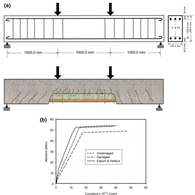
In the irst case study (case study I), a simply supported beam subjected to four-point loading is loaded up to failure as shown in Fig. 7a (Rasheed and Dinno 1994a). The beam is modeled to verify the accuracy and numerical stability of the proposed NLFEA. The beam is 3.0 m long and has a cross section of 152.4 mm by 280.0 mm, with 29.2 mm and 34 mm as bottom and top concrete covers, respectively. The beam is doubly reinforced at the top and bottom faces by three carbon steel rebars of 14-mm diameter on each side, as shown in the cross section of Fig. 7a. The com-pressive strength of the concrete is f’c = 41 MPa. For the steel, the modiied tri-linear expressions of the stress–strain relationship of black steel adopted from Yalcin and Saat-cioglu (2000) are used. The beam is modeled for veriica-tion purposes, by comparing the inite element results to the original experimental results in terms of the moment versus mid-span curvature for the case when the beam has no corrosion damage. To extend the analysis to include cor-rosion damage, reinforcement corcor-rosion is assumed to occur along the middle third of the beam span at the tension zone. Figure 7a shows the location and the expected damage due to corrosion.
Figure 7b shows that the moment versus mid-span curva-ture relationship of the proposed NLFEA for the case of no corrosion damage is conservatively close to the experimental results of Espion and Halleux (1988). The igure also shows the drop in moment strength and the change in the curva-ture capacity as a result of tensile reinforcement corrosion. The corrosion afects the beam by stifness reduction and stress redistribution. The reduction of the steel reinforce-ment cross-sectional area and steel ductility is based on a steel mass loss of 30%. Concrete spalling over the corro-sion damaged area (see Fig. 7a), with full bond loss along the tension reinforcement of the corrosion-afected zone, is assumed. The failure of stirrups would only afect the shear capacity of the afected area [no efect on the concrete con-inement, (Espion and Halleux 1988)]. It is observed from Fig. 7b that the structural ductility of the beam measured on the basis of curvature (ductility index equal to ultimate curvature divided by yield curvature) is slightly increased. However, the beam ultimate moment strength is reduced, and the yield curvature is increased, which relects a more softened behavior of the beam.
In case study II, a simply supported beam subjected to uniform distributed load up to failure, as shown in Fig. 8a (Rasheed and Dinno 1994b), is modeled. The beam is 2.235 m long and has a cross section of 152.4 mm by
304.8 mm with 51.3 mm cover. The beam is reinforced in the lower face (tension zone) by three-carbon steel rebars of 20 mm diameter. The compressive strength of the con-crete is f’c = 34 MPa, and the stress–strain behavior of the steel is modeled as in case study I. This beam is also mod-eled for veriication purposes, by comparing the inite ele-ment results of the load versus mid-span delection to both the original experimental results and Rasheed and Din-no’s closed-form inite element analysis (FEA) (Rasheed and Dinno 1994b). A second round of the beam analysis assumes reinforcement corrosion to afect the tension zone of the middle-third of the beam’s span. Figure 8a shows the location and the expected damage due to corrosion assuming a steel mass loss of 40%.
Figure 8b shows that the load versus mid-span dis-placement relationship of the proposed NLFEA and that of (Rasheed and Dinno 1994b) are very close to the test results (De Cossio and Siess 1960). The igure also shows that using a small number of elements with more than one characteristic section per element gives similar results to the case when using a relatively large number of elements with one characteristic section per element. Reinforcement cor-rosion afects the beam in a similar manner as in case study I, where the reduction of the steel reinforcement section and ductility and concrete spalling would occur in an extreme corrosion state (Fig. 8c). Similar to the previous case study, the failure of stirrups would only afect the shear capacity of the afected area (De Cossio and Siess 1960).
Fig. 7 a Case study I: beam under fourpoint loading (Rasheed and Dinno 1994a) subjected to corrosion over the middle one-third of the span. b Case study I: Load versus mid-span curvature for an undamaged and a damaged beam (Espion and Halleux 1988)
In both case studies, the NLFEA proposed herein gives very good results that match with acceptable accuracy the experimental test results in the case of non-damaged beams. The approach is numerically stable and insensitive over a wide range of number of elements and size of load increments. The tuning parameter, α, of the displacement field tuning convergence (DFTC) can be calibrated with only a few trials in both case studies, and the convergence of the model becomes systematic in almost all the studied cases.
Veriication of the proposed model for the case of combined external loads and reinforcement corrosion
In case studies III and IV, comparisons of the proposed NLFEA results with the results of analytical and experi-mental studies are presented. In case study III, the NLFEA is compared to a nonlinear two-dimensional FEM proposed by Coronelli and Gambarova (2004) and to the background test performed by Rodríguez et al. (1996). In Coronelli and
Fig. 8 a Case study II: simply supported beam under uniformly
dis-tributed load (De Cossio and Siess 1960 and Rasheed and Dinno
1994b) subjected to corrosion over the middle one-third of the span.
b Case study II: Load versus mid-span delection of a simply
sup-ported beam subjected to uniform distributed load (UDL) (De Cossio
and Siess 1960; Rasheed and Dinno 1994b). c Case study II: Load versus mid-span delection for the beam when subjected to UDL only (undamaged) or when subjected to reinforcement corrosion at mid-span as well (damaged)
Gambarova’s model, the concrete was modeled using a four-node plane-stress element with thickness equal to the section width, while the steel bars were represented by two-node truss elements; a bond-link element exhibiting a relative slip between the two materials coupled the concrete elements to the corresponding bar elements. The model takes into account the efects of corrosion on the behavior of steel and concrete through: (1) the reduction of the steel rebars cross-sectional area; (2) changes of the constitutive stress–strain relationships of steel and concrete in the corrosion afected zone; (3) changes of the material interface properties; and (4) loss of the concrete cover due to spalling.
Coronelli and Gambarova (2004) compared their model results with Rodríguez et al. (1996)’s experimental results of a simply supported beam subjected to four-point loading and reinforcement corrosion. Rodríguez et al. (1996) tested sev-eral beams with diferent properties; however, one of those beams (11.6, as named in Rodríguez et al. (1996) study) is selected for the present case study. The load versus mid-span delection relationships of the proposed NLFEA compared to both Coronelli and Gambarova (2004)’s modeling results and the original Rodríguez et al. (1996)’s test results are shown in Fig. 9. A close agreement is observed between the proposed model and the two sets of results, where the proposed model shows slightly conservative results.
In case study IV, the results of the proposed NLFEA are compared to Yingang et al. (2007)’s test results. Nineteen RC simply supported beams were loaded under two-point loading up to failure; they were subjected to a process of electrochemically accelerated corrosion. The specimens have dimensions of 150 × 200 × 2100 mm and a span of 1800 mm. The beams are reinforced with tension reinforce-ment ratio of 0.87, 1.6, 3.2, and 6.2% in four groups (very under-reinforced, under-reinforced, balanced, and over
reinforced). The beams are reinforced with 8 mm ties at 150 mm spacing, either with 0.56 or 0.87% transverse rein-forcement ratios. The nominal concrete cover to the longitu-dinal bars was 20 mm. In this case study, an over reinforced specimen (T322) was selected for the comparison. For the selected specimen, tension bars were intentionally corroded with direct current impressed on the individual sets of bars. For the selected specimen, the current intensity was 0.9 mA/ cm2 applied for 60 days.
Figure 10 shows the NLFEA results for the load ver-sus mid-span delection relationships compared to the test results of undamaged and corrosion-damaged beams. The igure shows that the NLFEA slightly underestimates the ultimate load. The results show that the NLFEA conserva-tively predicts a softer behavior, relecting a lower stifness than that of the tested specimen. This can be explained by the conservative simulation of the nonlinear material prop-erties of both the concrete and the steel, where: (1) the con-crete contribution to the sectional stifness using the secant modulus gives underestimation of the stifness; and (2) the tri-linear stress strain relationship of the steel could result in softer behavior in the test range of stresses.
In both case studies III and IV, convergence is satisied in all cases of damaged and undamaged beams. The capability of the NLFEA to capture the ultimate load and deformation and its numerical stability and fast convergence enhance the conidence for its use in more complex applications.
NLFEA to predict structural performance
of a beam‑column subjected to combined eccentric load and reinforcement corrosion
In case study V, the NLFEA is applied to predict the struc-tural behavior of a slab-on-girder bridge column subjected
Fig. 9 Case study III: comparison of the proposed NLFEA results
to experimental and numerical results of Rodríguez et al. (1996) and Coronelli and Gambarova (2004), respectively
Fig. 10 Case study IV: comparison of the proposed NLFEA results to
to axial load with variable eccentricity combined with rein-forcement corrosion. Figure 11a shows a typical slab-on-girder pier formed from several columns. The columns are usually supported by a rigid strip foundation with or with-out piles depending on the soil conditions, and the columns are usually connected at the top by a “cap” beam normal to the traic direction. This cap beam provides continu-ity in the direction normal to the traic and a base for the bridge superstructure, as shown in the igure. A pin support is usually assumed in the direction of the traic. Slab-on-girder bridge columns are typically designed to support low
eccentricity; however, in this case study, high eccentricity is assumed for an aged bridge structure to investigate extreme loading conditions that could result from a progressive dam-age in the superstructure and/or the substructure.
Figure 11b (i) shows typical critical corrosion zones on slab-on-girder bridge columns. Figure 11b (ii) (a) shows a possible worst scenario for the location of a corrosion dam-aged zone in an intermediate bridge column of a highway overpass. Such corrosion damage can be due to splashing of de-icing water from two-direction traic. In this case study, it is assumed that the corrosion would afect the middle third
Fig. 11 a Case study V: bridge
column of slab-on-girder bridge subjected to local corrosion.
b (i) Case study V: sample of
slab-on-girder bridge columns with partial corrosion damage (Gardiner Parkway-Expressway, Toronto, Canada). (ii) Case study V:(a) most afected cor-rosion zone on a slab-on-girder bridge column; (b) column reinforcement and location of mid-height section; (c) column cross-section details. c Case study V: possible damage of RC beam-column subjected to com-bined external loads and corro-sion: (a) lexural and corrosion cracks; ( b) initial spalling; (c) one stirrup failure; (d) spalling on all sides; (e) two stirrups failure; (f) loss of coninement and possible buckling. d Case study V: FE discretization of the column and lateral displace-ment of un-corroded (UC) and corroded (CO) column, both with e = 5H, for (a) below yield load (M = 3000 kN·m); (b) after yield and below ultimate (M = 6000 kN·m); and, (c) at ultimate load (MUC = 8200 kN·m
and MCO = 6750 kN·m). e Case
study V: M − Δlateral at the
mid-height section of the column where the corrosion load is applied, for e = 5H and for dif-ferent corrosion cases
of the 6.0-m height column. Figure 11b (ii) (b) shows the typical details of the longitudinal and lateral reinforcement of such column, while Fig. 11b (ii) (c) shows the column cross section details, where the larger amount of longitudinal reinforcement is provided in the traic direction.
The bridge column under consideration is under high external axial load and eccentricity. Hence, concrete conine-ment is of major interest in evaluating the structural behavior and residual capacity of the column. Several possible corro-sion damage states can be assumed similar to those states of damage observed in Canadian bridges in service, as shown in Fig. 11c. The igure shows six possible damage states that are directly related to diferent structural performance states: (a) Corrosion-induced cracks combined with lexural and lateral expansion cracks, where corrosion growth on the longitudinal and lateral reinforcement results in losses of the steel cross-sectional area; (b) concrete cover spalling of one side, partial loss of cover from two orthogonal sides, and high reduction of steel area and ductility; (c) a pos-sible rupture of one lateral reinforcement tie/stirrup after experiencing all the damages in (b) above; (d) spalling of concrete cover all-around the column together with steel
losses of longitudinal and lateral reinforcement and rupture of one stirrup/tie; (e) spalling of concrete cover all-around the column together with steel losses of longitudinal and lateral reinforcement and rupture of two stirrups/ties; and, (f) spalling of concrete cover all-around the column together with signiicant steel losses of longitudinal and lateral rein-forcement, rupture of three stirrups/ties together with local loss of coninement and longitudinal bar buckling.
Figure 11d shows the inite element idealized column with 12 elements, 13 nodes, and ixed-pin support conditions at the ends. The column is subjected to load increments up to ultimate capacity. An eccentricity e ranging from zero to 5H is assumed in all the load steps in the present case study, where H is the depth of the column cross section in the traic direc-tion. This range of eccentricity is assumed here to cover all possible extreme loading cases resulting from progressive damage of diferent parts of aging bridges. It also enables the demonstration of the capability of the proposed NLFEA in modeling a wide range of structural behavioral cases, cover-ing pure axial compression, pure lexure, and any combination of axial compression and bending moment in beam-columns. Figure 11d also shows the distribution of lateral displacement
0 0.5 1 1.5 2 2.5 3 3.5 4 4.5 5 5.5 6 0 10 20 30 40 50 60 70 80 UC-a CO-a UC-b CO-b UC-c CO-c Column Height (m ) Lateral deformation (mm)
(d)
(e)
Fig. 11 (continued)over the column height when high eccentricity is assumed. The igure shows the lateral displacement for the case of no corrosion or undamaged column (UC) versus the case of cor-rosion damaged column (CO). Extreme corcor-rosion deteriora-tion is assumed in the analysis, which involves spalling of the concrete cover all-around the column together with massive steel losses of longitudinal and lateral reinforcement (assum-ing a steel mass loss of 30%, which is equivalent to 10 years of corrosion with a current density of 1 µA/cm2), rupture of three stirrups, and loss of coninement prior to the possible occurrence of buckling of longitudinal reinforcement. For both the undamaged column (UC) and corrosion-damaged column (CO), Fig. 11d shows the lateral displacement over the height for three load cases: (a) below yield, at a moment equal to 3000 kN·m, with an axial load of 833 kN; (b) after yield and below ultimate, at a moment equal to 6000 kN·m, with an axial load of 1667 kN; and (c) at ultimate, for UC: a moment equal to 8200 kN·m, with an axial load of 2280 kN, and for CO: a moment equal to 6750 kN·m, with an axial load of 1875 kN. The igure shows the overall increase in lateral displacement for the case of the corrosion-damaged column versus the non-corroded column, speciically at ultimate loads. It is also observed that the region of maximum displacement is moved upward to the zone afected by corrosion (see the two curves UC-c versus CO-c). This may lead to a general conclu-sion that critical sections identiied at the design stage could not necessarily remain critical sections for the evaluation of aged structures, even if no concentrated corrosion is assumed. Hence, a preliminary parametric study is essential to identify the critical “evaluation” sections.
Figure 11e shows (for the case of high eccentricity, i.e.,
e = 5 H) the efect of two corrosion-induced damage states on the moment versus lateral displacement relationship. The igure shows an intermediate corrosion damage case (loss of cover on the tensile face) and an extreme corrosion damage case (loss of the three stirrups and coninement). The large reduction in moment and lateral deformation capacities as corrosion damage is accumulated is evident in the results pre-sented in Fig. 11e.
This case study shows the general capabilities of the pro-posed NLFEA in estimating the ultimate capacity of the strengths and deformations of beams, columns, and beam-columns. The model can be easily integrated with (1) a model for nonlinear dynamic analysis of the efects of traic on the bridge structure due to corrosion-damaged bridge columns (see Mohammed et al. 2014), and (2) a model for seismic analysis of corrosion-damaged bridge columns.
Conclusions
In this paper, a numerically eicient nonlinear inite ele-ment analysis (NLFEA) is proposed as part of a semi-quantitative assessment approach to evaluate the structural performance and residual capacities of beam-columns subjected to combined external loads and reinforcement corrosion. The model is capable of simulating the nonlin-ear structural behavior of corrosion-damaged aged beam-columns with any possible gravity loading. The NLFEA uses nonlinear sectional analysis, enhanced inspection, and material testing to estimate the column sectional rigidities. The elements and structure stifness are estimated by a trial and error, ensuring equilibrium at the sectional, ele-ment, and structural levels at each load step. The results of the case studies lead to a general conclusion that critical sections identiied at the design stage do not necessar-ily remain critical sections for the evaluation of an aged structure.
The eiciency and accuracy of the proposed NLFEA is veriied through four case studies, which are compared to experimental and numerical results from previous studies on both undamaged and corrosion-damaged beam columns. The procedure is comprehensively applied on a typical slab-on-girder bridge column, giving trends of structural behavior and results as expected. The procedure proves to be numeri-cally eicient and insensitive to values of the controlling parameters of the nonlinear analysis. The NLFEA can be used as part of a nonlinear static or dynamic analysis of damaged bridge columns or framed structures, and it can be integrated with a semi-quantitative assessment approach.
Open Access This article is distributed under the terms of the
Crea-tive Commons Attribution 4.0 International License (http://creat iveco mmons .org/licen ses/by/4.0/), which permits unrestricted use, distribu-tion, and reproduction in any medium, provided you give appropriate credit to the original author(s) and the source, provide a link to the Creative Commons license, and indicate if changes were made.
References
Almansour H (1988) The structural analysis of partially buttressed res-ervoir walls using inite element method. M.Sc. Thesis. University of Basrah, Basrah, Iraq
American Association of State Highway and Transportation Oicials (2000) Manual for condition evaluation of bridges, 1994. Ameri-can Association of State Highway and Transportation Oicials, Washington
American Association of State Highway and Transportation Oicials (2007) AASHTO LRFD bridge design speciications SI units, 4th edn. American Association of State Highway and Transportation Oicials, Washington
Brown G, Grave S, Boorman G (2010) Bridge inspection standards—a review of international practice to benchmark bridge inspection standards for KiwiRail Network’s bridges; Beca and KiwiRail Canadian Standards Association (2006) Canadian Highway Bridge
Design Code, CAN/CSA-S6-06, A. Canadian Standards Asso-ciation, Mississauga
Coronelli D, Gambarova P (2004) Structural assessment of corroded reinforced concrete beams: modeling guidelines. J Struct Eng 130(8):1214–1224
De Cossio R, Siess P (1960) Behavior and strength in shear of beams and frames without web reinforcement. J Am Concr Inst 56:695–735
Espion B, Halleux P (1988) Moment curvature relationship of rein-forced concrete sections under combined bending and normal force. Mater Struct 21(5):341–351
Lounis Z, Vanier DJ, Daigle L, Sadiq R, Almansour H (2010) Frame-work for assessment of state, performance and management of core public infrastructure, NRC Canada, project 5332—inal report
Ministry of Transportation (2008) Ontario structure inspection man-ual (OSIM), policy, planning and standards division engineer-ing standards branch bridge oice. Ministry of Transportation, Toronto
Mohammed A (2014) Semi-quantitative assessment framework for corrosion damaged slab-on-girder bridge columns using simpli-ied nonlinear inite element analysis. PhD. Thesis, Dept. of Civil Engineering, University of Ottawa, Ottawa, Canada
Mohammed A, Almansour H, Martín-Pérez B (2012) State-of-the-art in nonlinear modeling of concrete frame structures under the com-bined efect of ultimate loading and reinforcement corrosion. In:
CSCE 3rd international structural specialty conference, Edmon-ton, Alberta, 6–9 June 2012
Mohammed A, Almansour H, Martín-Pérez B (2014) Evaluation of dynamic deformations of slab-on-girder bridge under moving truck with corrosion-damaged columns. Eng Struct 66:159–172 Oyado M, Saito Y, Yasojima A, Kanakubo T (2007) Structural
perfor-mance of corroded rc column under seismic load. In: First inter-national workshop on performance, protection and strengthening of structures under extreme loading, Whistler, Canada
Rasheed H, Dinno K (1994a) An eicient nonlinear analysis of RS sections. Comput Struct 53(3):613–623
Rasheed H, Dinno K (1994b) An improved nonlinear analysis of rein-forced concrete frames. Comput Struct 53(3):625–636
Rashidi M, Gibson P (2012) A methodology for bridge condition evalu-ation. J Civil Eng Archit 6(9):1149–1157
Rodríguez J, Ortega LM, Casal J (1996) Load bearing capacity of con-crete columns with corroded reinforcement. Corrosion of rein-forcement in concrete construction. Royal Society of Chemistry, London, pp 220–230
Yalcin C, Saatcioglu M (2000) Inelastic of reinforced concrete col-umns. Comput Struct 77(5):539–555
Yingang D, Leslie A, Chan A (2007) Impact of reinforcement corrosion on ductile behaviour of reinforced concrete beams. ACI Struct J 104(28):285–293
Publisher’s Note Springer Nature remains neutral with regard to