HAL Id: tel-02413162
https://tel.archives-ouvertes.fr/tel-02413162
Submitted on 16 Dec 2019
HAL is a multi-disciplinary open access archive for the deposit and dissemination of sci-entific research documents, whether they are pub-lished or not. The documents may come from teaching and research institutions in France or abroad, or from public or private research centers.
L’archive ouverte pluridisciplinaire HAL, est destinée au dépôt et à la diffusion de documents scientifiques de niveau recherche, publiés ou non, émanant des établissements d’enseignement et de recherche français ou étrangers, des laboratoires publics ou privés.
bottom-up fabrication of nitrogen-doped graphene
nanostructures
Joffrey Pijeat
To cite this version:
Joffrey Pijeat. Anthracenylporphyrin based building blocks for the bottom-up fabrication of nitrogen-doped graphene nanostructures. Organic chemistry. Université Paris Saclay (COmUE), 2019. English. �NNT : 2019SACLS346�. �tel-02413162�
Anthracenylporphyrin-based
building blocks for the bottom-up
fabrication of nitrogen-doped
graphene nanostructures
Thèse de doctorat de l'Université Paris-Saclay préparée à l’Université Paris-Sud
École doctorale n°571 Sciences chimiques : molécules, matériaux, instrumentation et biosystèmes (2MIB)
Spécialité de doctorat: Chimie
Thèse présentée et soutenue à Saint-Aubin, le 11/10/2019, par
M. Joffrey PIJEAT
Composition du Jury :
Prof. Anna Chrostowska
Professeur, Université de Pau et des pays de l’Adour (IPREM) Rapporteur
Dr. Jennifer Wytko
Chargé de recherche, CNRS (CLAC) Rapporteur
Prof. Laurence Masson
Professeur, Aix Marseille Université (CINaM) Examinateur
Prof. Jean-Pierre Mahy
Professeur, Université Paris-Sud (ICMMO) Président
Dr. Stéphane Campidelli
Chercheur, CEA (NIMBE) Directeur de thèse
NNT : 2 0 1 9 S A CL S 3 4 6
Je souhaite en premier lieu, remercier les membres de mon jury : Prof. Anna Chrostowska, Dr. Jennifer Wytko, Prof. Laurence Masson et Prof. Jean-Pierre Mahy pour avoir accepté de juger ce travail de thèse.
Je remercie mon directeur de thèse Stéphane Campidelli, pour m’avoir offert cette opportunité de thèse, m’avoir supervisé et formé au cours de ces 3 ans tout en me laissant développer mon aspect critique et mes idées qui font le chercheur que je suis devenu aujourd’hui.
Je tiens également à remercier Vincent Dericke pour sa disponibilité, ses conseils avisés et ses réponses didactiques quand à toutes mes interrogations de physique. Concernant notre équipe de chimistes, je souhaite saluer mon compagnon de thèse, Julien Lavie, aujourd’hui Docteur, avec qui nous avons beaucoup échangé sur nos projets respectifs. Je remercie Léo Chaussy pour son superbe travail de stage de Master 2 lié à ce projet et je souhaite à Manel Hanana et Hanine Kamaleddine, une bonne continuation pour leur 3e année de thèse. Je remercie chaleureusement Philippe Surugue, mon dessinateur préféré, pour m’avoir fait rire si souvent avec ses blagues au café, sa bonne humeur et sa gentillesse à toutes épreuves. J’adresse un grand merci à Julie Machado et Thomas Petenzi pour leur amitié, leur convivialité et pour les petits moments de détente en pause-café. Je souhaite à Julie beaucoup de succès dans sa future carrière et à Thomas toute la réussite qu’il mérite pour la suite de sa thèse ! Enfin, je remercie les membres du LCMCE avec qui j’ai beaucoup échangé durant ces 3 ans et avec qui j’ai particulièrement aimé discuter de chimie organique ; et tous les membres du LICSEN pour leur bonne humeur, leurs qualités humaines et je pense particulièrement aux rires de certaines personnes qui me manqueront !
Concernant les différentes collaborations de cette thèse, j’adresse mes remerciements à Vincent Guérineau et Nicolas Ellie de l’ICSN ainsi qu’à Solène Legand du LAMBE pour leurs disponibilités et la qualité des analyses de spectrométrie de masse. Je remercie Sylvain Clair, Laurence Masson et leurs équipes respectives de l’IM2NP et du CINaM, pour les études et les belles images STM présentées dans cet écrit. Enfin, je remercie Anna Chrostowska et son équipe de l’IPREM pour les premières études de pyrolyse flash sous vide qui j’espère se poursuivront à la suite de cette thèse.
Finalement, je souhaite remercier mes amis, Maximilien, Erwan, Alexandre, Michaël, Tom, Antoine, qui ont toujours étés imaginatifs et présents pour permettre aux uns et aux autres de décompresser, et ce depuis les années lycée !
Je tiens tout particulièrement à remercier mes parents Françoise et Claude, mes sœurs Christine et Marjorie, mon frère Stéphane ainsi que ma belle-famille Brigitte, Cléa, Laurie, Philippe, Antoine et Thierry, qui ont été chaque jour, une source de réconfort et d’encouragement. Enfin, j’adresse un remerciement spécial à ma compagne Céline, qui a toujours été là, à m’apporter son soutien dans les moments de doutes, sa patience et son amour tout au long de cette thèse. Je reste persuadé que cette thèse n’aurait pas été la même sans elle.
Briques de construction à base d’anthracénylporphyrines pour la
fabrication bottom-up de nanostructures de graphène dopées à l’azote
Les porphyrines sont des molécules présentent à l’état naturelles dans l’environnement biologique. Etant un composant essentiel de l’hémoglobine, elles sont souvent attribuées à la couleur rouge du sang et sont aussi présentes sous une forme dérivée dans la chlorophylle, responsable de la photosynthèse et de la couleur verte des plantes. Dans le domaine des nanosciences, les porphyrines sont étudiées depuis plusieurs décennies pour leurs propriétés optiques et électroniques à la fois par les physiciens et les chimistes. Parmi ces études, il a été montré que les propriétés d’absorptions et d’émissions optiques des porphyrines peuvent être considérablement modifiées par la fusion d’Hydrocarbures Aromatiques Polycycliques (HAPs) substitués sur leurs positions méso via la réaction de Scholl conduisant à la formation de porphyrines π-étendues. Ces porphyrines π-étendues présentent de nouvelles propriétés d’absorption et d’émissions par déplacement bathochrome avec possiblement des bandes optiques dans l’infrarouge proche. D’un point de vue chimique, les porphyrines sont des molécules robustes pouvant être substituées à leurs périphéries par une grande variété de fonctions ou groupes directionnels et ont été largement étudiées comme blocs de construction pour la conception d’édifices supramoléculaires. La fabrication et le contrôle du taux de dopants dans les nanostructures de graphène tels que les quantum dots (GQDs), les nanorubans (GNRs) et les nanomèches (GNM) représentent d’importants enjeux en recherche car les structures de ces nanomatériaux doivent être contrôlés avec une précision atomique afin de pouvoir contrôler en retour l’ouverture d’une bande interdite et leurs propriétés optoélectroniques. L’approche bottom-up est une méthode de synthèse basée sur la fabrication de nanomatériaux à partir de l’assemblage de petites molécules utilisées comme bloc de construction permettant potentiellement de former des structures avec une précision atomique. Bien que de nombreux GQDs et GNRs ont été obtenus par approche bottom-up, aucun GNM n’a encore été formé par cette approche à ce jour. Dans ce contexte, les dérivés de porphyrine à teneur contrôlée en azote sont des composés attrayants pouvant être utilisés soit comme éléments de base pour la fabrication bottom-up sur surface catalytiques de GNRs et GNMs dopés à l’azote, soit comme GQDs dopés à l’azote sous forme de porphyrines π-étendues. Au cours de cette thèse, nous avons développé une série de blocs de construction à base d'anthracénylporphyrines halogénées et avons étudié leurs assemblages sur surfaces. Nous avons également étudié la fusion d'anthracényle, de pyrényle et de naphtylporphyrines méso-substituées via une méthode de pyrolyse flash pour former des porphyrines π-étendues alternativement à la réaction de Scholl trop restrictive en solution.
d’anthracenylporphyrins halogénées que nous avons nommés BrTAP, ClTAP, ITAP BrDTAP et
BrBAP. Bien que BrTAP, ClTAP et BrBAP ont été synthétisés et caractérisées par les techniques
analytiques usuelles, il a été déterminé que ITAP était instable dans les conditions ambiantes. La synthèse de BrDTAP a été réalisé avec succès et sa caractérisation par RMN proton est toujours en cours au laboratoire. Nous avons étudié le dépôt de BrTAP sur différentes surfaces et suivi visuellement son assemblage sur surface par microscopy à effet tunnel (STM). Dans la plupart des cas, une forte interaction par π-stacking entre les anthracenes a conduit à des organisation 1D avec une configuration de porphyrines adsorbées sur le côté (edge-on configuration) empêchant la polymérisation et la formation de réseau nécessaire à la formation de GNM. Seul le dépôt de BrTAP sur Pd (111) a conduit à la formation d'une organisation 2D de porphyrines adsorbées à plat. Cependant, lors de l’étape de polymérisation induite par recuit de la surface, la phase fut modifiée et un retour à la configuration edge-on a été observé. Ces résultats ont permis de mieux comprendre le comportement sur surface des tétra-anthracénylporphyrines et d’envisager des alternatives pour la suite de ces travaux.
Pour l'avenir, nous sommes convaincus que l'étude du dépôt de BrDTAP sur surface pourrait conduire à un assemblage complètement différent en raison de la perturbation de l'interaction intermoléculaire due au rang supplémentaire d'anthracènes sur le bloc de construction et conduire à la formation de GNM. En effet, selon des études théoriques sur la structure de BrDTAP, les deux rangs d’anthracène sont presque perpendiculaires entre eux ce qui pourrait fortement perturber l’interaction de π-stacking. D'autre part, le deuxième rang d'anthracène est presque parallèle au plan macrocyclique de la porphyrine et pourrait favoriser une absorption à plat avec les substrats permettant la polymérisation dans les deux dimensions du plan de la surface.
D’autre part, considérant qu'aucune étude liée à la cyclodéhydrogénation sur surface des HAPs sur des porphyrines n'a été reportée jusqu'à présent, il serait intéressant d'étudier le dépôt de ClTAP sur Pd (111) afin d’étudier la réaction de cyclodéhydrogénation entre anthracènes et porphyrines en inversant les températures d’activation des réactions de cyclodéhydrogénation et de polymérisation par déhalogenation. En effet, en remplaçant le brome par le chlore, Jacobse et ses collaborateurs ont constaté que la cyclodéhydrogénation intramoléculaire du 10,10'-dichloro-9,9'-bianthryle (DCBA) se produisait à une température inférieure à celle requise pour la polymérisation par déhalogénation et conduisait à la formation de polybisanthracène désordonné. Puis-ce que nous avons observé une adsorption à plat de BrTAP sur Pd (111), nous pensons fortement que la ClTAP sera adsorbée de manière similaire sur Pd (111) et l’étude de son dépôt pourrait permettre d’examiner la réaction de cyclodéhydrogénation entre anthracènes et porphyrines si la cyclodéhydrogénation a lieu avant la réaction de polymérisation sur surface.
adsorption stable des précurseurs et le dépôt à 250 ° C et à 400 ° C a conduit à la formation d'assemblages d'orientation indéterminée. Nous avons expliqué les résultats par une faible interaction molécule-substrat des surfaces de Cu à température ambiante et par la forte réactivité à haute température ne permettant pas un contrôle séquentiel des réactions assistées sur surface empêchant la formation contrôlée de GNR.
A l’avenir, il serait intéressant d'étudier le dépôt de BrBAP à température ambiante sur Pd (111) pour obtenir la formation de GNR sur surface. En effet, la haute réactivité de la surface de Pd (111) devrait renforcer l’interaction entre les molécules de BrBAP et le substrat et pourrait potentiellement conduire à une adsorption stable des précurseurs à température ambiante. Un recuit ultérieur de la surface permettrait l'activation séquentielle de réactions assistées sur surface conduisant à la formation de structures contrôlées.
Dans le chapitre III, une série de porphyrines substituées en position meso avec du naphthalene (ZnSNP), du pyrène (ZnSPP et ZnTPyP) et de l’anthracène (ZnSAP, ZnBAP et ZnTAP) ont été synthétisées et utilisées comme précurseurs pour l’étude de la formation de porphyrines π-étendue via la méthode de pyrolyse flash. Un montage expérimental a été mis au point et validé par reproduction de la réaction de fusion de la ZnTPyP reporté dans la littérature. A partir des expériences de pyrolyse de ZnBAP et ZnTAP, nous avons déduit que la fusion de multiple anthracene était difficilement contrôlable et faisait face à des problèmes de non-liquéfaction, sublimation et de sévère dégradation des précurseurs. Nous avons réussi la fusion à 515°C des sous unités anthracene, pyrene et naphthalene des molécules de ZnSAP, ZnSPP et SNP respectivement et prouvé l’efficacité de notre méthode de pyrolyse flash. Les produits fusionnés nommés fused
ZnSAP, fused ZnSPP ont été correctement isolés et la purification de la fused ZnSNP est toujours
à l’étude. De plus, nous avons montré que le zinc pouvait être retiré de la cavité de la molécule fused
ZnSPP par traitement acide conduisant à la formation d’une porphyrine π-étendue sans présence de
métaux nommée fused SPP.
Dans le chapitre IV, nous avons montré que les quatre anthracenes à la périphérie de la molécule de
BrTAP pouvait être fonctionnalisés par le couplage de Suzuki-Miyaura en réaction avec des acides
phenyl-, tolyl-, p-methoxyphenyl-, napthyl- and pyrenylboronic et générer une série de nouvelles molécules à base de tétra-anthracénylporphyrines nommées TPAP, TTAP, TMPAP, TNAP, TPyAP. Les caractérisations optiques des dérivés de tétra-anthracényl porphyrines avec les phényles (TPAP), les naphtyles (TNAP) et les sous-unités pyrényle (TPyAP) ont été étudiées. Nous avons constaté que les spectres d’émission de TPAP, TNAP et TPyAP montraient presque exclusivement la fluorescence du noyau de porphyrine dans la région visible avec l’extinction de la fluorescence des HAPs dans les régions UV ou visibles, à l’exception de la TPyAP dans laquelle l’émission de pyrène exciplex était discernable. Les arguments concernant l'extinction de la luminescence des HAPs, les
unité par excitation de la photoluminescence (PLE) et les calculs par Density Functional Theory (DFT) sont en accord avec l'hypothèse d'un transfert d'énergie des HAPs externes vers le noyau de porphyrine. Cependant, seule une spectroscopie d'absorption / émission transitoire confirmerait définitivement cette hypothèse. Enfin, nous avons montré que la molécule de BrTAP pouvait être utilisée comme un dérivé fonctionnel pouvant ouvrir la voie à l’utilisation de tétra-anthracénylporphyrines comme élément de base pour la construction de structures plus complexes.
THESIS SUMMARY
CHAPTER I.
INTRODUCTION ... 1
I. 1. Porphyrins ... 1
I. 1.1. Generalities ... 1
I. 1.2. Optoelectronic and redox properties of porphyrins ... 7
I. 1.3. π-extended porphyrins ... 7
I. 1.4. Porphyrin-based building blocks ... 9
I. 1.5. Porphyrin-based polymers ... 10
I. 1.6. π-conjugated polymers of porphyrin ... 11
I. 2. Synthesis on surface ... 12
I. 2.1. STM Operating principle ... 12
I. 2.2. Covalent assemblies of porphyrins on surface ... 13
I. 3. Graphene and graphene related nanostructures ... 19
I. 3.1. Generalities ... 19
I. 3.2. Bandgap opening ... 20
I. 3.3. Nanostructures of graphene ... 20
I. 3.4. Top-down approach ... 22
I. 3.5. Bottom-up approach ... 25
I. 4. Aim of the thesis ... 35
I. 5. References ... 38
CHAPTER II.
ANTHRACENYLPORPHYRINS BASED BUILDING BLOCKS ... 51
II. 1. Tetra-anthracenylporphrins in the literature ... 52
II. 2. Synthesis of tetra-anthracenylporphyrin-based building blocks ... 54
II. 2.1. Tetra-bromoanthracenylporphyrin ... 54
II. 2.2. Halogens variation on tetra-anthracenylporphyrins ... 58
II. 2.3. Tetra-bromobisanthracenylporphyrins ... 62
II. 2.4. Bis-bromoanthracenyl porphyrin ... 66
II. 3. Anthracenylporphyrins on-surface ... 68
II. 3.1. Notions of crystallography ... 68
II. 3.2. Assemblies of tetra-bromoanthracenylporphyrin ... 70
II. 3.3. Bis-bromoanthracenylporphyrin on surface ... 74
II. 4. Conclusion and perspectives ... 76
III. 1. Fusion of PAHs on porphyrins in the literature... 81
III. 2. Synthesis of porphyrin precursors ... 85
III. 2.1. Tetra-pyrenylporphyrin ... 85
III. 2.2. Tetra-anthracenylporphyrin... 85
III. 2.3. Bis-anthracenylporphyrin ... 87
III. 2.4. Mononaphthyl-, pyrenyl- and anthracenylporphyrins ... 89
III. 3. Pyrolysis of meso-substituted PAH-porphyrins ... 92
III. 3.1. Setup ... 92
III. 3.2. Pyrolysis of ZnTPyP ... 93
III. 3.3. Pyrolysis of ZnTAP ... 97
III. 3.4. Pyrolysis of ZnBAP ... 99
III. 3.5. Pyrolysis of ZnSAP, ZnSNP and ZnSPP ... 101
III. 3.6. Metal-free π-extended porphyrin ... 106
III. 4. Conclusion and perspectives ... 107
III. 5. References ... 109
CHAPTER IV.
SUZUKI-MIYAURA COUPLING REACTION ON THE
TETRA-BROMOANTHRACENYLPORPHYRIN ... 111
IV. 1. Synthesis of anthracenylporphyrin derivatives ... 112
IV. 2. Optical characterisation ... 117
IV. 2.1. Absorption ... 117
IV. 2.2. Fluorescence ... 117
IV. 2.3. Spectral overlaps and photoluminescence excitation ... 118
IV. 2.4. Density Functional Therory calculations ... 120
IV. 3. Conclusion and perspectives ... 122
IV. 4. References ... 123
CHAPTER V.
CONCLUSION AND PERSPECTIVES ... 125
CHAPTER VI.
EXPERIMENTAL PART ... 129
VI. 1. Material and methods ... 130
VI. 2. Anthracenylporphyrins based building blocks ... 131
VI. 3. Precursors of pyrolysis experiments ... 138
VI. 4. Π-extended porphyrins ... 150
VI. 5. Anthracenylporphyrin-based molecules ... 153
ABBREVIATION
2D Two dimensional A Absorbance n-BuLi n-Butyllithium CNT Carbon NanoTube
CVD Chemical Vapor Deposition DBBA 10,10’-dibromo-9,9’-bianthracene DCM Dichloromethane
DDQ 2,3-dichloro-5,6-dicyano-p-benzoquinone DFT Density Funtional Thoery
DMF Dimethylformamide Ɛ Extinction coefficient eq Equivalent number eV Electron Volt
FET Field-effect transistor GNM Graphene NanoMesh GNR Graphene NanoRibbon GQD Graphene Quantum Dot HBC Hexa-peri-benzocoronene
HREELS High-resolution Electron Energy Loss Spectroscopy HRMS High Resolution Mass Spectrometry
IR InfraRed
MALDI Matrix Assisted Laser Desorption Ionisation Me Methyl
MS Mass Spectrometry
NEXAFS Near Edge X-ray Absorption Fine Structure NIR Near InfraRed
nm nanometer
NMR Nuclear Magnetic Resonance spectrocopy PAH Polycyclic Aromatic Hydrocarbon
PDT PhotoDynamic Therapy ppm Parts per million
r.t room temperature Ref Reference
SPhos 2-dicyclohexylphosphino-2’,6’-dimethoxybiphenyl STM Scanning Tunneling Microscopy
T Temperature TCE Tetrachloroethane TFA TriFluoroAcetic acid
TGA ThermoGravimetry Analysis THF Tetrahydrofuran
TLC Thin Layer Chromatography TOF Time Of Flight
μ Micro
UHV Ultra High Vacuum UV UltraViolet
Vis Visible
VT-NMR Variable Temperature Nuclear Magnetic Resonance spectroscopy XPS X-Ray Photoemission Spectroscopy
XRD X-Ray Diffraction λ Wavelength
0
1
Porphyrins
Generalities
The origin of the term porphyrin derived from the word porphura for purple in Greek as a reminder of the intense violet colour of most of porphyrins. From a chemical point of view, a porphyrin is a macrocycle constituted by four pyrrolic units connected with methines bridges. Crystallographic studies revealed that this macrocycle is flat and allows an important electronic delocalization of the 18 electrons constituting its π-conjugated system as illustrated in Fig. I-1.
Fig. I-1 Representation of the electronic delocalization of the 18 π-conjugated electrons within a macrocycle of porphyrin.
A nomenclature proper to porphyrin was developed to describe the variety of the chemical substitutions on the α, β, meso positions or on nitrogen atoms present in the cavity (Fig. I-2).
Fig. I-2 a) Chemical structure of porphyrin with specific positions annotated; b) first system of nomenclature of porphyrin proposed by Fisher in the 1930s; c) actual IUPAC nomenclature adopted since 1987
The first system of nomenclature of porphyrin was proposed by Fisher in the 1930s. β-pyrrolic carbons were numbered from 1 to 8 while carbons on meso positions were represented by symbols α, β, γ and δ (Fig. I-2, b).1,2 Since 1987, with the development of porphyrins and because of the increase
of complexity of chemical structures, the actual IUPAC system has been adopted.3 According to the IUPAC system, carbons at α and β pyrrolic positions are respectively numbered 1, 4, 6, 9, 11, 14, 16, 19 and 2, 3, 7, 8, 12, 13, 17, 18; meso positions are numbered 5, 10, 15, 20; and nitrogens from 21 to 24 (Fig. I-2, c).
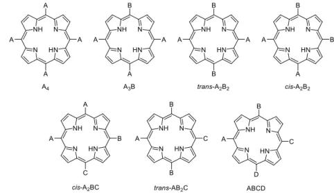
The properties of porphyrins can be modulated by chemical substitutions over the macrocycle which affect the planarity and thus the global electronic of the system. A non-substituted macrocycle is called porphin whereas the usual name porphyrin is dedicated to a macrocycle with substitutions. The substituents are generally observed on pyrroles (β positions) in natural porphyrins while most of the synthetic porphyrins are substituted on their methine bridges (meso positions). The variety of
meso-2
substituted porphyrins can be divided into seven categories abbreviated as A4, A3B, trans-A2B2,
cis-A2B2, cis-A2BC, trans-AB2C, ABCD depending on the nature and positions of the substituents (Fig.
I-3).
Fig. I-3 Representation of the seven categories of meso-substituted porphyrins
Moreover, the cavity of free-base porphyrins, with a size between 18 to 22 angstroms, is able to chelate most of metals from the periodic table and form metalloporphyrins (Fig. I-4). The coordination of a metal M is stabilized by the bonds with the four nitrogens within the macrocycle. Most of these metals are able to complete their coordination spheres with other relatively labile axial ligands (L). In addition to chemical substitutions, the presence and nature of the metal in the cavity also allows modulation of the optical and electronic properties of porphyrins with a visible effect on the UV-visible absorption spectra.
Fig. I-4 Coordination of a metal M in the cavity of a porphyrin macrocycle. Axial labile ligands L are susceptible to complete the sphere of coordination of the inserted metal.
3 Natural porphyrins
Porphyrin and its derivatives constitute a class of compounds particularly present in biological systems. Historically, the discovery of porphyrin is related to the first investigation in biology of chlorophyll. Chlorophyll is a central element in natural photosynthesis. Its structure is based on an analogue of porphyrin called chlorin in which two carbon atoms of a pyrrole ring are sp 3 hybridised; the macrocycle contains a Mg2+ cation (Fig. I-5).4 The chlorin core is also responsible for the intense
green colour of leaves.
Fig. I-5 Chemical structure of chlorophyll
In 1884, F. Verdeil suggested that the green pigment of leaves should have the same origin as the red colour of blood. Indeed, the origin of the apparent red colour of blood is due to a strong absorbance of haemoglobin, a metalloprotein known to ensure the function of transport of oxygen in most living organisms.5 Haemoglobin (Fig. I-6, a) is composed of four subunits, each containing an iron-porphyrin called heme. In biology, the term heme is used to describe the active centres of proteins based on iron-porphyrins. Nowadays, different types of hemes have been discovered and classified, the most abundant is the heme b (Fig. I-6, b).
Fig. I-6 a) 3D structure of haemoglobin; b) chemical structure of heme b.
a) b)
4 Synthetic strategies
Rothemund reported in 1935 the first method to synthesise symmetric meso-substituted porphyrins.6
This method consisted in the condensation of pyrrole and aldehyde in a closed tube with pyridine under an inert atmosphere. The tube was heated at different temperatures from 140°C to 220°C for 24h - 48h and led to porphyrins in 5-10% yields. However, the harsh conditions used for the synthesis limited the choice of starting materials and thus the development of this method. In 1964, an alternative method was reported by Adler and Longo who performed the condensation reaction in air with propionic acid instead of pyridine at reflux (Fig. I-7).7 This method usually yields 20% of meso-substituted tetra-aryl porphyrin in approximatively 30 min and is still applied nowadays for the gram scale preparation of porphyrins.
Fig. I-7 Synthesis of a 5,10,15,20-tetraphenylporphyrin (TPP) under the method developed by Adler and Longo.
By adapting the protocol of Adler and Longo, Little et al.8 developed a method called “mixed
aldehydes” to synthetise asymmetric meso-substituted porphyrins by adjusting the number of equivalents of different aldehydes. However, this method often leads to a complex mixture of isomers difficult to separate. In 1986, Lindsey developed a strategy to synthesise porphyrins giving up to 50% yield under mild conditions.9 In this method, the reaction was performed at room temperature (r.t) under an inert atmosphere of nitrogen (N2) or argon (Ar). A first step of polycondensation was
initiated by addition of catalytic amount of Lewis acid (TFA or BF3OEt2) to form the porphyrinogen.
In a second step, the porphyrinogen was oxidized with DDQ (2,3-dichloro-5,6-dicyano-1,4-benzoquinone) or p-chloranil (Fig. I-8) to afford the corresponding porphyrin.
5
To understand the strategy developed by Lindsey, the mechanism of the formation of porphyrin is displayed in Fig. I-9. The amount of the resulting porphyrin directly depends on the concentration of porphyrinogen formed by the cyclocondensation reaction which is in competition with the reaction of linear polymerisation. Therefore, to enhance the yield of the formation of porphyrin, it is necessary to increase the preliminary formation of porphyrinogen species. In the previous methods developed by Rothemund and Adler/Longo, the porphyrinogen was immediately oxidized after its formation by surrounding oxygen and the porphyrin product was thus kinetically formed. Knowingly that the formation of a macrocycle is thermodynamically favourable, the idea of Lindsey was to introduce an equilibrium in the reaction to increase the formation of thermodynamic species. Therefore, to avoid an irreversible oxidation of polymers, the condensation reaction is protected from oxygen and conducted under inert atmosphere. In a second time and only after reaching the equilibrium, the porphyrinogen is irreversibly transformed into porphyrin by oxidation.
Fig. I-9 Mechanism of formation of the tetrapyrrolic macrocycle of porphyrin.
In the early 1960’s, MacDonald described the synthesis of trans-A2B2 porphyrins with a protocol that
involved a first step of acid catalysed condensation between a dipyrromethane (containing the group A) and an aldehyde (containing the group B) that led to the formation of a porphodimethene intermediate. A second oxidation step afforded the corresponding A2B2 porphyrin (Fig. I-10).10
6
In addition to the formation of challenging A2B2 porphyrins, the authors demonstrated that
dipyrromethanes were species stable enough to be isolated as intermediates.
The major issue in this method was the possible rearrangement of substituents during the condensation reaction known as “scrambling” that could lead to a complex mixture of isomeric porphyrins.11 In 1998, the group of Lindsey reported optimal synthetic conditions to form trans-A2B2
porphyrin with a minimal scrambling as a function of concentration of acid and reactants.12 Last but not least, other methods exist for the formation of A3B porphyrins based on 3+1 condensation.13–15
Optical properties of porphyrins
The characteristic absorption spectrum (Fig. I-11, deep blue) of a free-base porphyrin is composed of an intense absorption band around 420 nm called “Soret” and less intense bands between 500-700 nm called “Q bands”. Four Q bands are expected for free-base porphyrins and two Q bands for metallated ones. The emission spectrum of a porphyrin exhibits two bands located between 650 nm and 720 nm (Fig. I-11, light blue).
Fig. I-11 Absorption (deep blue) and emission (light blue) spectra of a 5,10,15,20-tetraphenylporphyrin.16
NMR spectroscopy of porphyrins
The 1H NMR spectrum of a porphyrin displays three characteristic signals:
- β-pyrrolic protons are located around 8-9 ppm. The multiplicity and chemical shift of these signals depend on the symmetry of porphyrins and vary as a function of the substituents present at meso positions.
- Protons in meso position are located around 10 ppm.
- In free-base porphyrins, the protons of the nitrogen atoms in the cavity of the macrocycle are observed around -2 ppm with a broad signal characteristic of their labile nature.
The chemical shifts of the signals is due to an anisotropic magnetic cone in the macrocycle that strongly shields protons of the nitrogens in its cavity and deshields the protons in meso positions.17
0,00E+00 2,00E+06 4,00E+06 6,00E+06 8,00E+06 1,00E+07 1,20E+07 0,00E+00 5,00E+04 1,00E+05 1,50E+05 2,00E+05 2,50E+05 3,00E+05 3,50E+05 4,00E+05 350 400 450 500 550 600 650 700 750 800 Em is si o n (A U ) A b so rp ti o n , ε (L . m o l -1. c m -1) λ (nm) 480 500 520 540 560 580 600 620 640 660 680 λ (nm)
7
Optoelectronic and redox properties of porphyrins
As mentioned previously, a chelate effect due to the four nitrogens within the cavity of the macrocycle of porphyrins allows the formation of stable complexes with metals. Metallo-porphyrins exhibit redox properties that can be modulated by the nature of metals. The systems can be used as sensitizers to activate photo-induced oxidations like epoxidation,18–20 sulfoxidation,21–23 hydroxylation,24,25
oxidation of alcohols26,27 or to activate redox processes with oxygen.28,29 In addition to the nature of
metals, the variety of substitutions of porphyrins allows chemists to both control the symmetry and modulate the optoelectronic properties of porphyrins. Therefore, porphyrins constitute an appealing and convenient material for applications in energy conversion,30–33molecular sensing,34–36and non-linear optics.37–39 On the other hand, the development of materials with optical properties in Near Infra-Red region (NIR) is of great interest in biology. Particularly, the research in diagnosis and photodynamic therapy (PDT) requires the use of NIR dyes in excitation or in emission because of the relative transparency of biological tissues in the NIR region.40–43 In this context, a red-shift of the properties of porphyrins is attractive to promote NIR dyes. A red-shift of the optical properties of a material can be achieved by an extension of its electronic system that leads to a decrease of the HOMO-LUMO bandgap. Because porphyrins intrinsically strongly absorb in the visible region, the development of NIR dyes based on π-extended porphyrins has emerged as a hot topic of research.
π
-extended porphyrins
π-extended porphyrins can be seen as porphyrins with extended skeletons that are able to participate to the delocalization of electrons and exhibit structures, electronic and optical properties that are significantly different from those of porphyrins. The β-fusion of porphyrins with Polycyclic Aromatic Hydrocarbons (PAHs) is a popular method to form π-extended porphyrins with a red-shift of the optical absorption and emission.44 The general term of “fusion” describes the set of reactions able to connect molecular fragments to the porphyrin core by at least two bonds that prevent the free rotation between subunits, flatten the molecular assemblies and afford fully conjugated systems. The fusion of PAHs on porphyrins are achieved by cyclodehydrogenation or oxidative ring closure reactions that are not dissociated in the literature and often referred to a single term as Scholl reaction (Fig. I-12, b).45
meso-8
position of the porphyrin macrocycle and form a flat and conjugated π-extended porphyrin.
However, the cyclodehydrogenation reaction on PAH-porphyrins succeeds only under very specific conditions. Indeed, Yamane et al.46 reported in 2004 the fusion of pyrene on porphyrins and suggested that the fusion of PAHs should occur only when porphyrins were metallated with nickel and when PAHs contained ether or ester activating groups. Subsequently, the group of Osuka reported in 2006 the fusion of Ni-porphyrins substituted in meso-positions with azulene moieties containing esters. The quadruply azulene-fused porphyrins exhibited two major bands on the absorption spectrum at λ = 684 and 1136 nm.47 In 2011, the group of Anderson reported the fusion of four anthracenes on the core of a porphyrin and the resulting fused product exhibited strong absorption properties in the NIR region until 1417 nm (Fig. I-13).48 Recently, the groups of Müllen and Narita reported the fusion of hexabenzocoronene derivatives on Ni-porphyrins and the products of fusion exhibited intense absorption bands in NIR region up to 1176 nm.49
Fig. I-13 Absorption spectra and chemical structures of unfused- (left, grey) and fused- (right, black) [5,10,15,20-tetrakis(4,5-bis(mesityloxy)anthracen-9-yl)porphyrinato]Ni(II). Due to the fusion with the four anthracenes on the macrocycle, an important change of the optical properties was observed with a maximal
absorption band in NIR region at1417 nm.48
Unfortunately, the metalation of porphyrin with nickel causes a fast deactivation of the porphyrin excited states while the substitution with donor groups drastically limits tuning the periphery of the molecule. In 2012, the group of Thompson proposed a method of pyrolysis to activate the reaction of fusion of PAHs to meso-substituted Zn-porphyrins.50 This method does not require the presence of Ni in the porphyrin neither the presence of activating groups on PAHs and the efficiency of the method was demonstrated with porphyrins containing naphthalene, pyrene, perylene and coronene derivatives. The solubility and processibility of the fused compounds were conserved but mixtures of
9
syn/anti isomers were reported due to the asymmetry of the PAHs studied, as illustrated with the thermal fusion of [5,15-bis(pyren-1-yl)porphyrinato]Zn(II) (Fig. I-14).
Fig. I-14 Thermal activation of cyclodehydrogenation reaction of a [5,15-bis(pyren-1-yl)porphyrinato]Zn(II) leading to a mixture of isomers due to the free rotation of the pyrene moieties in the starting material.50
Porphyrin-based building blocks
Considering the robustness of the core of porphyrin and the easy access to a large variety of topologies, porphyrins are particularly suitable as building blocks for the formation of molecular materials. Indeed, the control of the number, positions and nature of the chemical substitutions with directional connecting groups allow the design of linear-, right-angled- or cross-shaped porphyrins. Drain and Lehn reported in 1994 a series of pyridylporphyrin building blocks for the formation of supramolecular dimers or square structures that self-assembled by coordination of trans or cis complexes of Pt(II) or Pd (II) (Fig. I-15).51
10
Fig. I-15 Supramolecular structures reported by Drain and Lehn. Pyridylporphyrin building blocks used to form different supramolecular architectures by coordination with trans-, cis- complexes of Pt(II) or Pd(II).51
The formations of supramolecular structures were monitored by UV-Visible spectroscopy; the spectra exhibited a red-shift of the Soret band and a change of the intensity of absorbance. Further evidence came from the chemical shifts on the 1H NMR spectra and the presence of unique compounds with Pt were confirmed by the observation of a single resonance on the 195Pt NMR spectra.
A large collection of examples incorporating porphyrin-based building blocks with variety of topologies can be found in the literature; these supramolecular architectures usually find applications in host-guest chemistry, artificial light-harvesting, catalysis and molecular photonics.52–58
Porphyrin-based polymers
In the context of porphyrin-based materials, porphyrins can be used as monomeric species to form polymers.59,60 One of the most impressive examples is the synthesis of a giant polymer with micro-meter length based on meso–meso linked porphyrins reported by the group of Osuka in 2005 (Fig.
I-16).61 This polymer containing up to 1024 monomers was formed by iterative synthesis via the coupling of zinc porphyrins in the presence of AgPF6.
Fig. I-16 Chemical structure of the giant polymer containing up to 1024 units of porphyrin reported by the group of Osuka.61
Porphyrins have been also widely used for the fabrication of 2D or 3D Metal Organic Frameworks (MOFs) (Fig. I-17).62,63 These networks were self-assembled by coordination of porphyrins with
metal complexes and the structure of the final assemblies were directly programmed by a careful choice of shape, size, positions and number of coordinated groups of the building blocks.
11
Fig. I-17 Examples of a) 2D; and b) 3D-MOFs structures.
π
-conjugated polymers of porphyrin
In the context of molecular electronics,64–67 π-conjugated polymers based on porphyrins have inspired scientists.68 Because the electronic interaction depends on the nature and the positions of the bridge between the moieties, several strategies to interconnect monomeric species and form π-conjugated polymers of porphyrins emerged.69,70 These strategies are summarized in three categories:
- Strategy A: monomeric porphyrins are connected with a single bond by using a π-conjugated bridge allowing the free rotation of macrocycles between meso-positions as, for example, with ethyne71–73 or ethene groups (Fig. I-18, a).74–76
- Strategy B: monomeric porphyrins are connected by fusing π-conjugated bridges at β-positions. For example, Crossley et al.77–79 used a polycondensation reaction between tetracyanophenyls and carbonyl groups at β-positions of porphyrins to form the fused polymer represented in Fig. I-18, b.
- Strategy C: monomeric porphyrins are connected through multiple bonds, by fusing porphyrin subunits at β,β-positions and meso,meso-positions. For example, the group of Osuka reported the structures of fully aromatic tapes of porphyrins consisted in flat 1D and 2D polymers of porphyrins as represented in Fig. I-18, c.80–82 The 1D extended polymer exhibited an
exceptional red-shifted absorption band up to 2800 nm.
a)
12
Fig. I-18 Illustration of the three main strategies applied to form fully π-conjugated polymers of porphyrin with corresponding examples from the literature. Porphyrin subunits can be connected by a) π-conjugated
bridge between meso-positions; b) β-bonds; c) three bonds connecting β-, and meso-positions.
It is worth mentioning that in solution, these strategies give a limited degree of polymerisation because of the decrease of solubility over the polymerisation process. Strategies of on-surface synthesis have been developed to overcome the limitation of solutions and achieve the formation of expanded assemblies of porphyrins. The assemblies are built-up from molecular precursors deposed on substrates (in situ in the chamber of a scanning tunnelling microscope) and the supramolecular assemblies are imaged via Scanning Tunneling Microscopy (STM).
Synthesis on surface
STM Operating principle
Scanning Tunneling Microscopy (STM) is an analytical tool that allows imaging of the surfaces and adsorbed species with atomic resolution. The simplified operating concept of a scanning tunneling microscope shown in Fig. I-19, is based on a dependence of the tunnelling current with the distance separating a conductive tip ending with a single atom (probe) and a conductive surface (sample).83,84 The sensitivity of the STM technique is derived from the exponential dependence of the tunnelling current that makes possible the detection of small variations of distance between the probe and the
13
surface. To keep a constant value of the tunnelling current while scanning horizontally the plane of a surface with the tip (x, y positions), the position of the probe along the z axis has to vary as a function of the morphology of the surface. Consequently, the morphology of a surface can be imaged by combining the data positions on the plane (scanning surface along x, y axes) and out of the plane (along z). An example of an image of the topographic scan of a surface of graphite by STM is shown in Fig. I-19.
Fig. I-19 Illustration of the operating principle of a STM.
STM can operate either in solution at ambient pressure and room temperature (r.t) or under ultra-high vacuum (UHV) conditions. STM at the solid-liquid interface simplifies the maintenance and the preparation of samples but the substrates are exposed to the surrounding environment, which can modify the surface of sensitive substrates. In contrast, STM under UHV conditions drastically limits the access to samples and usually implies the preparation of the sample in-situ. However, oxygen-sensitive surfaces are preserved from the external environment that allows the use of catalytic substrates and chemical reactions required to form covalent assemblies on surface. Therefore, STM under UHV conditions have been widely used as a powerful analytical tool to explore the structures of covalent nanomaterials prepared by “on-surface” synthesis.85–87
Covalent assemblies of porphyrins on surface
Although few examples were reported in the literature in 90s,88,89 the “on-surface” synthesis have
truly emerged as a promising strategy for the bottom-up fabrication of well-defined molecular assemblies since 2007. Grill et al.90 reported the formation of dimers, linear chains and 2D networks of porphyrins from the polymerisation of variety of para-substituted bromotetraphenylporphyrins via surface-assisted Ullmann coupling on Au (111) (Fig. I-20). Although STM was used as an analytical
14
tool to visualize the assemblies on the surface, this technique probes low-energy electronic states and cannot be related to the bonding structures. Therefore, STM images were supported with theoretical calculations to provide a reliable interpretation of the structures.
Fig. I-20 a) Chemical structures of the designed building blocks based on para-substituted tetraphenylporphyrins with bromines; b) STM images of the corresponding controlled assemblies after
on-surface polymerisation of the precursors leading to dimers, linear chains and 2D networks; c) chemical structures of the corresponding nanostructures.90
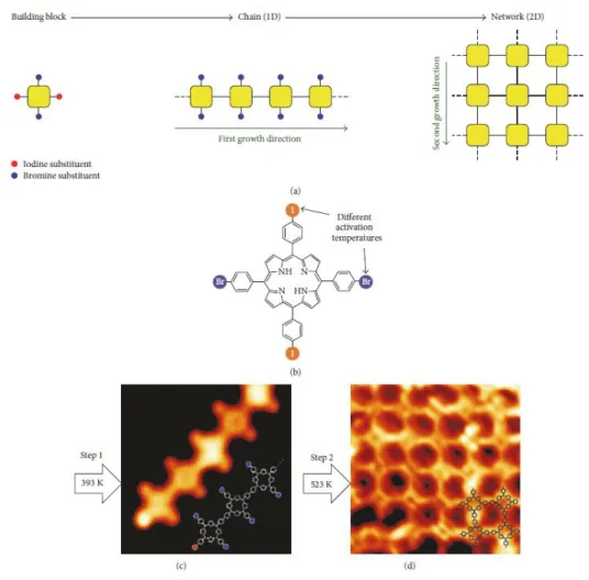
Hierarchical strategies by means of control of the order of activation of surface-assisted reactions have been investigated by Lafferentz et al.91 with the deposition of 5,15-bis(4-bromophenyl)-10,20-bis(4-iodophenyl)porphyrins on Au (111). Annealing the surface at T1 (393K) induced a first polymerisation with the activation of iodines that led to the formation of linear chains. Additional annealing the surface at T2 (523K) induced lateral polymerisation between chains by activation of bromines that led to the desired formation of networks of porphyrins (Fig. I-21).92 This work demonstrated the difference of temperature of activation of the Ullmann coupling depending on the nature of the halogens that allowed the selective control of the direction of growth and the structure of the nanomaterial on the surface.
On-surface synthesis c BrTPP trans-Br2TPP Br4TPP a) b) c)
15
Fig. I-21 a) Illustration the hierarchical Ullmann-coupling strategy. b) Chemical structure of 5,15-bis(4-bromophenyl)-10,20-bis(4-iodophenyl)porphyrin and STM images of c) the linear chains formed by iodines
activation after annealing the surface at T1 (393K); d) the network of porphyrin afforded by bromines activation after annealing the surface at T2 (323K).91,92
As an alternative to the Ullmann-coupling, Sonogashira-type93and Heck-type94 coupling reactions have also been reported with porphyrins on a surface. In addition, Wiengarten et al.95 reported the
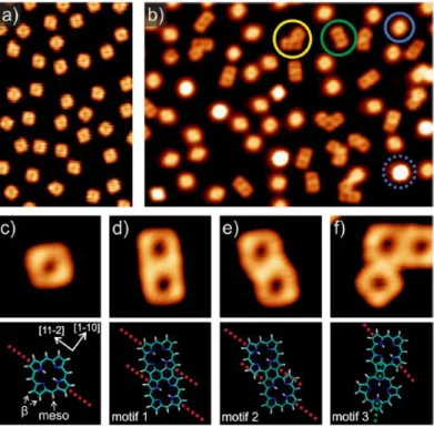
polymerisation of porphine via surface-assisted dehydrogenative homocoupling via direct CH activation. From STM, Near-edge X-ray Absorption Fine Structure (NEXAFS) and theoretical calculations, three distinct motifs of coupling were comprehensively distinguished (Fig. I-22). Consequently, the control of the direction of polymerisation without the use of halogens on precursors seemed to be more difficult and led to the formation of various kinked structures.96–98
16
Fig. I-22 STM images on Ag (111) of a) free-base porphines and; b) products on surface after annealing at 573K with presence of monomers (blue), dimers (green), trimers (yellow) and porphines interacting with Ag
adatoms (dashed blue circle); c) single porphine monomer with theoretical model; (d−f) Three motifs of coupling identified with corresponding structural models.95
Beyond the coupling reactions, the first suspicions of surface-assisted cyclodehydrogenation were reported by Di Santo et al.99 in 2011 and Xiao et al.100 in 2012 from the study of the insertion of
metal atoms from the surface into the cavity of a free-base TPP. Chemical and structural changes were tracked by XPS and STM and suggested the presence of cyclodehydrogenated species, but no structures of fused species were proposed. Further insights on the structures of fused products of TPP were provided by Wiengarten et al.101 on Ag (111). After annealing the surface at 520K and cooling to 6K, structures of partially fused products (spots with bright lobes due to upstanding configuration of phenyl rings, Fig. I-23, a-d) and isomers of tetrafused TPP (flat spots, Fig. I-23, A-D) were identified in STM images in agreement with theoretical studies. The authors demonstrated that the cyclodehydrogenation of the phenyl moieties of TPP could be achieved on the surface and suggested that the reaction occurred in multiple steps.
17
Fig. I-23 a-d) STM images on Ag (111) and e-h) theoretical models of a free-base TPP with its corresponding fused products from the dehydrogenation of one, two, three phenyls respectively; A-D) STM
images and corresponding chemical structures of isomers of tetrafused phenyls of TPP.
Although the fusion of phenylporphyrins can be found in the literature (see I. 1.3),101–104 no studies related to the on-surface cyclodehydrogenation of PAHs to porphyrins have been reported so far. However, the surface-assisted cyclodehydrogenation of PAH-porphyrins would constitute a convenient strategy to generate π-extended porphyrins by a method other than the Scholl reaction developed in solution. Porphyrins have been also investigated on surface to modify the properties of graphene. The group of Barth reported the functionalization of the edges of graphene with porphines105 and the group of Pascual reported a hierarchical strategy to form hybrid systems based on the combination of TPP and graphene nanoribbons (GNRs) (Fig. I-24, b).106 The second example of incorporation of porphyrins into GNRs was reported by Perkins and Fischer via solution-mediated synthesis to investigate the original optical properties of the material (Fig. I-24, a).107
18
Fig. I-24 Chemical structures of a) the hybrid system based on Fe-TPP-GNRs with the corresponding nc-STM image and; b) graphene incorporating a porphyrin molecule.106,107
Finally, the chemical structures of porphyrin assemblies synthetised in solution or on a surface exhibit important structural similarities with graphene structures. Particularly, the tape-like polymers of porphyrins reported by the group of Osuka in solution (Fig. I-18, c) strongly resemble the structure of GNRs108 and can be regarded as nitrogen-doped GNRs. In the next section, I will introduce graphene and graphene related-materials like GNRs and I will show that the control of doping of graphene with nitrogen is a hot topic of research that aims to control the electronic properties. In this context, the contribution of porphyrins with a controlled nitrogen content is an attractive subject of research.
b) a)
19
Graphene and graphene related nanostructures
Generalities
Graphene is an atomic thick monolayer of carbon sp2 arranged in a 2D honeycomb lattice (Fig. I-25,
a). This atomic plane derives from the structure of graphite in which thousands of sheets of graphene are sustained by strong π-stacking interactions (Fig. I-25, b).
Fig. I-25 Representation of a) monolayer of graphene; b) crystallographic structure of graphite
Although it was postulated for decades and theoretically expected to be unstable, the existence of graphene was experimentally demonstrated in 2004 by Geim and Novoselov, who obtained the Nobel Prize in Physics in 2010 for the isolation and their experiments on a single layer of graphene.109,110
The preparation of high quality graphene was achieved by a simple method based on the mechanical exfoliation of a crystal of graphite with scotch tape.111
Fig. I-26 Illustration of mechanical exfoliation of graphite. a) Adhesive tape is pressed against a surface of graphite; b) A few layers of graphene are peeled off and attached on the tape; c) the tape with layers of graphene is pressed against the surface of a new substrate; d) by peeling off, only layers at the bottom are
deposed on the surface of the substrate.111
The simplicity of this method has inspired the community of scientists to investigate the properties of graphene and a new topic of research for graphene and 2D materials emerged.112–115 Graphene
shows a high electronic mobility of about 200 000 cm2 V-1 s-1 for suspending graphene116 (150 times
20
than copper),117,118 and a quantum Hall effect even at room temperature.119–121 Regarding its mechanical properties, graphene is very robust and possesses a Young’s modulus of ~ 1TPa and a tensile strength of ~ 130 GPa.122 In addition, graphene is transparent and flexible, which is particularly suitable for flexible electronic applications.123,124
Although the modulation of its electronic properties is sensitive to its environment,125,126 graphene became a very promising material for a wide range of applications, from electronics,127–130 energy conversion and storage,131–133 catalysis134,135 and sensing136,137 to photonics.138–140
Nevertheless, the valence and the conduction bands of graphene are cone-shaped and both meet at the Dirac point where the density of state is zero, meaning that graphene is a semi-metal with an electronic bandgap equal to zero (Fig. I-27).112 Therefore, the current in a graphene-based transistor cannot be switched off properly, which drastically hinders the integration of graphene in Field Effect Transistor (FET) devices.141 In order to broaden the range of applications in semi-conductors, a great challenge in fundamental research is to open a bandgap in the electronic structure of graphene.
Fig. I-27 Partial representation of the band structure of graphene with an enlargement of the energy bands close to one of the Dirac points.112
Bandgap opening
Theoretical and experimental studies suggested that a sizeable bandgap can be opened in graphene by nanostructuration. The method that has been widely reported in the literature, consists in the structural confinement of graphene and the fabrication of nanostructures with at least one dimension at the nanoscale.142,143
Nanostructures of graphene
It is well known that matter reduced to its nanometer scale exhibits completely different properties than the bulk material. For example, CdS or CdSe Quantum Dots (QD) possess semi-conducting and high luminescence properties that only exist at the nanoscale and can be modulated by the size and the shape of the particles.144,145 Likewise, by reducing the size of graphene down to the nanoscale, an
21
important modification of the electronic properties is expected and a sizeable bandgap can be opened.146
The nanoscale reduction of two dimensions of graphene leads to Graphene Quantum Dots (GQDs) with optical bandgaps that depend on the size and the shape of the particles (Fig. I-28, a).147 GQDs are potentially interesting for biology because of the chemical inertness of carbon materials, their generally low cytotoxicity and high biocompatibility.148–151
Fig. I-28. Representation of the structural confinement of graphene to afford a) nanoparticles of graphene called GQDs; b) stripes of graphene called GNRs; and c) porous sheets of graphene with regularly patterned
nanoholes called GNMs. All of these nanostructures of graphene exhibit opened bandgaps.
The nanoscale reduction of one dimension of graphene leads to Graphene NanoRibbons (GNRs) that structurally consist in stripes of graphene with nanometer widths that govern the value of the bandgaps (Fig. I-28, b).152–155 For example, armchair-type GNRs (A-GNR)156 are predicted to exhibit semiconducting behaviours, whereas zig-zag types (Z-GNRs)157 are predicted to exhibit interesting
magnetic properties because of the strongly localized charge density of the edge state at the zigzag sites (Fig. I-29).
22
As an alternative to reducing dimensionality, Graphene NanoMeshes (GNMs) are porous graphene sheets with regularly patterned nano-holes (Fig. I-28, c). It was predicted in 2008 that GNMs should exhibit bandgaps158 and this was experimentally confirmed in 2010.159 Several structural parameters have to be precisely controlled to tailor the electronic properties of GNMs with accuracy.160–162 As illustrated in Fig. I-30, these parameters are intrinsically due to the control of the patterned nanoholes like the neck, the periodicity, the form, the size, the variation of the edge states that can be even multiple in a single hole etc.
Fig. I-30 Illustration of the range of structural parameters that affect the electronic properties of GNMs.
Two methods can be used to produce gaped graphene materials:
The first one is the top-down approach, it is based on a strategy that physically carves the desired structure of nanoscopic materials from the bulk graphene or graphite.
The second is the bottom-up approach, based on the controlled assembly of small entities used as building blocks for the creation of larger and structurally well-defined nanomaterials. These two approach are described in the following sections.
Top-down approach
Top-down preparation of Graphene Quantum Dots
The principal method for the top-down preparation of GQDs is based on a chemical ablation of graphite (Fig. I-31).163 This sequential method requires a first step of oxidation of graphite by the method of Hummers164 to form graphene oxide. The second step consists in the oxidation and sonication of the graphene oxide flakes to break them into nanometer pieces. A last step of chemical reduction affords GQDs. c neck periodicity Holes diameter
Zig Zag type edges Armchair type edges
Holes nanoforms
23
Fig. I-31 Chemical ablation method commonly used for the top-down preparation of GQDs from graphite.163
Although this method allows a mass production, the low control of the size, the shape, the edges and the oxidative states of the resulting GQDs constitute important limitations that render impossible a control of the opto-electronic properties of the nanomaterial. Other top-down methods have been reported in the literature for the fabrication of GQDs including the chemical or electrochemical oxidation/exfoliation,165 the solvothermal techniques166 or the oxygen plasma treatments.167 All of
these methods lead to a distribution of particle sizes with broad optical absorption or emission from the visible to the NIR region.
Top-down preparation of Graphene Nanoribbons
The first method of preparation of GNRs was described from expanded graphite. GNRs were afforded by a rapid thermal annealing followed by dispersion using poly(m-phenylenevinylene-co-2,5-dioctoxy-p-phenylenevinylene) (PmPV) in 1,2-dichloroethane (DCE).168 The resulting GNRs were
obtained with a poor yield and a broad width distribution (from less than 10 nm to 100 nm). Subsequently, alternative methods based on the etching of carbon nanotubes (CNTs) were developed.169,170 In the first method, multi-wall carbon nanotubes (MWCNTs) were deposited on a silicon substrate and embedded in poly(methyl methacrylate) (PMMA). The PMMA-MWCNT film was exposed to an argon plasma to selectively etch the upper part of the tubes. Depending on the etching time, single layer GNRs could be isolated with widths from 10 to 20 nm (Fig. I-32, a).169 The second method was based on chemical unzipping to produce well-defined GNRs (Fig. I-32, b) and the resulting GNRs exhibited widths from 20 to 100 nm with a yield of up to 100% depending on the oxidation conditions.170
24
Fig. I-32 Top-down methods for the preparation of GNRs by a) Argon plasma etching from MWCNTs; and b) Unzipping of MWCNTs by chemical oxidation.
Top-down preparation of Graphene Nanomeshes
The main strategy to prepare GNMs is to drill regular and periodic holes in a graphene sheet. The first attempts for the fabrication of GNMs were based on the electron and ion-beam lithography techniques.171,172 The structural parameters like the position, shape and size of the pores were controlled by the positioning and the movement of the beam. The technique was time consuming and not appropriated for the conception of regularly patterned networks of holes.
From 2010, a series of methods based on nanolithography with etching techniques have been developed.159,173–175 A famous example of nanolithography through a template-mask based on co-polymer was reported by Bai et al.159 (Fig. I-33). A graphene sheet was covered with a thin layer of evaporated SiOx and a thin film of polystyrene/polymethylmethacryalte (PS/PMMA) block
copolymer. The copolymer was annealed and developed to selectively remove PMMA leaving a porous PS template. Fluoride-based reactive ion etching (RIE) was used to etch the exposed SiOx and
oxygen plasma was used to remove the remaining PS film that formed the holes in graphene. Finally, the SiOx layer was removed with HF treatment leading to the desired graphene nanomesh.159
Although a bandgap of about 0.1 eV was determined by electrical transport measurements, an atomically control of structural parameters like the periodicity, the size, the form and the multi-edges states of holes could not be attained with the method, which did not allow a predictable control of the bandgaps of GNMs.
25
Fig. I-33 Nanolitography method with etching process for the preparation of GNMs. A graphene sheet was covered with a thin layer of evaporated SiOx and a thin film of polystyrene/polymethylmethacryalte
(PS/PMMA) block copolymer. PMMA was selectively removed by annealing leaving a porous PS template. Fluoride-based reactive ion etching (RIE) removed the exposed SiOx layer and oxygen plasma was used to
remove the remaining PS film and form the holes in graphene. Finally, the SiOx layer was removed with HF
treatment leading to the desired graphene nanomesh.159
Although other methods based on local catalytic hydrogenation of carbon by Cu nanoparticles176 or local photodegradation of graphene oxide sheets with ZnO nanorods followed by reduction177 have also been reported, these methods do not offer a better control of structures of GNMs than the nanolithography techniques described above.
To sum-up, the top-down approaches allow the formation of large amount of materials but the lack of control of structures represents an important drawback that has to be tackled to tailor precisely the bandgap of nanomaterials.
Bottom-up approach
Applying the bottom-up approach for the fabrication of GQDs, GNRs and GNMs potentially allows the control at the atomic level of both the morphology (edges state, defects, size…) and the chemical composition of materials. In particular, this method permits control of doping parameters, such as ratio, type and position of dopants. Because the structure of graphene can be seen as multiple fused benzene rings forming a flat and electronically delocalized polymer, the bottom-up approach is usually decomposed into two-steps. First, the formation of a 0D-, 1D- or 2D- species that constitutes the molecular skeleton of the final structure and a second step of cyclodehydrogenation that induces
26
the aromatization of the system leading to the final conjugated structure. These two-steps can be achieved in solution or on-surface.
Bottom-up preparation of Graphene Quantum Dots
A general procedure for the synthesis of GQDs is illustrated in Fig. I-34 by the typical examples of synthesis in solution of “supernapthalene and supertriphenylene“ developed by the group of K. Mullen in the 199s.178 Polyphenylene precursors were formed in the first step by a Diels-Alder
reaction and then oxidised in a second step by the Scholl reaction to afford the corresponding GQDs.
Fig. I-34 General procedure for the synthesis of GQDs with the example of synthesis of “supernapthalene” and “supertriphenylene”.178
Since then, several structures with different shapes were synthesised and investigated for their electronic, absorption and photoluminescence properties.179–183 The biggest structure synthetised so far contained 474 carbons; unfortunately, it was not possible to fully dehydrogenate the compound via the Scholl reaction and only propeller-shaped molecules were obtained.184 In order to improve the solubility of GQDs, the periphery of the molecules can be functionnalized with alkyl chains185,186 or with chlorine atoms.187
Despite the large variety of GQDs synthesised so far, examples of nitrogen-doped structures remain limited because the cyclodehydrogenation of molecules containing pyridyl moieties cannot be achieved in solution.188,189 The difference of activation between pyridyl groups and benzene-like rings can be related to an electronic deactivation of C–H bonds of the 4-pyridyl groups and a non-stabilization of radicals required to achieve the cyclodehydrogenative coupling at specific positions.45 As an alternative to solution-based processes, GQDs can be prepared in situ on surfaces by deposition of precursors on catalytic substrates followed by cyclodehydrogenation, as demonstrated by Fasel and collaborators in 2010 on a triangular PAH.190,191
27
Using a similar strategy, Pinardi et al.189 succeeded in the complete cyclodehydrogenation of pyridyl-disubstituted dibenzo-helicene on Pt (111) that could not be achieved in solution. The authors demonstrated the difference of energy required to fuse benzene- and azabenzene rings by the sequential activation of the reactions of cyclodehydrogenation on surface at 450K and 650K (Fig.
I-35). Although most GQDs are synthetised in solution, the last example demonstrated the potential
of “on-surface” synthesis that can be applied as an alternative method for the preparation of GQDs.
Fig. I-35 Surface-assisted cyclodehydrogenation on a pyridyl-disubstituted dibenzo-helicene.189
Bottom-up preparation of Graphene Nanoribbons
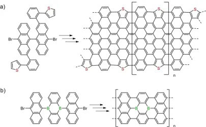
The fabrication of GNRs was first achieved in solution using different synthetic strategies mainly based on Diels-Alder,192–194 Suzuki-Miyaura195–197 or Yamamoto coupling reactions,198–200 followed by cyclodehydrogenation (Fig. I-36). These strategies led to a variety of well-defined GNRs with atomically precise edges, lateral functionalities or structural features such as gulf-type edges (Fig.
I-36, a),193 armchair-edges (Fig. I-36, b),195 chevron-type structures (Fig. I-36, c).199
Fig. I-36 Main synthetic strategies developed in solution for the synthesis of GNRs via a) AB type Diels-Alder polymerisation;193 b) A
28
Beyond the modifications of morphology like width and edges, bandgaps of GNRs can be also modulated by doping with heteroelements. The bottom-up approach allows the control of doping parameters like the positions of dopants and the doping ratio in the structures. For example, Vo et al.201 reported the formation of a nitrogen-doped c-GNR from 5-(6,11-dibromo-1,3,4-triphenyltriphenylen-2-yl)pyrimidine monomer (Fig. I-37). Considering the partial cyclodehydrogenation reported with the example of pyridyl-disubstituted dibenzo-helicene in solution (Fig. I-35), we can wonder if the nitrogen-doped c-GNR reported in this work was fully conjugated. Only the resolution of its bonding structure with non-contact STM202,203 would definitely prove the authenticity of the fully conjugated nitrogen-doped c-GNR reported.
Fig. I-37 Example of c-GNR doped with nitrogens. By the use of a bottom-up approach , doping parameters like positions of dopants and doping ratio are perfectly controlled and defined.201
In 2010, Fasel and Müllen developed a surface-assisted protocol for the formation of A-GNR and c-GNR.108 The protocol depends on a hierarchical strategy based on a first step of dehalogenative coupling at T1 (around 200°C) and a second step of cyclodehydrogenation to afford the corresponding
GNR at T2 (around 400°C).
For the last nine years, inspired by the work of Müllen and Fasel, many GNR structures and GNRs containing heterojunctions have been reported and studied in order to understand the impact of the structural parameters and the role of doping on the optical and electronic properties of ribbons.204