Publisher’s version / Version de l'éditeur:
Vous avez des questions? Nous pouvons vous aider. Pour communiquer directement avec un auteur, consultez la première page de la revue dans laquelle son article a été publié afin de trouver ses coordonnées. Si vous n’arrivez pas à les repérer, communiquez avec nous à PublicationsArchive-ArchivesPublications@nrc-cnrc.gc.ca.
Questions? Contact the NRC Publications Archive team at
PublicationsArchive-ArchivesPublications@nrc-cnrc.gc.ca. If you wish to email the authors directly, please see the first page of the publication for their contact information.
https://publications-cnrc.canada.ca/fra/droits
L’accès à ce site Web et l’utilisation de son contenu sont assujettis aux conditions présentées dans le site LISEZ CES CONDITIONS ATTENTIVEMENT AVANT D’UTILISER CE SITE WEB.
Report (National Research Council of Canada. Division of Building Research), 1951-11-01
READ THESE TERMS AND CONDITIONS CAREFULLY BEFORE USING THIS WEBSITE.
https://nrc-publications.canada.ca/eng/copyright
NRC Publications Archive Record / Notice des Archives des publications du CNRC : https://nrc-publications.canada.ca/eng/view/object/?id=fe37f00d-98ec-4f96-919f-761a55427608 https://publications-cnrc.canada.ca/fra/voir/objet/?id=fe37f00d-98ec-4f96-919f-761a55427608
Archives des publications du CNRC
For the publisher’s version, please access the DOI link below./ Pour consulter la version de l’éditeur, utilisez le lien DOI ci-dessous.
https://doi.org/10.4224/20386709
Access and use of this website and the material on it are subject to the Terms and Conditions set forth at
Report on an Investigation of a Full Scale Wall Panel Insulated with
Alfol Type II Improved Blanket
MMMMMMMMNセMMMMMMMMM .--- --. . -'-'--'.-.-.._---.-
-_
__..-._---NATIONAL RESEARCH COUNCIL
CANADA
REPORT ON AN INVESTIGATION OF A FULL SCALE WALL PANEL
INSULATED WITH ALFOL TYPE II IMPROVED
blaセスゥャゥtby
G.
O.Handegord
J.NAlvzeD
November, 1951
(PREPARED FOR CENTRAL MORTGAGE AND HOUSING CORPORATION)
(Not for Publication)
-...-
I
!
Research Report No.
5
of the
Division of BUilding Research
Ottawa
l I II
_
.._-_.
MMセ
The Division of Building Research has been privileged to work closely with Central Mortgage and Housing Corporaticn9
since the start of its キッイォセ in connection with certain problems which have arisen in the use of reflective types of insulation in houses built by the Corporation or under its authorityo
Correspondinglyv the Division has been privileged to keep in close touch with the manufacturers of this type of insulation in Canada9 and in particular with Mro Henry Wiser
of Aluminum Insulation Limitedo
wィ・ョセ therefore9 the latter Company submitted to the
Corporation a new type of Alfol blanket for consideration9 the
Division was glad to agree to the request of the Corporation that it should test this new product in its Thermal Laboratory at its Prairie Regional Station in Saskatoono
This report records the results of the tests on this material which were most carefully carried out by Mro Go 00 Po
Handegord and his associates with the advice of Dro No Bo Hutcheon$' Consultant to the Divisiono
Results of some corresponding tests on ordinary frame wall construction have been reported in a paper by Mro Handegord and Dro Hutcheon which is being presented to the Annual Meeting of the American Society of Heating and Ventilating Engineers to be held at Sto lッオゥウセ MOo 9 in JanuarY9
19520
Considerationof this paper will make the results of the tests herein reported more significanto
Ottawa,
November9
1951
Ro Fa Legget, Directoro
Report on An Investigation of a Full Scale Wall Panel Insulated with Alfol Type II Improved Blanket
by
Go 00 Handegord
Introduction
During the w inter of 1948=49 investigations conducted by the University of Saskatchewan and the Division of Building Research indic ated certain unde sirable fe ature s of two type s of Alfol
insulation (1)0 These features were associatedp to a large extentp
with the physical features of the insulation in the vicinity of framing members, which resulted in variations in inside surface temperature and increased heat flow through studdingo
In 1949 an investigation of other types and methods of installation of Alfol was conducted at Pennsylvania State College (2) sponsored by the Division of BUilding Researcho This study compared the performance of Alfol-insulated walls with walls insulated with batt insulations at various outside temperatureso
As a result of these investigations p the manufacturers of Alfol developed a new form of the insulation designed to eliminate the defects which had been discoveredo This new type of Alfolp
termed Alfol Type II Improved Blanketp was submitted to the Prairie
Regional Station of the Division of Building Research for testingo This report deals with the results of the tests conducted using the steady-state wall=panel test apparatus 0
Description of Test Panel
A full-scale test panel 8 feet in height and
5
standard stud spaces wide was employedo The panel consisted of 6= by セセゥョ」ィbevel cedar sidings> Scutan "rredium" sheathing p ape r , 10= by l=inch spruce shiplap she athing p 2= by Tセゥョ」ィ studdingp and 3/8=inch
plasterboard interior finish o Sheathing and siding were secured with ャセ]ゥョ」ィ wood screws and the siding painted with one prime coat
and two finish coats of white exterior house painto Alfol Type II Improved Blanket insulation was installed in all
5
stud spaces in accordance with the manufacturer's directions (letters dated July 27 and August lOp 1951) and the interior plasterboard secured with 3/4-ino #10 (steel) wood screwso A 1= by 3=inch edge strip was fastened around the perimeter of the panel with wood screws into the edge framing membersp as shown in Figc 19 to bear against the rubbergasket surrounding the test openingo The space between the panel and surrounding test opening was packed with wood=fiber insulation o
Details of the installation of Alfol Type II Improved Blanket are given in Appendix A of this Reporto
Test Procedure
With the ー。セ・ャ in position, the cold=side air temperature was reduced to =40oFo in 20 hourss with warm=side air conditions being maintained at 70oFo and 40 per cent relative humidity0 The panel was subjected to these conditions for five dayso On the
third day, temperatures throughout the wall were measured and rates of heat flow into the area over the stud to the left of the centre stud space and into the centre of the centre stud space were
measured at various ィ・ゥァィエウセ using two Tセ] by Tセ]ゥョ」ィ heatmeterso The heatmeter eomofo at each location was recorded for a period of
セ to 1 hour and the mean values calculated o A hair type hygrograph was used to record humidities in the warm rooms and this record was checked periodically with a sensitive electrical resistance type hygrometero
After five days' operation at =40 oFo, the cold-side temperature was increased to =20oFo s and the panel SUbjected to this condition for 14 dayso On the third days temperature and heatmeter measurements were made as beforeo At the end of the 14 days, the plasterboard was removed and the interior of the panel
・ク。セゥョ・、 for condensationo
During the entire test periods air flow conditions on the warm and cold sides of the panel were maintained constant at approximately 250 fopomo and 500 fopomo respectivelyo Air
temperatures in the warm room were held to within
=
セッfッ and in the c8ld room to within セ lOFoTe st Re suI ts
The test results are presented graphically in Figso 2 and
3
for cold room temperatures of =40 oFo and =20oFo respectivelyo Temperatures measured at various planes within the wall and the corresponding rates of heat flow into the wall have been plotted against height0 In both figures the following numbering system for the temperature curves has been employedoCurve No o 1 2
3
4 56
7 LocationWarm side air = 1 inch from panel surface0 Inside surface of plasterboard = centre of
centre stud spaceo
Outside surface of plasterboard セ centre of centre stud spaceo
Inside surface of plasterboard - centre of stud to right of centre stud spaceo
Centre of air sp ace 0
Inside surface of sheathing0
=
3
=At the end of the =40 oFo run9 some condensation was noticed
on the inside surface of the wall near the bottomo This surface condensation extended fr9m
6
to9
inches above the bottom of the wall at areas over studding and from 2 to 3 inches at areas betweenstuddingu During the =200F o run
i surface condensation occurred
only over studding9 extending some 2 to 4 inches above the bottom of
the wa l I ,
At the completion of the =200Fo run, condensation on the heads of the 3/4=inch screws holding the plasterboard in place was noticed9 and rust had formed on all heads up to the 4=foot levelo
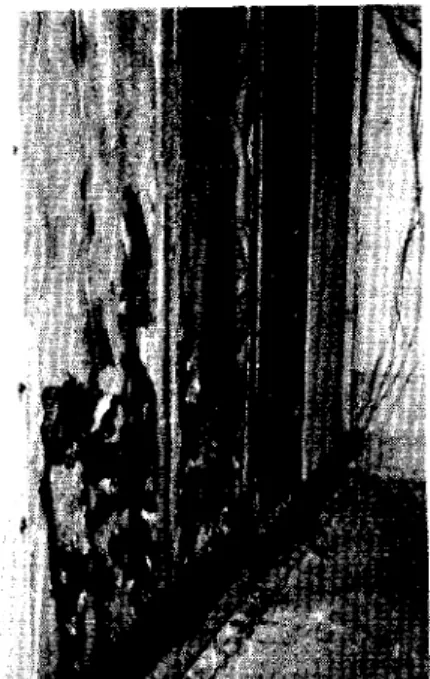
Removal of the plasterboard revealed that condensation had occurred on the kraft paper backing of the insulation up to the 2=foot levelo In some spots the kraft paper was thoroughly soaked (Figo 6)0
Examination of the interior of the wall at the completion of the -200Fo run showed considerable frost on the interior surface of the sheathing9 concentrated largely between
5
and6
feet fromthe bottom of the wall (Figo
7)0
This frost formation was approxi= mately t=inch thick in placeso An attempt was made to remove this frost and a total of 110 grams was collected from the centre stud spaceo Examination of the insulation in this stud space revealed that frost had also accumulated between the two outer foil curtains and approximate measurements indicated that at least96
grams had been presento Although similar condensation on the sheathing had occurred in the two adjacent stud spacesj it was not determined whether frost had formed between foil cur-t af.ns ,Appendix B of this Report outlines the effect of this condensation on overall transmittance0
Discussion of Test Results
The test results presented in Figso 2 and 3 represent values obtained under a particular set of conditions and for a particular panel constructiono Previous to this investigation a study of the performance of walls insulated with 2=inch batt
insulation had been c ompLet e d, using the same basic pane 10 Al though co Ld-z-oom air temperatures were different in these tests and lower humidities were maintained in the warm room9 test conditions were
sufficiently similar to provide some basis for comparison of thermal propertieso The results of. these tests are therefore included in this report as Figso 4 and
50
Because of the' differences in cold=room temperature between the various tests9 Table I has been prepared to facilitate
comparisono To correct for these differencesj apparent transmit-tance values were calculated from the curves in Figso 21 39 49 and
59
by dividing the heat flow rates at different heights by the average inside to outside temperature difference and mUltiplying by a factor of 1025 (as recommended in Reference(2))0
Theresultant values have been listed in the table together with the corresponding average transmittanceo
Insofar as heat flow into the centre of the stud space is concernedg Table I indicates that similar characteristics were
exhibited by the wall with Alfol insulation and the wall in which mineral wool batt insulation was installed against the she.at.hLng , Essentially the same increase in apparent transmittance occurred
at the bottom of these walls and this feature is reflected by the inside surface temperature curves in Figso Rセ
3))
and 40 Theeffects of compressing the Alfol blanket between the plasterboard and the top plate are indicated by the surface temperature gradient in this regiono This feature probably contributed to lowering of the surface temperature at the bottom of the wallo
The rate of he at flow into the s tu ddi ng was me asur-e d only in the case of the aャヲッャセLゥョウオャ。エ・、 wallo An approximate value of overall transmittance may be calculated from the data presented in Table I by assuming that the area of increased heat flow into
the stud is 15 per cent of the totalo On this basis9 the approximate
overall transmittance of the Alfolc"insulated wall isg For a temperature difference of 8905°Fo
U (overall) セ (0085 x 00091)
+
(0015 x 00195) セ00107 Btu!ft 2!hr!OFo· For a temperature difference of 111oOoFo
U
(overall) セ(0085
x 00092) + (0015 x 00190) セ 200107 Btu!ft !hr!OFo Although no measurements of heat flow into the stUdding were made on the 「。エエセゥョウオャ。エ・、 walls9 the lowering of surface
temperature in this area provides a qualitative basis for comparisono Table II has been prepared to facilitate such comparisono In this t。「ャ・セ the temperature differences between the surface over the stUd セ、 the surface over the stud space at different locations
have been listed)) together with the average of these valueso Judging from the data presented)) no appreciable increase in heat flow into the studding would be expected in the case where 2=inch mineral wool batt insulation is placed against the sheathingo The overall エイ。ョウュゥエエ。ョ」セ value for such, a wall would probably be approximately 00097 Btu!ft !hr!OFo In a wall in which the 2=inch batt insulation is placed immediately beneath the plasterboard)) the effect of
stUdding would be to increase the transmittance but not to as great an extent as in the Alfol-insulated wallo On the basis of results obtaine d from the Te st Hut pro je ct at S askat oon , the overall
transmittance of a wall with 2=inch batts next to the plasterboard would be slightly less than a wall in which the' batts were placed against the sheathingo
The differences in surface t.emper-atur-e between areas over studding and areas over stud spaces セイ・ also important from the standpoint of "dust marking" 0 For this re aacn , average vaLue s of this difference for various walls tested in other investigations
Nセ
5
=have also been included in Table 110 It is to be noted that certain discrepancies exist betwee n data. from various studies for similar walls and detailed c omp ar i.s on is therefore diffie.ult"
Surf ace Condensation
The fact that surface condensation was observed on the interior surface of the wall near the bottom is not compatible with the surface temperature dewpoi.nt r-e Lat.Ionahap , At 40 per cent relative humidity and 70 0F . セ the dewpoint is approximately 45°Fo while the lowest temperature observed in the region of condensation was only 5205°Fo in the セRPPfッ test and 5003°Fo in the 」セTPPfq t.est ,
Since the humidity was messured at a location in the warm room some distance from the wall under エ・ウエセ and since greater accuracy may be assumed for temperature ュ・。ウオイ・ュ・ョエウセ it la to be concluded
that humidities in excess of 40 per cent may have existedo
It may also be mentioned that9 in view of the similarity
between surface temperatures of the Alfol=insulated wall and the wall insulated with mineral wool batts next to the s he abhi.ng ,
similar condensation may hav8 occurred in the latter case had equal humidities existedo
Condensation within the Panel
Since aluminum foil is usually assumed to be an almost perfect vapour 「。イイゥ・イセ the fact that considerable frost accumulated on the sheathing suggests that some leakage of moist air may have occurred around the Ln su Lat.Lon , Such Le akage may have taken place at the top or bottom of the panel between the plasterboardp Alfol
and p Lat.e , but the method of installing the panel as illustrat.ed in FigQ 1 would be expected to reduce such infiltr'aticn to a mf.n Lmum,
While the possibility of infiltration is not to be denied!) random samples of the foil curtain were found to have nume r-ou s
pinho Le s , apparently caused by folding and crumpling of the foil in the manufacturing and installation pr-o ce sse s , Because of these pi.n ho Les, diffusion of water vapour could have o e cur-e d through the
In sul ati on ,
The condensation of moisture on the warm surface of the insulation at the bottem region of the wall resulted from the
lowering of temperature conditions in this area0 This lowering of temperature has been found to be inherent in walls in which air spaces exist on the cold side of the interior finisho From a
comparison of エ・ュー・イ。エオセ・ウ in FigsQ 3 and 4 it appears p03Bible that more severe condensation would occur on the vapour barriar backing
of the insulation in the wall with 2=inch batts placed against
the sheathing if no additional vapeur bar-r-Lerv wer-e installed across the inner face of the studso The importance of installing vapour barriers at the warmest possible plane in such walls is エィ・イ・ヲッイセ
Conclusions
1) The approximate overall transmittance of a standard ヲイセャ・
wall insulated with Alfol Type II Improved Blanket was 00107 Btu/ ft 2
! hr! OFo;
2) The overall transmittance of the Alfol=insulated wall was slightly greater than that of a wall in which 2=inch mineral wool batts were placed against the sheathingp and would possibly be
still greater than that of a wall in which such batts were installed against the inside finish
s
3)
Temperature differences between surfaces over the stud and stud space were greater for the wall insulated with Alfol than for the batt=insulated walls investigated in this study,4)
The existence of pinholes in the foil curtain of the Alfol insulation tested makes it impossible to consider the insulation as a perfect vapour barrier}5)
The Alfol=insulated wall exhibited a lowering of surface temperature near the bottom which is inherent in all walls having air spaces immediately behind the inside finish o This feature may result in surface condensation under certain conditions of セョ「ゥ・ョエ7
References
(1)
Report on a Study of Wall Surface Condensation in Prairie
Houses,
Go 00Handegord, DBR Report R16, 1949.
(2)
The Performance of Five Insulated House Walls Exposed to
Conditions of Temperature and Humidity Simulating Canadian
Winter Weather
==a project sponsored by the Division of
Building Research of the National Research Council and
conducted at the Engineering Experiment
sエ。エゥッョセPennsylvania
Apparent Thermal Transmittance Values for Walls Insulated with
Alfol Type II Improved Blanket and
Rセゥョ」ィMineral Wool Batts
Insulation
2=inch mineral
wool batt next
to plasterboard
(centre of stud
space)
104
2-inch mineral
wool batt next
to she a thing
(centre of
stud space)
102
Apparent Transmittance Btu/ft2
/ hr/
o
F oDistance from bottom of wall in inches
_6_
セ セ セ RlN[セ セ-.22.-
Avo0084 0076 0075 0079 0083 0076'0075 0068
00077
0160 0111 0102 0091 0083 0080 0077
0069
00097
Alfol Type II
Improved
Blanket
8905
0154 0115 0099 0085 0077 0070 0064 0063
00091
(centre of
stud space)
I I I0154 0114 0097
0088
0081 0074 0068 0062
00092
Alfol Type
II Improved
Blanket
8905
0278 0219 0185 0176 0175 0173 0176 0175
00195
(centre of
stud)
I I I0270 0210 0186 0175 0171 0169 0171 0169
00190
Table II
Temperature Difference between Surfaces over Stud Space
and over Studding for Various Walls
Temperature over Stud Space
minus Temperature over Stud
°Fo '
Height
セ セ セ72:'
NᄃNセ AvoInside tc
Outside
Temperature
Difference
°FoSaskatoon Tests (1951)
Alfol Type
I IImproved Blanket
2=inch Mineral Wool
Batt against
plasterboard
2=inch Mineral Wool
Batt against
sheathing
Penno State Tests (1949)
2-inch Mineral Wool
Batt against
plasterboard
( 1)
503
400 508 308
501 4 3
8905
(2)
309
209 403
307 404
0
( 1)
704
705 701 408 601 6 1
11100
(2)
403
401 504 4,,3
500
0
(1 )
305
301 205 008 200 204
7805
(2)
203
202 205 205
100
(1 )
400
404
301
400 209
305
1040
o.
(2)
302
209 2 08
302
208
( 1 )
003
0,,5 007
100
008
0 5
10L7
(2)
002
=006
001 000 002
0
L5
25
009
0Alfol Type II
indented 3/4 ino
Alfal Type III
indented 3/4 ino
Alfol Type
IV
indented 3/4 in o
Univo of Sasko Tests
Alfol Type II
2=inch Rock Wool
Batt against
plasterboard
(3 ) (1 ) (3 ) ( 1 )(1948 )
500
400
302
407
4
02502
305 3 5
IG6
09104
7801
7909
87,,6
97
0 6 ( 1) (2)(3)
= Temperature at c en
tr-e of centre stud space minus t.e mp e
r-at.ur-eon stud to right of panel centre<c line 0
<= Temperature at centre of right stud space minus temperature
on stud to right of panel
」・ョエイ・セャゥョ・ッTemperature at centre of centre stud space minus
beruper-at uze
Details of Installation of Alfol Type I I Improved bャ。ョォセエ
For installation in the test panel" the Alfol blanket was cut in lengths slightly greater than 8 feet long so that it would extend over the face of the upper and lower plate0 Bach section
of the blanket was partially expanded and ritted into the stud spaceg except at the top and bottomo The right=hand edge was
stapled to the face of the stud to within
6
inches from the top and bottom of the panel so that the expanding wing fittsd closely to the side of the stud o The blanket was then pulled tight across the stud space and stapled to the other stud in a similar manner0Ve rtical sl its 2 inche s long were cut d own the centre of the
expanding wings at the top and bottom and the blanket compressed and stapled to the face
or
the upper and lower plateo Plasterboard was then applied and secured to the studs and plates with 3/8=lnch #10 wood screws oThe details of the blanket as installed are illustrated in Figs o Al and A20
t
'l.·to
セQQ ADP. FIGUREAi
TO ACCOMPANY REPORTR
セ DATED 21-9-51 1-1'---'i'
AOPQ..OX·QMTMMセB
APPQOX---=-
t 1 ' - 0to
vセ
APPQOX·VE.RTICAL
S
r;:CTION
THROUGH
paセeNl
ャBMjセulated
\V1TH
ALFOL
TyPE.
n
IMPR,OVE:.D
BLAN
KEL
DRAWN: __ セ . _ CHECKED: APPROVED: DATE: 5 - \ O·S I SCALE: 3"= 1'-0 " DWG.:
TO ACCOMPANY REPORT
R
>:'
DATED'2.t-9-S,
I••
I-,..
Nセ Il,
I I " I I I I I " , I I I I I I I I I I I I I"
'J. セiJ
セ,
I I1
T
(
)(HORIZONTAL
セセciioヲエj
THROUGH
PANE.L INSULATeD \VITH
ALFOL
IYPE..
II .
t
mprovセd
E'>L AN K..E-T
DRAWN: .<C-
,r.
CHECKED:.--
APPROVED: DATE:s-- \
0 -51 SCALE: ':I."J : I'-0II DWG,:The Effect of Condensation on Foil Curtains on Overall Transmittance Bright metallic surfaces such as aluminum foil act as
insulation by reducing the amount of イ。、ゥFセエ heat transferred across an air spaceo This reduction in radiant heat transfer is due to the emissivity of such surfaces being much smaller エィセセ that of most materials used in building cons t.r-uct Lon , . If eonden a at ton occurs on these foil surfaces9 howeverp they exhibit higher emis=
sivities and the radiant heat transfer is consequently increasedo The extent of this increase may best be app re ca at e d by' consideration of the basic laws governing radiant heat transfer across air spaceso
The rate of heat transfer by radiation across an air
space is given by エィ・・アオ。エゥッョセ セ セ セf。f・HtQT = T24) (1) where: セ 8 Rate of heat transfer by radiation Btu/tt 2/hro
A
セ
g Stefan Boltrman Constantセ
1730 x 10=12Fa セ Configuration factor assumed セ 1
where el セ emissivity of surface at Tl e2
=
emissivity of surface at T2Tl and TZ セ a「ウッャセエ・ temperaturea of the bounding surfaces For purposes of this discussion it will be assumed that セ depends solely on the emissivity factor Fe.9 the temperatures" Tl A
and tRセ being assumed constant for the different cases menttone d , For air spaces bounded by normal materials having emis= sivitiesof the order of PPYセ radiant heat transfer accounts for roughly 65 per cent of the total heat transferredp convection being
responsible for 35 per cent of the t.ot a.l , In this o ase , the f'act or-Fe is equal to 00820
If one surface bounding the air space is replaced 「セ」
aluminum foil having an emissivity of 00059 the factor Fe 1;9 reduced to 0005 and the radiant heat transfer" is reduced to 6 per cent of its former'value,g or the total heat transferred is reduced to
approximately 35 + (0006 x 65) g 39 per cent of its or-Lg Ln a.I vaLue0 If both surfaces bounding the air s pace are replaced with r-ef Le ct Lve materials the factor Fe in equation (1) will be further reduced to 000260 The radiant heat transfer will be reduced to
3
per.::ent uf the value for a normal air space and the total heat transferred will be approximately 35 + (0003 x 65) セ 37 per cent of that for aOo96I'
the heat transfer characteristics of the air space vdll be the same as if only one foil aurr ace were Lnst aj Le d , In this case" the total heat transfer acr-o s s the air space increases only s Li.gr.t.Ly , from37
per cent to39
per cent of' that for a space bounded bynormal ma te r-Lal s , Condensation on the foil surface of' an air space having only one reflective side キゥャャセ however9 result
:n
the totalheat transfer being equal to that for a normal air spa660
In the Lrive stiga tion conduc te d , ooridens at ion in the f: rm of frost was f ound between the two foil cur-t aaris of the Alfol blanket0 Al though the exact loeation 1)[ this frost f'or-mat.Lon was not de t.er-ml.ne d ,
it would be logical to assume that the frost occurred only on the. inner surface of the o ucer- foilo sゥョ」セ the inner foil would still function as a reflective surfaceD the heat transfer aoross the air space would only be Lncr-e ased by appr-ox Lmat eLy 2 per cent0 This air space contributes only pa:::,tially to the::'/erall r-e s Lst ance of the wall and it may therefore' be concluded that the presence of condensation in this region would have little effect on the overall transmittance values determinedo
FI GURE _---"-_ _ TO ACCOMPANY REPORT
R.
セ
DATEDzr·9·St
IV
A
- --+-t--r--イMMMMMMMMMMMMMMMMMMMMMMMMMMMMMMMMセ セ I I I I:
I
:
I II
I I I I I , I I I I I I II
:
I
I \ I I I I-h---V
A
L - - .J L i I I I I I II セE.
C T ION
aMセセ⦅
L-セaUksセ
oeNtj|ャlセ
OF
teNUtpaセel
DRAWN: 8 0 H CHECKED: APPROVED: DATE: :2/-'=:-SI SCALE: セOセ /'·0" DWG.:
, + iセエエ jII.-r.... --!-+ TT. t-r-H .... '-...-r t ; iti-t +-Ht -r--H--j +-H .- d t t , , i" ! H エセ +tt j_l +- "ttt t t -rr-r-tt-r-t-t-rt-ttt t 1-<11 -H-MエMセ It..).:": rtr r-rr rr -r : tt + Ht,t t_H t
•
I
III
H•
$iF,セ
, , , -, j • I :.r o--t++-t +;-i-, -+t t-+-t-i-t-t iKiMセ +-+ too -j- t . j I -i--I i 1-l-t+-+ 1 t + j::' t d- .... " tT -t -l -t-tt -t t-H t -t-.,.-++- r " t t Tj II ; rt t t + ->-+ j t-t +-1d-t t I jT1 it +t+ -:.1 t-Il j t H 1-" -tt .-j-t h-,'"MI
H _ H 1-'--H -+-m
-t-+ -t-"--C +it -+--++++., ++ セ -+-;' ..1--+ 1-·---';' t··,+-, .;..++.:...L--+ -<-t-..-• •-,-j 1-+1 ++-,-. h 'oj,.1 It.... ..._ I-Ij-t++ j tr t•
-t-t + I t"; 1 1 +-.j +-+ -I -H ,.;.. ; t t j.; It< t H -<--,+ -t 1-KNNMKNセ t-t ,.. +-.++ -t-t-t HI -t-,·. -HI--j+ -f-+-.- t-t 11 tt-+-;•
.+ t- +-i-i -+ t "t_, -t tt l t t ; t_T, t -t .+-<+ + -H ->--+-t • -H-+ t-t 1-;--< rt-r t -P+t H ·\-ttl .-, ,-t-'-, + H--l- -tt t セKャ "11" ++-t , , ++-1 Mエセ "'rtiセ i-i boo t -l-.+ "''''-1' -+-H; -t!- ⦅Lセ -i, t hMセ +tTt h-; -t .-j-'j-t i..,..' j'" t.:' ,-H) r-l-i- ., ,., -j-It..,--1- IT_ ++ i!-i-iT.l-H---j++ I It セMエMMN ---j t'I-' ゥMッMGセ _j- I 'Tt-t tt. r-t
++-1-"-l" -f-' t .---I- +,;...;-- -'_;" セL .l-ilt ++ ,_T. -+I I ·1-セKZゥMMML,_._j. ,_I -->-+-t+ -ill; "iT tltt ' L_-i ;.,hMMMエセ 11:;-+ ht' ,t H +-1->-111 ".---<--t +tt 1 : '8'of' rr; +-;.. i_: i-i-i--4-t, I " 4.t":-;セェゥNlャャ ; t-++ j' , , iセ 'n ; !I ' i+-i-t 1-)i . セMMhMi {! t , : " '-I t .-1-tt+--! !-.- ... -. i:+-+--ti.Ht ..--1++ ,"""-' tt lt--+ -H-<-++--1f ;セMエ [MMKセ itt-+-t -t -1-i-l ! _it -H-l f' tr :-r+ 'til It+ _I, N[Aャ⦅セMMGL +if 1" -1L⦅Kセ ,,,,f-t. -+ • -" セMエM[MMMM[ l j . . ,+-:-; .ti. .;,-- +-t-t-.... -i-+ ; l j Hi; -+ +-+ I, If-· q_"I_ii-' セ t; 't++-t-"!-.-, --i '" ... -1Miセi , . rr-t+ .u: : t-H ,-j--< ..l 1 i i ]11' " '-'-W-セII Ll.Ll++ -I--H-I'--H +H -+'1 .+1-I 't j-j -1---,-1 j, I t i; , r P I I I rr: lt ' ; j ! tl I t->-:'_f'"