Publisher’s version / Version de l'éditeur:
Vous avez des questions? Nous pouvons vous aider. Pour communiquer directement avec un auteur, consultez la
première page de la revue dans laquelle son article a été publié afin de trouver ses coordonnées. Si vous n’arrivez pas à les repérer, communiquez avec nous à [email protected].
Questions? Contact the NRC Publications Archive team at
[email protected]. If you wish to email the authors directly, please see the first page of the publication for their contact information.
https://publications-cnrc.canada.ca/fra/droits
L’accès à ce site Web et l’utilisation de son contenu sont assujettis aux conditions présentées dans le site LISEZ CES CONDITIONS ATTENTIVEMENT AVANT D’UTILISER CE SITE WEB.
Internal Report (National Research Council of Canada. Division of Building
Research), 1968-03-01
READ THESE TERMS AND CONDITIONS CAREFULLY BEFORE USING THIS WEBSITE.
https://nrc-publications.canada.ca/eng/copyright
NRC Publications Archive Record / Notice des Archives des publications du CNRC :
https://nrc-publications.canada.ca/eng/view/object/?id=2d40562f-2277-44e6-8c18-a747b51563aa https://publications-cnrc.canada.ca/fra/voir/objet/?id=2d40562f-2277-44e6-8c18-a747b51563aa For the publisher’s version, please access the DOI link below./ Pour consulter la version de l’éditeur, utilisez le lien DOI ci-dessous.
https://doi.org/10.4224/20337923
Access and use of this website and the material on it are subject to the Terms and Conditions set forth at
Behaviour of steel columns at elevated temperatures
THE BEHAVIOUR OF STEEL COLUMNS AT ELEVATED TEMPERATURES by W. W. Stanzak
ANAl YZED
Internal Report No. 351
of the
Division of Building Re search
OTTAWA March 1968
Page GENERAL
Test Methods
Factors Affecting the Fire Performance of Protected Steel Columns
llLightll
vs ltMassivelt
Methods of Protection COLUMNS WITH LIGHT PROTECTION
1
2 3
The Scaling Method for Estimation of Fire Endurance 3 Theoretical Evaluation of Fire Endurance Using
Simplified One-Dimensional Heat Flow Analysis 7
Calculation of Limiting Temperature 11
The Effect of Cross-Section Size on Fire Endurance 18 COLUMNS WITH MASSIVE PROTECTION
Extension of Scaling Method for Estimation of Fire Endurance
Numerical Evaluation of Fire Endurance Using Simplified One -Dimensional Model
Calculation of Limiting Temperature CONCLUSION SYMBOLS REFERENCES 21 22 24 25
26
28by
W. W. Stanz ak
PREFACE
The first Steel Industries Fellowship (1964-1967), a cooperative research venture by the steel industry of Canada and the National Research Council, was devoted to the subject of the pe.rfor manc e of steel exposed to fire. A SUITlITlary of the studies undertaken is to be found in DBR Internal Report No. 353. The expe r irn ent.aI work, carried out in collaboration with the staff of the Fire Research Station, had naturally to be concentrated on a few selected topics, but it was possible for the Fellow to assess certain other subjects of irnpor tance,
The Fellow has considered in the report now pre-sented SOITle pertinent features of fire-testing of c o lurrin s and the interpolation and extension of test results in the prediction of p erfor manc e under fire exposure. The work is presented in this report for rn so that it ITlay be circulated as a private doc urn ent for wider c ornrnent and c ri.tic i srn prior to a final decision regarding publication.
Ottawa March 1968
N. B. Hutcheon As sistant Director
ELEVATED TEMPERATURES by
w.
W. Stanzak GENERALThe fire endurance of a building column is related to its
ability to carry loads under fire exposure. In recognition of this, early writers of fire test standards required all columns to be tested under an applied load.
About 20 years ago, special test methods for structural steel building columns were developed. The acceptance criterion for these te sts is based on a limiting temperature on the structural steel. Follow-ing this development, fire te stFollow-ing of loaded structural steel columns ceased in North America and in most of the world.
One purpose of this report is to discus s the evidence justifying the use of steel temperature as an acceptance criterion. The report will deal mainly with the application of engineering methods to
investigate the fire resistance of steel building columns. Test Methods
On this continent, two test methods are acceptable. The most recent ASTM Standard prescribing these is designated E119-61.
The older load test requires a sample at least 9 ft in length to be te sted under an applied load, calculated to develop theoretical work-ing stre s se s of the de sign. The column is required to sustain the applied load for a period equal to that for which classification is desired.
The newer alternate test of protection for structural steel columns requires that a sample at least 8 ft in length be tested in a vertical position without applied load. This test is applicable when the protection is not re-quired by design to carry any part of the column load. The applied pro-tection must be restrained against longitudinal thermal expansion greater than that of the steel column. Temperatures are measured by at least three thermocouples, located at each of four levels (eros s - sections). The upper and lower levels are 2 ft from the ends of the steel column and the two intermediate levels are equally spaced . . The te st is considered to be
successful if the transmission of heat through the protection during the period of fire exposure for which classification is desired does not raise the average (arithmetical) temperature of the steel at
any level above lOOO°F (538°C), or above l200°F (648°C) at anyone of the rne a su r ed points.
Standard te st rnethod s used in other countrie s are essentially s irni.Ia r to the two outlined above.
Factor s Affecting the Fire Perforlllance of Protected Steel Colulllils
The fire per fo r man ce of a protected steel eIe rne nt is basically dete r rni.ne d by the the r rnal insulation of the en c a s e rne nt and the structural characteristics of the unit. The rate of
t.empe r atur e rise on the steel section is affected by: (a) the r rna l properties of the protective rriater ia.l
(b) high te rnpe r atu r e physical stability of the protective rnat.e r i.al
(c) rnet hod of protection e. g. solid vs box (d) rnoi stu r e content of protective rriater i.aI (e) c olurnn size and shape.
The structural characteristics at elevated te rnpe r atu r e s depend on:
(a) load
(b) properties of steel (c) section shape and size (d) end conditions
(e) contribution of en ca se rne nt to strength of the unit. In theoretical or engineering tr e at me nt s of fire endurance pr obl e m s it is now possible to account for all but factor (b) in the fir st group. The effect on the fire pe r fo r rrian c e of the unit of disintegration of the protection at high te mpe r atu r e s is i mpo s sible to as se s s quantitatively. However, a nurnbe r of laboratory tests which indicate a rriate r ia I! s physical stability at high te rnpe r atu r e s have been developed. Also, good practice dictate s that only rna te r ia.l s not subject to extensive disintegration at elevated te rnpe r atu r e s should be used to provide protection against fire. Modern rnat e r ia.Ls used for colurnn protection have been developed specifically for that purpose, and are relatively
Factor s affecting structural characteristic s at elevated temperatures are not as yet well understood, although column action at normal temperatures has been thoroughly investigated. Pre sent knowledge is adequate only for the analysis of pin-ended members not restrained against thermal expansion.
"Light" vs ltMassive" Methods of Protection
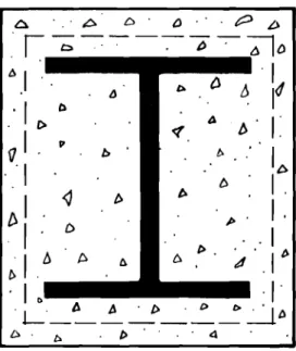
"Light" protection in this report means a relatively thin enclosure applied in the form of a box (Figure 1 (a)) or as a thin layer following the contour s of profile (Figure l(b)). "Massive" protection in this report means solid encasement without air gaps, having plane surfaces of either square or rectangular configuration (Figure 2).
The distinction between light and rna ssive forms of fire protection has been made for several reasons. First,
modern construction methods usually employ the light form of structural fire protection. Second, different heat transfer mechanisms are involved in each case. Third, massive
protection may contribute significantly to the carrying capacity of the structural unit.
Often units are constructed that do not fall clearly into either of the se categorie s . Sometime s box protection with core filling is used (Figure 3(a)). Configurations such as those shown in Figure 3 (b) are also difficult to clas s ify ,
This report does not cover such protection methods, but various techniques which will be presented may be adapted to other than light and mas sive forms of protection.
COLUMNS WITH LIGHT PROTECTION
The Scaling Method for Estimation of Fire Endurance
The scaling method may be used to estimate the fire endurance of structure s that are similar to one s for which te st data are available, and are heated under the same conditions, but are of different sizes. This device was first explored by McGuire (1-4) and has been used extensively in England
for the solution of fire resistance problems. It is not restricted in use to columns, but applie s particularly well to them.
(i) The Scaling of Heat Conduction Problems
The scaling of heat conduction problems is extremely versatile and may be applied to most practical cases. In this report, however, only the scaling of dimensions will be considered, as the scaling relation is intended to apply only to structure s composed of the same component materials.
The scaling relation permits the re sult of a time-temperature problem to be provided for a given structural element, if the re su lt on a similar element of another
dimensional scale is available. The latter may be obtained by any reliable method, usually by experiment. To apply the relation, a time scale dependent upon the scale of the
elements must be used. Therefore, where a time -temperature function (such as the standard test fire) is prescribed, any predictions based on an ordinary fire test result will apply to a furnace boundary condition referred to a scaled time. It has been found empirically that the introduction of a 0.8 power law substantially provides for the effects of the varying furnace boundary condition.
(ii) Advantage s and Limitations of the Scaling Method in Pure Heat Conduction Problems
The propertie s of a material affecting the proce s s of heat conduction (i. e. thermal conductivity, density and specific heat) generally vary with temperature. This does not affect the validity of time -temperature predictions because temperature is not a scaled quantity.
When water is present In a structure it absorbs heat as its temperature is raised and it is converted into steam.
It can be shown that these two effects do not influence scaling. Also, in fire te st s , water vapour migrate s away from the fire-exposed surface. Insofar as this is a diffusion proce s s ,
it should scale according to a square law relation.
The reliability of the scaling method maybe reduced when there are cavities or imperfect thermal contact at interfaces. When cavities exist in a structure, their effect on scaling may only be neglected if it can be seen from their
geometry in relation to the structure that they do not playa substantial part in the heat transfer. The thermal contact at interface s of composite structure s is never perfect and the heat transfer acros s the surface involve s proce s se s other than pure heat conduction. Normally, however, imperfect
thermal contact only amounts to the inclusion of a small thermal re sistance in a structure which already has a high thermal
resistance, and its effect on scaling may be neglected. (iii) The Estimation of Fire Endurance
The most simple and direct application of the scaling method is to columns on which the insulation follows the
core contour. When the core of a column is metal, its thermal conductivity is so high compared with that of the protective covering that it may be considered infinite. It is necessary to neglect the thermal capacity of the protective materials.
In the case of lightly protected columns, these two simplifications introduce only a small error. A column may thus be considered to be merely a thermal re sistance followed by a thermal capacity.
The fire endurance times of two columns of similar construction but not of complete geometric similarity are related by the expre s s i on
0.8
( 1 )
where R is the thermal resistance of the insulation, C is the thermal capacity of the core,
and t is the fire endurance time 1.
On substitution for Rand C where the thermal capacity of the insulation may be neglected
1
In the application of the scaling method to columns it must be as sumed that the fire endurance time is reached when the
core attains a given temperature. This should hold true for similar cores protected by cover which does not contribute to the bearing capacity of the unit.
where x
=
thickness of protection, in.D
=
de ve.loprne nt of insulation, in. (de ve Ioprnent of insulation is the length of the line drawn through the insulation at its centre)A = cross-sectional area of rneta.l coreZ, in. Z
The fire re sistance tirne of a contour protected rne ta l colurnn is directly proportional to the thickness of protection and the area of the rnet a l core, and inversely proportional to the de ve l oprne nt of the insulation, all raised to an exponent of 0.8.
(iv) Exa rnpl e
(2)
A c o Iu rnn protected by a 5/16-in. layer of sprayed asbestos3 collapsed under the applied load after 63 rni.n of fire exposure.
What will be the fire resistance ti rne of a s i.rrri l a r c o lu rnn protected with a 3j4-in. layer of sprayed asbestos and exposed to the s a rne boundary conditions? Substituting in equation (Z)
t l
=
(Xl Al DZf"8
-tz
x2 AZ Dl Al=
A2 D l=
43 in. D=
41. Z5 in. 2 t l 63 (3 4 x 41.25)
0.8 123=
=
ITlln 5 16 x 43A test on a c ol.urnn protected in the way described4 was te r rni.nat e d
2
For convenience, A rria.y be replaced by W - weight per lineal foot of the me ta l core.
3
Test No. F.R.O.S.I. 41Z. 4
after 2 hr. If the te st had been continued 3 min longer, the column would have collapsed. The first column had an average steel
temperature of 584°C at the point of failure while the second was at 568 ° C after 2 hr. An analysis shows that the temperature rise at this time is taking place at about 5 Co per minute. Hence, at 123 min the temperature would have been 583°C. This very close agreement between predicted and experimental results demonstrates the effectiveness of the scaling method in
problems of this type, when there are no serious complications that would invalidate the scaling law proposed.
Theoretical Evaluation of Fire Endurance Using Simplified One-Dimensional Heat Flow Analysis
A numerical calculation method has been proposed by Geilinger and Bryl (5). The procedure take s into account all factor s affecting temperature rise on the steel section, with the exception of pos sible disintegration of the protective material at high temperatures.
The one -dimensional model of a protected column is represented by a steel plate having a coating or protective material on the heated side and a perfect insulator on the other. The amount of heat nO, transferred during a time t per unit column length, is then given by
AO=(Tf-T
s)
u.
D. lit ( 3)where:
60
= heat transferred per unit column length III.f t
BtuK cal or m T f = furnace temperature in of or °C T = steel temperature in °F or °C s
U = thermal conductance ln Btu or K cal ft2 h of m 2 h °C
ft2 2
D = development of protection i n - - or m/m ft
6Q U D Lit
T s
=
W C=
(T f - T s) Cw
(4 )where: C
=
specific heat of steel in IbBtu°F or K cal kg°c
W = weight of steel shape in
セZ
orm
The thermal conductance (U) is dependent on the thermal
conductivity, thickness of insulation, and the surface coefficient of heat transfer. In general terms,
and A is
1
セ
.and R =
A
Z
R, where R IS the area through which heat isthe thermal resistance transferred. In this case,
Then U
=
D ( 1 R = -DHセ
+
セI
1 -D ( 5)where: h = surface coefficient of heat transfer in - - - - -Btu ft2 h of K cal m h
-c
or o r - - - - -K cal m2hoCk = t ermah 1 con uct rvrt y In ft hd . . . BtuOF (usually expressed as f (t))
x = thickne s s of insulation in ft or rn ,
The surface coefficient of heat transfer for a vertical plane surface may be taken as
h =
L
25セ
K cal m2hoC (6 ) or 0.279:f
Btu ft2 h ofSpecific heat value s for steel at various temperature s may be found among the references (e. g. 5).
When moisture is present, the stepwise evaluation of equation (4) must be interrupted to permit a calculation providing for the
effects of vaporization of the moisture. This is accomplished by as suming that all moisture vaporize s while the steel section temperature is at the boiling point of water. The vaporization of the moisture require s the following amount of heat:
where: f = moisture fraction
o
= bulk density (dry) of protective material inセ
r ft3 or
セ
3
m . k Cal
qw = latent heat of vaporization for water m kg
The time delay, t , is given by v f.x.P .q r w t
=--,....---,-v U 1 (Tf - T bw) or Btu lb (7)
where U 1 is the thermal conductance related to the middle of the insulating layer, and T b w is the boiling point of water.
2hk
U 1
=
hx+
2kAfter the effect of moisture has been accounted for, the stepwise calculation of equation (4) is continued until the limiting per-mis sible temperature on the steel section has been exceeded5.
(8 )
5
Harmathy (6) found tha t the increase in fire endurance over the dry condition of materials containing moisture was proportional not to the moisture content but to its moment about the fire -exposed surface. Specimens subjected to conventional conditioning procedures will ha ve symmetrical moisture distribution. Upon exposure to fire, however, moisture migration in the direction of heat flow will cause an unbalanced moisture distribution away from the fire -exposed surface, thus increasing the moment of the moisture content about that surface. Therefore calculations based on the simple vaporization of the moisture content often yield a lower fire -endurance time than is shown by
Equation (4) indicates that the fire endurance of a pro-tected steel column depends strongly on the ratio of the developed length of protective layer to section weight (DJW). This relation-ship is examined in more detail under "T'he Effect of Cros s-Section Size on Fire Endurance. "
The results of several analyses undertaken by the developers indicate agreement of plus or minus 10 per cent between calculated and experimental fire re sistance time s , A number of calculations carried out by the author of this report produced similar agreement. As the method applie s only to light protection 6, it should not normally be used in calculating fire endurance in excess of two hours. Heavy columns with DJW < 0.6 are an exception, and for such members the method presented here should be valid to fire endurance times of over 3 hours.
The advantage of this method rests primarily in its simplicity. Once the appropriate information for a material is known, an analysis can be completed in about one hour using only a slide rule. The simplifications inherent in the one -dimensional model of heat flow and the treatment of moisture effects necessarily render the method somewhat crude. It should therefore be used primarily for estimating purposes where specific fire test data are not available. Calculation of Limiting Temperature
The concept that a column exposed to fire will fail to perform its load-carrying function at a given temperature has already been introduced both in the alternate te st for structural steel columns and in the theoretical evaluation of fire endurance. For ordinary structural steel, a temperature of I 0000 F (538
0
C) is considered to be a failure criterion. The origins of the
10000F temperature criterion will now be investigated, and
some theoretical support for this limiting value of temperature
6 The method of Geilinger and Bryl yields the most accurate re su lt s when the protection follows the contour of the section. Where air gaps are present as with box or furred out protective coverings, calculated fire endurance times are conservative due to the beneficial influence of the air gaps.
as applied to ordinary structural steels will be provided. The applicable limiting temperatures for columns of ASTM A36 and ASTM AZ4Z steels designed in accordance with the National Building Code of Canada will then be examined. The present study will be confined to a treatment of axially loaded, pin-ended members, as the effects of end conditions and restraint on fire performance are not yet well understood.
Some investigators (5, 7) have used the classical concept of performance at ordinary temperatures as depicted in Figure s 4 (a) and (b) in the analysis of columns at elevated temperature. This model assumes a defined yield point which is equal to the proportional limit. The column thus fails eithe r by yielding or elastic buckling. This clas sical analysis of column action has been rejected as unrealistic and over - simplified, both at room temperature and at elevated temperature s ,
For present purposes, a method based on more refined room temperature column theory has been developed. The as sumption that normal column theory may be applied to members at elevated temperatures is based on the fact that compression members are relatively low-stressed and therefore not subject to significant creep deformations at temperature s up to I 0000F, provided the lateral deflections
remain small 7.
7 During fire te sts, it has been customary to permit a lateral defle ction of 6 in. or more in the United State s, and 3 in. in England and most European countrie s , For the purpose s of this work, however, failure will be taken as the point where lateral deformation due to axial load begins i , e. the point at which the column buckle s. Buckling means the point at which any structure or part of a structure pas se s from one deflection pattern to another without a change in load i , e. becomes unstable. In a fire test, this would correspond approximately to the point of maximum expansion. Point of maximum expansion means the time at which the column is at its maximum length during the fire test. The column temperature at this time is usually l e s s than the maximum temperature at the time of collapse. For te sts of short duration ( up to
zt
h r}, the points of maximum expansion and ultimate "failure" are separated by only a few minutes, but for longer fire test periods there may be a considerable time lapse between the two.(i) General Theory
Column action at normal temperatures has been very thoroughly inve stigated (8, 9). A limited amount of information is also available regarding compressive strength at elevated temperatures (i
o,
11). A comparison of the room temperature and elevated temperature compre s sive stre ss - strain curve s for wide flange sections has led to the analysis used in thisreport.
Figure 5 (a) shows the compressive stress-strain curve for a stub column and a coupon for the same wide-flange section. Figure 5 (b) shows a compressive stress-strain curve for a wide -flange stub column at 6500F. The defined yield point
has disappeared at this temperature and at yield stre s s level, as determined by the 0.2 per cent offset method, the curve has flattened sufficiently to regard its slope as being equal to zero. This shows that the behaviour of a short wide-flange column at elevated temperatures is similar to the behaviour of a column having residual stresses {CYrd at ro o rn temperature. Examinations of long slender compression members at high temperature s (I2, 13) have shown that experimental re su It s and the Euler theory for elastic buckling show good agreement.
On the basis of the literature examined, therefore, it will be as sumed that the ultimate strength curve of a wide flange column takes the form shown in Figure 5 (c), provided that buckling takes place about the weak axis. The first portion is a straight line joining the yield stress and the
proportional limit at the point of transition to the long column
range. The other portion is the Euler curve. This curve has the form 2
TIE CY =
and the transition point to the
Euler range is given by I/r (limit) 0 /
セ
where (I is the critical stre s s for elastic buckling,
cr
E is the modulus of elasticity,
0" is the proportional limit, and p
l/r is the slenderness ratio.
(ii) Limiting Temperature for Ordinary Structural Steels
(10)
A large number of building columns fabricated from ordinary structural steel (ASTMSpec. A 7) were subjected to fire test (10) during the early part of this century. The
results of these tests form the basis for the 1000°F temperature criterion applied to steel columns in the alternate test. As
the columns all had a slenderness ratio of less than 120, they were
designed in accordance with the formula (Tall
=
16, 000 - 70 l/r (11) as recommended by the American Institute of SteelConstruction at that time.
Table I gives the average properties for a minimum 8 specification A 7 steel, as taken from information in the literature. The minimum slenderness ratio for applicability of the Euler theory has been calculated using equation (10) and entered in the last column.
8 Tensile te sts on material taken from columns to be fire tested always showed strengths considerably in excess of the minimum required by the specification.
Figure 6 shows the ulti.rnate strength curve s for c ol.urnn s of rrrinimurn specification A 7 steel having a slenderne s s ratio of 120 or less for te mpe r atu r e s between 500 and 1000°F. It
is noted that under the applied loading no co lurnn in the slenderness range 0 to 120 would fail at 1000 ° F. In fact, an average re sidual safety factor of appr o xi mat.eIy 1.2 re rna in s at this te mpe r atu r e .
Actual average failure te mpe r atu r e s , as dete r rrrin ed by test, were generally well in excess of 1000°F. This is to be explained as follows:
(1) The protective covering of the c olurnn s under test (in rna n y cases concrete) made a considerable contribution to the load -carrying capacity of the unit;
(2) The properties of the steel in the c o lu.rnn s tested were s ornewhat better than required by the rrrirrirnurn speci-fication of A 7 steel;
(3) Many of the te sts were of long duration (up to 8 hours) and failure took place by creep buckling, which is beyond the scope of the present me thod of analysis.
The current AISC r e c ornrnerida.t ion (15) pe r rnit s a design stress of
(Tall ::: 17,000 - 0.485 P> s ,i , for -1
r < 120 ( 12)
This de sign curve has also been plotted in Figure 6 for c orrrpa ri s on , It is seen that when designed in accordance with equation (12), only c o lurnn s with l/r < 30 are theore-tically safe at an average te rnpe r a.tu r e of lOOO°F, and c o lurnn s with
1/
r セ 65 will fail at an average te rnpe r a.tu r e of 900°F. The results of a nu rnb e r of published (16, 17) and unpublished fire tests on c o lurnn s loaded in accordance with the de sign rne thod of equation (12) showed failure atan average te rnpe r atu r e of 950-1000°F at the critical sections. The se re sults showed close ag r e e rne nt with the theoretical analysis for the c o lu rnn s considered.
The present analysis shows that the 1000 ° F Hrnit ing average t.e mpe r atu r e criterion for structural steel c o lurnn s was well Justified by c o mpa r i s on with both e xpe rirne nt a l and theoretical approache s , Change s in structural de sign
procedure, however , have now caused the 10000
F temperature to be less conservative in some cases. This development emphasize s the danger in altering structural de sign methods without making corre sponding change s in the fire evaluation procedures.
Some central European countries have recognized this danger and set the limiting average temperature for structural steel columns at 4000
C (7520
F) in the fire te st standard (18). They now permit, however, a loaded column test in which the temperature criterion is waived. Columns tested under load usually show a considerably higher average temperature at failure than that permitted in the alternate te st. They have apparently been conservative in as signing the value of the temperature criterion in order to encourage continued fire te sting of structural steel columns under applied load.
(iii) Columns Designed in Accordance with the National Building Code of Canada 1965, (19)
The Code pre scribed that the allowable axial compre s sion on the gross area of columns and struts be given by
(20,OOO_70 k l)
((Ty
)
Cla ll = r 33,000 (13 )
but not to exceed 145,000,000 (kl/r)2
(14 )
where kl is the effective length of a member of unsupported length 1,
r is the radius of gyration applicable to this length, and
(T is the specified minimum yield strength of the steel.
y
Equation (13) plots as a straight line sloping downwards, while equation (14) is a factorized Euler curve.
In this section compression members having a slenderness ratio from 0 to 200 (the maximum permitted by the Code) are analysed. Main compression members such as columns should not normally have a slenderness ratio exceeding 120.
(a) Colunms of AST M Specification A- 36 Steel. The average properties of a minimum specification A-36 steel have been plotted in Figure 7 and reproduced in Table II for
temperature s from 500 to 1000 ° F, in 100 ° intervals. Data have been taken from the re sults of unpublished te sts as well as
from the literature. Equation (10) has been used to calculate the minimum slenderness ratio for applicability of the Euler theory which has been entered ir.. the last colunm of Table
II.
For A-36 steel the transition point between equations (13) and (14) is found by simultaneous solution of the two equations to be at k 1/ r = 99. The transition point for an A-7 steel (Oy
=
33,000 psi) is 108. The "long c o lu mn range"begins at a lower slenderness ratio with the higher strength steels. Figure 8 shows the ultimate strength curve s for columns of A-36 steel for temperatures ranging from 500 to 1000°F. The safety factor against buckling at room temperature and
at 900 ° F is plotted in Figure 9. The analysis shows that c o lu rnn s having llr
=;
45 may be unsafe at 900°F, and that no columns are capable of supporting the NBC design load at 1000°F.It is unlikely that many col.urnn s would fail under load at 900 ° F, because most steels are much stronger than the minimum specified. Strength and proportional limit are the significant parameters up to the long column range. Figure 10 shows the properties of a typical as-rolled A-36 specification steel te sted at DBR and Figure 11 shows the ultimate column strength curve for this steel from 500 to 1100 ° F, in 100 ° increments. At 1000°F, c o lurnn s having a slenderness ratio of llr セ 92 are not in danger of collapsing under the NBC
design load. This analysis serves to demonstrate how significantly the failure temperature is influenced by varying properties of
the material. It is worth noting that most wide -flange columns that were fire te sted under load in the past had a slenderne s s ratio of less than 90.
(b) Columns of ASTM A-242 Steel. The column strength of a wide -flange section rolled from low-alloy, high- strength steel will now be examined at elevated temperature s , in
relation to design methods required by the National Building Code (1965). The method for analysis is the same as was used for A-36 steels.
The average properties of a ITliniITlUITl specification ASTM A-242 steel have been plotted in Figure 12, on the
basis of data gathered fr o m the literature. Published i nfo r rriat i on regarding proportional lirnit is rather scant and the e sti mat e d value s plotted rria y be on the low s ide by as rnuc h as 15 pe r cent in SOITle cases. Figure 13 shows the ult irnate strength curves for te mpe r atu r e s ranging fr orn 50QoF to 1000°F in 10Jo incre-rrie nt s ,
All c o lu mn s are capable of supporting the de sign load at 700°F. At 800°F, c o Iurnn s with a slenderness ratio between 50 and 80 rna y fail. Only stub co lurnn s are theoretically
capable of supporting the de sign at 900 ° F. Unfortunately, no fire test data on loaded c o lurnn s for this type of steel are available, so these findings have yet to be substantiated by e xpe rime nt a l evidence.
(i v) SUITlITlary
The failure of wide -flange steel co lurnn s under load and fire test rnay be calculated quite simply if the fire exposure
tirrie does not exceed a.pp r o xi rnat e l
y zt
hours. The effect ofthe fire exposure in this case is rne r eIy to d irninis h progressively the design safety factor to a value of 1, at which point the
c o Iurrm collaps e s ,
Detailed analysis of c o lu rnn s rolled fr o m COITlITlon
structural steels has shown that the average failure te rnpe r atu r e rna y range fr orn 750°F to over lOOO°F. In rrio st cases,
therefore, creep-buckling rnay be ruled out as the rne c ha nis rn of failure when c o lu rnn s are stressed in a rna nn e r pe r rni.tt e d by present design rrieth od s , This finding is substantiated by excerpts fr orn a r e po rt is sued by the Wright Air De ve l oprrie nt Center (20): "Tests on stainless steel Type 302 indicated that creep-buckling was not a design p r obl e m for this alloy up to te mpe r atu r e s of 100uoF. For c o Iurnn s tested in creep at 1000°F, loads which were 97 and 94 per cent of the irnrrie d i at e failure load were supported for 132 and 185 hours, respectively. Co Iurnn design for 1000°F could, therefore, be based on static properties (stress-strain curve) for this alloy . . . . If the design is for an e xt r e rrie l y shor-t e l.ifet irne application, it rna y
resistance to creep. Design may then be based on short-time strength parameters." The latter statement is particularly applicable to carbon steel columns exposed to fire temperatures.
The analysis has shown that the IOOO°F temperature cri-terion of the alternate test is in some cases too liberal, although it originally provided results consistent with observations. It should be kept in mind, however, that all analyse s as sume absence of temperature differences inside the steel section. In an actual case, this condition is approximated only in very light sections. In fire tests, the temperatures are always measured directly on the steel surface and the "coren is somewhat cooler. For columns designed in accordance with NBC requirements, therefore, the present permissible temp-erature limits will in most cases be satisfactory.
The Effect of Cros s -Section Size on Fire Endurance
Although it has long been realized that the size of a column eros s - section will affect the fire endurance of a
member with a given protective cover, no formal investigation of the subject can be found in the literature. It has generally been assumed that the change is not significant, and various technical bodies have treated the matter rather superficially.
For example, Supplement No.2 (21), Section 2.6 reads as follows: "A.s the size of a column increase s, the fire endurance become s greater for the same thickness of cover. The fire resistance ratings obtained from Tables 2.6. 1 and 2.6.2 apply to columns of the minimum size permitted by the structural requirements of the National Building Code. Increased values of fire
resistance may be obtained for larger columns but these should be justified by te st. II The CSA Standard for fire te st s,
(22), in the alternate test of protection of steel beams and girder s state s that: "The te st re sult shall not be applicable
to beams or girders smaller than that included in the specimen.It
No such clause, however, is noted in the alternate te st of protection of steel columns.
It appears useful, therefore, to employ the scaling method to study theoretically the variation of fire endurance time with increasing section size for a given thickness of protective cover. This is accomplished by making use of a modified form of equation (2)
=
0.8
( 1 5)
where W is the section weight in lb per ft, and the other terms have the meanings previously defined.
The development of the insulation (D) is given by
D = 4B
+
2H - 2w+
4x for contour protection ( 1 6) where B=
width of flangeH
=
depth of section w=
thickness of webx
=
thickne s s of protectionFor 0 < x
>
1 inch, no significant error is introduced by ignoring the change in (D) due to variation in the magnitude of the term (x). This simplification is necessary in order to permit generalization of the re sult s ,The fire endurance times for various common sections protected with 5/l6-in. sprayed asbestos have been calculated and are tabulated in Table III for contour protection and the results have been generalized and plotted in Figure 14 (a, b). It is seen that the significant column parameter governing the variation of fire endurance is D/W, the ratio of the developed insulation to the section weight.
A very light section (6 in. x 6 in. x 15.5 lb) has been chosen as a reference, and all other fire endurance times are referred to the basic fire endurance time (FE0) for this section.
For a heavy square section (12 in.x 12 in. x 190 Ib) the fire endurance time is increased by a factor of 3.92 for contour protection. Unfortunately, experimental information to substan-tiate the validity of this analysis is not available at the present
time. Inasmuch as the scaling method is reliable in other problems, however, it may be assumed that calculated results are correct if the protective cover remains in place.
At the present time, some of the most massive column sections ever used in steel construction are being erected at the Toronto-Dominion Bank tower in Toronto. The theoretical fire endurance of the shape s shown in Figure s 15 and 16 has been examined.
For column sections that are not protected against fire, it may be assumed that the fire endurance time varies with mass in the same manner as it does for protected sections. A member without mas s would have a theoretical fire endurance time of 5 min according to the ASTM or CSA standard alternate te st (because the furnace average temperature reache s 10000
F at this time). The fire endurance of a real column with
finite mass will always be greater.
For example, an unprotected rolled lIH" section weighing
34i
Ib per ft yielded a fire endurance time of IIi min 9 when tested under load. The fire endurance times for other structural steel shapes tested varied from 9 to 19 minutes.The 8 in. x 8 in. x
34i
Ib section mentioned above was as signed a fire endurance time of 10 min on the basis of the test result. By use of the scaling method 10, it was found that an unprotected steel column having the dimensions shown in Figure 15 would support load for 2 hr in the standard fire te st. The even larger section shown in Figure 16 would yield a fire endurance time of approximately2i
hr.It is impractical to validate these findings by experiment, due to the bulk of the member in question. Even if the theoretical fire endurance of a massless column (5 min) is used as a basis for calculation, however, the members previously mentioned would have fire endurance times of 1 and Ii hr , respectively.
These values may be regarded as reliable minimum fire endurance periods for the two massive members which were studied. If
the member shown in Figure 16 were contour sprayed with 5/l6-in. asbestos cover, its fire endurance time would be increased to
8.4 hr.
9
Ref (16), Test No.
1.
10 The scaling method may be reasonably applied to the problem of an unprotected column by considering each member to have a very thin insulating layer. The effect of this hypothetical insulating layer is assumed to increase the fire endurance time from the theoretical 5 min to the assigned 10 min.
This study has clearly demonstrated the significance of the influence of column size and shape on the fire endurance time. If designers were permitted to account for these factors in specifying fire protection, substantial savings in the cost of the protection could be achieved.
COLUMNS WITH MASSIVE PROTECTION
Extension of Scaling Method for Estimation of Fire Endurance To predict the fire endurance of columns provided with mas sive protection, the scaling method must be extended to include the thermal capacity of the encasement. The heat transfer is assumed to be largely into the column flange and the thermal capacities of the cover and the core are added together. Good results are obtained for gravel concrete if one -half of the room temperature thermal capacity is used.
On the basis of these assumptions the modified scaling expression becomes
0.8
( 17)
where M is the combined thermal capacity of the insulation and core. Table IV compares fire endurance times predicted according to this procedure with experimental test results.
Although agreement between predicted and experimental re sults is reasonable, it is not nearly as good as in the case of protections following the column contour. This is due in part to the simplifying as sumptions which were made, as well as to varying concrete strengths (hence failure at slightly different core temperature s}, and spalling of the concrete.
All the predictions in Table IV are for column sections smaller than the one used as a basis for prediction. Attempts to use this method to predict fire endurance times for larger columns encased in concrete do not re suIt in good agreement with experimental results because the cover suffered more severe deterioration with the larger sections. It should be noted that spalling and cracking of the concrete also reduces the load-bearing capacity of the composite unit.
Numerical Evaluation of Fire Endurance U sing Simplified One -Dimensional Model
Heat flow in a column enveloped in flames on all sides is two-dimensional when the ends are insulated to prevent heat transfer. Solution of a two-dimensional, unsteady state, heat transfer problem pre sents many difficultie s , except with the use of a high-speed digital computer. A simplified model developed by G. Williams -Leir 11 was therefore used to study heat flow into a column having concrete protection.
The model reduced the complex problem to a one-dimensional heat transfer problem by assuming that the actual situation is analogous to a plane wall having three homogeneous layers or laminae, the centre of which is steel, and with the sides perfectly insulated. Both faces of the wall are as sumed to be exposed to the furnace temperature. This
results from the assumption that heat transfer occurs through the thinner concrete to the flange, and through the thicker
concrete to the web. Referring to Figure 17, which illustrate s the model, the following relations are obtained:
a
=
C+
B/2c = C
b
=
A/Bwhere A is the cross-sectional area of the steel section. It was further assumed that material properties are unchanged throughout the fire exposure and the following value s were employed as input data:
Steel: k = 23 Btu/ft. h°F
o
= 490 Ib/ft3 C =.11 Btu/lb. of 11 Private communication. (l8a) ( lSb) (18c)Concrete: k
=
0.54 Btu/ft. h. 0Fo
=
144 lb. ft3c = 0.2 Btu/lb. of
where: k = thermal conductivity p = bulk density
and c
=
specific heatA calculation was performed to determine the fire endurance time of the familiar 8 in. x 6 in. x 35 lb. RSJ section, protected by 2 in. of siliceous aggregate concrete encasement. Figure 18 shows the temperature profile
in the model at significant intervals. It is seen that an average steel temperature of 1000 ° F was attained at approximately
3i
h r , and at 3 hr 40 min the average steel temperature was 1115°F. In Figure 18, the temperature distribution in the "flange" and "core" concrete is noteworthy. Temperatures in the "core" adjacent to the steel may be expected to beconsiderably below those in the "flange."
It
follows that during later stages of fire test the "flange" and outer portionof "core" concrete make little contribution to the strength of the structural unit.
The model was also employed to study the influence on fire endurance of column size and shape. As with the scaling method, and for the same reasons, computed results for large c o lurnn sections yielded fire endurance times
con-siderably greater than those derived by experiment. It is concluded, therefore, that with dense aggregate concrete protection, all predictions or calculations of fire endurance
should be approached with extreme caution.
This model proved to be most useful in estimating the temperature profile s expected in a concrete protected column. This information contributed greatly to the develop-ment of the structural analysis pre sented in the next section.
Calculation of Limiting Temperature
If the encasement has considerable compressive
strength and is bonded to the steel, as is the case with concrete protection, the load capacity of the structural unit may con-siderably exceed that of the steel shape alone. Composite action will be present, whether it is contemplated by the de sign or not. With concrete protection, the structural unit more closely resembles a reinforced concrete column than it doe s a simple steel column.
It is, therefore, que stionable whether the limiting steel temperature concept is applicable to combination columns. Because temperature gradients in the steel core are relatively small, however, the steel temperature remains the be st basis for any analysis or prediction. The limiting temperature will be different for all except identical columns. A method for determining the critical core temperature for any concrete encased wide -flange column developed by the writer is presented here.
It is as sumed that the ultimate strength of the column at any time is given by the equation
P = A (J (T )
+
A f .(T ), T = f (t)s y s c c c
where (J = yield strength of the steel at te rr.pe r atu r e T
y
A
=
cross-sectional area of steel section sT
=
average temperature of the steel core sf • = ultimate compressive (cube) strength of concrete c
A = effective cross-sectional area of concrete c
T
=
average concrete temperature cThe variables A c and T c are obscure. Malhotra and Stevens (24) have suggested that considering A c to be equal to the nominal dimensions of the steel column provide s
reasonable results. The results of the computer study in the previous section strengthen the validity of this assumption.
The "average concrete temperature," cannot be determined by any simple procedure. Examination of extensive fire te st re sult s indicate s that T c will approximately equal the temperature measured on the web of the steel column
[i.
e. T c = f[T s}J.Figure 19 shows this relation for a column with a 2 -j.n , cover of stone aggregate concrete. The results of computer analyses showed this to be a reasonable as surnpt ion , Reference s regarding variation of steel and concrete strengths with temperature may be found in the literature, and typical curves are shown in Figure s 20 (a) and (b).
The method of calculation of critical core temperature is be st illustrated by an example. Suppose it is required to deter-mine the fire endurance time of an 8 in. x 6 in. x 35 lb rolled steel joist with a rectangular cover of 2-in. gravel aggregate concrete having an average cube strength of 3. 75 ksi. The yield of the steel is taken at 33 k s i , Table V shows how the temperature at collapse may be determined by employing eq. (19). Then by examining the temperature rise curve of a similarly protected column (Figure 21), the fire endurance time may be estimated.
The estimated fire endurance time is very close to that deter-mined by experiment. This exercise demonstrate s that once the pro-perties of the materials are known, fire resistance may be predicted. CONCLUSION
The behaviour of simple steel columns at elevated temperatures has been subjected to analysis by methods familiar to most engineer s. By use of available fire test results and application of the methods discussed in this report it is possible to assess the expected fire endurance time for most forms of column protection.
At the pre sent time analytical approache s to fire endurance problems are hampered by the scarcity of information about
the elevated temperature properties of protective materials. For this reason, methods that can be used to extend existing fire te st re sults have been emphasized rather than procedure s that enable calculation of fire endurance in the absence of fire te st data. Essential information about the elevated temperature properties of building materials is being as sembled by a number of intere sted re search worker s , Once this information become s more generally available to engineer s, analytical approache s to fire endurance problems will undoubtedly be more widely accepted.
The procedures used to analyse fire endurance problems do not normally lead to a straightforward solution. Instead they proceed by trial and error approach which may require a good deal of experience arid insight on the part of the engineer. This situation is by no means restricted to the field of fire
technology, and has been accepted as normal in many fields of engineering other than fire technology.
SYMBOLS
A cross - sectional area in.
2
m2
B width of section flangeD development of insulation E - modulus of elasticity FE - fire endurance time
H depth of section
M - effective thermal capacity
in., rn In., m minutes in., rn Btu IboF Q - heat quantity R - thermal resistance T - temperature U - thermal conductance Btu, Kcal HZ h °F Btu Btu m 2
h OC
Kcal KcalW - weight of steel section per unit length c - Specific heat lb, kg Btu lb of Kcal kg °C f I
C ultimate compressive (cube)
h surface coefficient of heat transfer
k - thermal conductivity
Btu
Btu Kcal
m hoe
1 - effective length of column
latent heat of vaporization of water
A,
m Btu lb Kcal kg r radius of gyration t - time x - thickne s s of insulationクセセャ
J -
cartesian coordinateso
-
bulk density i.n , , m minutes, hours in , , ft, mE
3 m o stressO - permissible design stress
all o - residual stress rc € strain Subscripts: c - pertaining to concrete f - pertaining to furnace p - at proportional limit s - pe rtaining to steel u - at ultimate load y - at yield stre s s level
REFERENCES
1.
McGuire, J. H. The Scaling of Dimensions in Heat Conduction Problems. J. F. R. 0., F. R. Note No. 94/1954, Jan. 1954.2. McGuire, J. H. The Scaling of Dimensions in B. S. 476 Fire Resistance Tests. J .F.R.O., F.R. Note No. 95/1954, Jan. 1954.
3. McGuire, J. H. The Scaling of Heat Conduction Problems. J .F.R.O., F.R. Note No. 98/1954, Feb. 1954.
4. McGuire, J. H. The Estimation of Fire Resistance. J.F.R.O., F.R. Note No. 348, March 1958.
5. Geilinger, W. and S. Bryl. Feuersicherheit Der Stahl Konstruktionen, IV. Teil: Feuerschutz von StahlstUtzen. Verlag Schweizer Stah.lbauverbank, Zurich, 1962.
6. Harmathy, T. Z. Effect of Moisture on the Fire Endurance of Building Elements. ASTM Special Publication No. 385, Chicago, June 24, 1964.
7. Cuomo, Salvatore. Sulla Resistenza Dei Pilastri Di Acciaio Alle Elevate Temperature. LtIngenere, No.5, Rome, 1960.
8. Beedle, Lynn S., and L. Tall. Basic Column Strength. American Society of Civil Engineers, Proceedings,
VoL 86, No. S T 7, J uly 1 960 .
9. Beedle, L. S., T. V. Galambos, and L. Tall. Column Strength of Constructional Steels. Lehigh Univ.,
Beth-lehem, Pa , Fritz Engineering Laboratory, Reprint No. 177.
10. Inberg, S. H., and P. D. Sale. Compressive Strength and Deformation of Structural Steel and Cast Iron Shapes at Temperatures up to 950°C (1742°F). Proceedings of the American Society for Testing and Materials, Vol. 26, 1926, p. 33.
11. Sale, P. D. Compression Tests of Structural Steel
at Elevated Temperatures. National Bureau of Standards, Journal of Research, Vol. 13, R. P. 741, Washington, Nov. 1954.
12. Dubuc, J., V. N. Krivobok, and G. Welter. Studies of Type 301 Stainless Steel Columns. ASTM Special
Technical Publication No. 196, 1957.
13. Dubuc, J. and G. Welter. Compression and Buckling Characteristic s of Annealed and Aged Inconel 718 Nickel-Chromium Alloy at Temperatures up to l400°F. ASTM Special Technical Publication No. 303, 1961.
14. Ingberg, S. H., H. K. Griffin, W. C. Robinson, and R. E. Wilson. Fire Tests of Building Columns.
Technologic Papers of the Bureau of Standards No. 184 U. S. Dept. of Cornrn; , National Bureau of Standards, Washington, 1921.
15. American Institute of Steel Construction, Steel Construction Design Manual, 5th ed , , New York, 1961.
16. Galbreath, M. and W. W. St an zak , Fire Endurance of Protected Steel Columns and Beams. National Research Council, Division of Building Research, Technical Paper
No. 194, Ottawa, April 1965. NRC 8379, p. 20 (Table 1. 8. A. ) 17. Mitchell, N. D. Fire Te sts of Columns Protected with Gypsum.
National Bureau of Standards, Journal of Research, Vol. 10, 1953.
18. German Engineering Standards, DIN 4102.
19. National Building Code of Canada (1965). Issued by the Associate Committee on the National Building Code, National Research Council, Ottawa, March 1965. Section 4.6, Steel Construction, Subsections 4. 6. 12 and 4. 6. 1 3.
20. WADC Technical Report 52-251: Investigation of Compression Creep Properties of Aluminum Columns at Elevated
Temperatures. Wright Air Development Center, 1954. The Compressive Creep Buckling of Metal Columns. Wright Air Development Center, Oct. 1958.
21. Supplement No.2 to the National Building Code of Canada. Fire Performance Ratings, 1965. Is sued by the As sociate Committee on the National Building Code, National Research Council, Ottawa, Canada.
22. Canadian Standards Association, CSA Standard B54. 3-1964. Methods of Fire Tests of Walls, Partitions, Floors, Roofs, Ceilings, Columns, Beams and Girders. April, 1964. 23. D. S.1. R., J. F. R. 0., Ashton, L. A. and P. M. T. Smart.
Sponsored Fire -Resistance Te sts on Structural Elements. London, Her Majesty's Stationery Office, 1960.
24. Malhotra, H. L. and R. F. Stevens. Fire Resistance of Encased Steel Stanchions. Proceedings of the Institution of Civil Engineers, Vol. 27, Jan. 1964, p. 77.
Temperature
E x 10- 6 (psi)
of CJ
y (ksi) (Jp (ksi) ljr (minimum)
500 27.5 16.0 24.5 123 600 26.0 14.0 22. 7 126 700 24.7 12.0 19.0 127 800 23.0 10.0 16.6 129 900 21. 5 8. 1 14.4 133 1000 19.5 6.5 12. 5 138
Temperature E
of (ksi) (ksi) (psi x 10- 6) 1jr(min)
500 17,500 30,000 24.5 118 600 15,200 28,500 22.7 122 700 13,000 27,000 19.0 121 800 11, 000 25,000 16.6 122 900 8,700 23,500 14.4 128 1000 7,100 21,500 12.5 132
Protected With 5/16-in. Sprayed Asbestos
Section':' D (in. ) FE (min) FE/FEo D/W (in. ft)
1b 6 x 6 x 15. 5 1b 36 35 (FEJ 1. 00 2.32 8 x
6i
x 24 1b 42 431.
23 1. 75 12 x6i
x 31 1b 51 461.
311.
65 16 x 11i
x 88 1b 110 57 1. 631.
25 lOx lOx 49 Ib 60 58 1. 66 1. 22 8 x 6 x 35 1b':C':C (BSB) 41. 3 60 1. 711.
18 12 x 12 x 65 1b 72 631.
80 1.11 36 x 12 x 150 1b 120 81 2.32 0.80 24 x 14 x 160 1b 104 97 2.77 0.65 lOx lOx 100 1b 63 99 2.83 0.63 36 x 12 x 194 1b 120 100 2.85 0.62 36 x16i
x 245 Ib 138 110 3. 14 0.563 36 x16i
x 300 1b 138 127 3.63 0.46 12 x 12 x 190 1b 80 137 3.92 0.42':'Protected by thin contour sprayed asbestos (x
=
5/16
in. ) ':":'Reference 23 Test No. F.R.O.S.I. 412.Test Fire Endurance No. ':< Type of Column Time (by te st ) C.2 8 in. x 6 in. x351bRSJ, 2 in. cover 3-39 C.67 6 in. x 42:1 In.. x 20 Ib RSJ, 2 in. cover 3-08
C.IOO 4 in. x
3
in. x 10 Ib RSJ, 2 in. cover 2-50 C.62 4 in. x 3 in. x 10 Ib RSJ, 1 in. cover 1-30 C.64 4 in. x 3 in. x 10 Ib RSJ, 4 in. cover 6-00Predicted Fire Endurance Time 3-03 2-31 1-18 5-36 ':CInvestigations of Building Fires,
Part V. Fire Tests on Structural Elements by L. A. Ashton and N. Davey. National Building Studies, Research Paper No. 12,
Test No. C.2
Section: 8 in. x 6 in. x 35 lbl ft Rolled Steel Joist, Cros s -Sectional Area
=
lOin. 2 Test Load: 202 kips 2Effective Concrete Area: 48 in. セZ\
Steel Temp. Yield Load on Mean Concrete Temp. Concrete Load on Column
Strength Steel Strength Concrete Capacity
of °C (ksi) (kips) of °C (ksi) (kips) (kips)
932 500 19.3 193 752 400 2.85 136 329 968 520 17.5 175 779 415 2.80 134 309 1004 540 15.75 157.5 815 435 2.58 124 281.5 1040 560 14.0 140 842 450 2.45 118 258 1112 600 11.0 110 869 485 2.15 103 213 1148 620 9.75 97.5 941 504 1. 96 94 191. 5
セZGiョカ・ stigations of Building Fire s,
Part V. Fire Tests on Structural Elements by L. A. Ashton and N. Davey. H. M. S.0., London, 1953.
Critical Temperature: lI30°F, 610°C (approx)
Estimated Fire Endurance Time: 3 hr 37 min (Figure 21) Actual Fire Endurance Tirne by Test: 3 hr 39 min
FIGURE 1
EXAMPLES OF LIGHT PROTECTION
6
I "
bo • t) A 'I
A . . . /j UIV
.I
(;l . 1 > ' セ 4/>'1:
(jI,
I> , b ' b , .' 'I
.I
.
b" 1
'" '
o :
I.
セ
I '
b . J>'I,
I .
D p ....I
セ
'16
A t . 6,'<:1.1 c>. .. I
セ.,.
,L
, t > A · / > · f > セBiOェ ----l {;>. b . / > " ' 4 'FIGURE
2
MASSIVE PROTECTION
-.
1
/]
t:
,1
セ
'"l.--
セ{---
c.--.. ""
I
セ
"
-)
セ(a)
(b)
FIGURE
3
EXAMPLES OF COMPLEX PROTECTION
FIGURE
4(a)
IDEALIZED STRESS-STRAI N CURVE FOR CARBON STEEL
1 . - - - -
f1z
FIGURE
4(b)
ULTIMATE STRENGTH CURVE OF IDEALIZED COLUMN
iMセ
Stub
OY
-r--
]o-RC
op .
-FIGURE
5(a)
I II
llP -
I
I
I
I I I I I IFIGURE
5(b)
L - - - f 0 .
FIGURE
5(c)
81i セッョMU20
10
e - - eA I SC Des i 9n Cu rv e
rF
=17,000 -
O.
485
ゥOセR
セ-
MセA I SC Des i 9n Cur v e
rF
=16 000 - 70
,
l//v
o
o
20
40
100
120
140
FI GURE
6
ULTIMATE MINIMUM STRENGTH CURVES FOR COLUMNS OF
A7 STEEL AT TEMPERATURES UP TO 1000°F
0,
3
0,
0,
<»
0,
0,
-
"'0
0,
セi\ZI
"'-0
0,\
セMG2
"'0
-
セ
"'0
<,
0
0<:
30
0-0__
0
--....
E
0
-0--...,.
0",
"
0
0
0,
-,
1
0,
0
20
V')0,'0
a..
0"'-0'0
\0 IBッセ
0,
- '<:)
10
x UJa
1200
1000
400
600
800
TEMPERATURE, of
200
0'---'--...
- . & . . . . - - - 1 . . -...- . . & . . . . - - - 1 . -...- . . . 1 . . . . - - - 1 - _o
FIGURE
7
AVERAGE COMPRESSIVE PROPERTIES OF ASTM A36
STRUCTURAL STEEL
10
Notes:
(1) Strong Axis Buckling (2) Weak Axis Buckling
(3) Normal Scatter for Failure Points of Wide Flange Columns Tested at Room Temperature Estimated Scatter for Failure Points of Columns at 900°F 220 200
180
160
140
120
100
80
60
40
20OL-_ _
...L---....L.---...L---I...---L---!-_-I....---..L..---...l....--...- - - - 'o
FIGURE 8COLUMN STRENGTH OF A-36 STEEL WI DE FLANGE SECTIONS
/°"'0
2
0u
70°F
0 0 セッ 0 I -V1 0 Z«
セ«
>-90QoF
l -•
•
u.J1
b
-
...
0 l.L.MNZZZコZZコZココ_ztセN^
«
V1 l.L. 0Columns Unsafe
c::: -0 I -U«
o;
=
0
l.L.I
II
0
0
50
100
150
200
1//(,
FIGURE
9
SAFETY FACTOR AGAINST BUCKLING OF WI DE FLANGE COLUMN
SECTIONS OF A-36 STEEL, AT 70°F AND 900°F
1
V')a..
セ I o .-410
><o
1200
1000
400
600
800
TEMPERATURE, of
200
OL...---L._...J...-_.L....---L._...J...-_.L....----J.._..._.J....----J.._...L...----Ja
FIGURE 10
COMPRESSIVE PROPERTIES OF A TYPICAL ASTM
SPECIFICATION A-36, AS ROLLED STEEL
40 30
20
10o
o
20
4060
80
100
1/A.
120
140160
180
200 FIGURE 11COLUMN STRENGTH OF TYPICAL A-36 STEEL AS ROLLED WI DE FLANGE SECTIONS
bセ
0...0
o""-0
4
"
"-0
o""'0
o,
"'-0
or;
"0
'-'0
"-0
-\
セB
セiッ
3
30
セNNNNNMャ-
セ
セ
02
20
V')0"
0...
0
a..
I
セ0...
0
I 0 ...-l1
0
10
>< L..LIo
1200
1000
400
600
800
TEMPERATURE, of
200
OL---L.._...I....-.-L....----L.._....l....-_L...----'-_...r....-_I...---I..._...r....---'o
FIGURE 12
AVERAGE COMPRESSIVE PROPERTIES OF ASTM
A-242 STRUCTURAL STEEL
o
200 180 160 140 120 80 60 40 20o
o
80 I'-IIV セ セ >-... 60 u « a.. « V) u セ I..LI 0:: セ ::> ... « 0:: I..LI 20 40 a..:=E I..LI ... :=E 0 0 0:: u. 0 'PP-10 20 FIGURE 13COLUMN STRENGTH OF A-242 WI DE FLANGE SECTIONS
lャNjiセ
u.. u..O<x<linch
3.0
2.0
セ o2. 5
2.0
1.5
1.0
O. 5
1. 0
L . . . - - ....L...- ---'- ----' セ ____""to--...Jo
D W FIGURE 14(a)FIRE ENDURANCE OF WIDE FLANGE COLUMNS WITH THIN CONTOUR PROTECTION
o
1
. 1
. 0
1
o
<x
<1
inch
0"\
\
,
,
,
,
,
-,
,
10
FE
FE
0
100
FIGURE
14(b)
FI RE ENDURANCE OF WI DE FLANGE COLUMNS
WITH THIN CONTOUR PROTECTION
00
FIGURE
15
BUILT-UP COLUMN - 3 PLATES
'IF
22
x
183/8
x
31/3
at
734
FIGURE
16
BUILT-UP COLUMN - 2 PLATES,
'IF
WEB
t> ..c
t1
.4 'A<1
b .d セ fj ,IJ.WALL MODEL
u
A . 6 <I . tl . &> セ 17. . セ d ,tJ. <l. ( j . ' <J.r-.
セ-.
- 0 4 - '---'V--:- -.
"?' - ,-'J .
'.
. '
. "
<S.1
A , • . . .I ,
.1 Ll ' 4 .I
6 .
L1 4 'セ
LJ'!
セ
I· '
14
L1
I· .
1 4. I,
. 4<1
I,
a . .I
£1
.1.4
セN
I·'
セiᄋNN
II . "l1
I
<1
..1,' , .
'.
.'
Vl' .
L_'
⦅Nセ⦅GN
_'..
セ⦅G
..
⦅NセN⦅G
セLケ
p .<1'
セ'V.
A . 4 ' ACONCRETE ENCASED COLUMN
FIGURE 17
0::::
1500
:::c
セ LJ.J セ u.. I-0 セ LJ.J 0:::: ::::> l -e:(1000
0:::: LJ.Ja..
セ LLJI-2
500
1
iセ
5
11
x
(IN.)
11.
7111
211
...
FIGURE
18
TEMPERATURE DISTRIBUTION IN ONE-DIMENSIONAL MODEL
0'
8"
X6"
x
35 Ib Rolled Steel Joist
u
500
with a 2" Concrete Cover
°
.
LLJ 0::: ::::J t-«
400
0::: LLJa..
:E
LLJ t -LLJ300
y
t - ,,'\-LLJ%"
0 0::: U セN Z セ 0200
u
z
«
LLJ:E
0100
/
x
0
0
100
200
300
400
500
600
700
MEAN STEEL TEMPERATURE,
°c
FIGURE
19
Gravel Aggregate
1:2:4 Mix
(3/4"
Max)
-,
,,
,,,
,
"
600
200
300
400
500
MEAN TEMPERATURE,
°c
FIGURE
20(a)
100
V")セ
3
.
::J: I -セ Z I.LJ 0:::2
l -V") I.LJ I -I.LJセ 1
z
0u
0
0
V") セ·30
::J: I -セ Z I.LJe:
20
V")o
- I I.LJ>-
10
- I I.LJ I.LJ l -V")°-r--__
L
o
o
100
200
300
400
500
MEAN STEEL TEMPERATURE,
-c
FIGURE
20(b)
600
700
U a
o
260
816
538
1093
8
7
6
5 4 HOURS TI ME,
3
2_____
_----0--.,..._0--0
0-O
ッ セ ッ Mean Steel Tern peratureo 1