Publisher’s version / Version de l'éditeur:
Vous avez des questions? Nous pouvons vous aider. Pour communiquer directement avec un auteur, consultez la
première page de la revue dans laquelle son article a été publié afin de trouver ses coordonnées. Si vous n’arrivez pas à les repérer, communiquez avec nous à PublicationsArchive-ArchivesPublications@nrc-cnrc.gc.ca.
Questions? Contact the NRC Publications Archive team at
PublicationsArchive-ArchivesPublications@nrc-cnrc.gc.ca. If you wish to email the authors directly, please see the first page of the publication for their contact information.
https://publications-cnrc.canada.ca/fra/droits
L’accès à ce site Web et l’utilisation de son contenu sont assujettis aux conditions présentées dans le site
LISEZ CES CONDITIONS ATTENTIVEMENT AVANT D’UTILISER CE SITE WEB.
Internal Report (National Research Council of Canada. Institute for Research in Construction), 1994-11
READ THESE TERMS AND CONDITIONS CAREFULLY BEFORE USING THIS WEBSITE.
https://nrc-publications.canada.ca/eng/copyright
NRC Publications Archive Record / Notice des Archives des publications du CNRC :
https://nrc-publications.canada.ca/eng/view/object/?id=df7a4b4c-fd06-4f8c-a9b8-57490d3d357c https://publications-cnrc.canada.ca/fra/voir/objet/?id=df7a4b4c-fd06-4f8c-a9b8-57490d3d357c
NRC Publications Archive
Archives des publications du CNRC
For the publisher’s version, please access the DOI link below./ Pour consulter la version de l’éditeur, utilisez le lien DOI ci-dessous.
https://doi.org/10.4224/20375204
Access and use of this website and the material on it are subject to the Terms and Conditions set forth at
Temperature Measurements in Fire Resistance Tests on Insulated and Non-Insulated Small-Scale Wall Assemblies Protected by Type X
Gypsum Board
Y
,,
National Research Conseil national ,
Council Canada de recherches Canada
~-
6
'77
lnst~tute for inst~tut der)ol
Research ~n recherche ene,
;2.
Construction construct~on-r-O/"J
Temperature Measurements in Fire
Resistance Tests on Insulated and
hlon-Insulated Small-Scale Wall
Assemblies Protected by Type X
Gypsum Board
by M.A. Sultan, G.D. Lougheed J.W. MacLaurin and E.M.A. Denharn
Internal Report No.677
Date of issue: December 1994
c r s T I / I C I S T NRC/CNRC I n t e r n a l r e p o r t : institute I R C S e r -- B e v C r e i g f t t o n ANALTSE R e c e i v e d o n : 01-18-95 r a t e r n a t r e p o r t : I n s t i t u t e f o r R e s e a r c h i n C o n s t r u c t i o n
AM
ALyzEu C a n a d aThis is an internal repon of the l n s t t ~ t e for Researcn n Consrr~ction. Although not ntended for genera, dlstrlb~tion, t may oe cited as a reference in other publ~cations.
TEMPERATURE MEASUREMENTS IN FIRE RESISTANCE TESTS ON INSULATED AND NON-INSULATED SMALL-SCALE WALL ASSEMBLIES PROTECTED BY TYPE X GYPSUM BOARD
ACKNOWLEDGMENTS
This research is a Joint Research Project among the following partners. The National Research Council Canada appreciates the participation of these partners in research, both in terns of their financial contributions and in terms of their technical contributions through the Project Steering Committee.
a Canada Mortgage and Housing Corporation
Canadian Home Builders Association Fiberglas Canada Inc.
Roxul Inc.
w Cellulose Insulation Manufacturers Association of Canada
Gypsum Manufacturers of Canada Forintek Canada Corporation
Canadian Sheet Steel Building Institute Institute for Research in Construction
TEMPERATURE MEASUREMENTS IN FIRE RESISTANCE TESTS ON INSULATED AND NON-INSULATED SMALL-SCALE WALL ASSEMBLIES PROTECTED BY TYPE X GYPSUM BOARD
ABSTRACT
This report presents the temperature measurements of fire resistance tests conducted at the National Fire Laboratory (NFL) on insulated and non-insulated small- scale assemblies. Three gypsum board wall arrangements were evaluated; namely, I xl (one layer on the exposed and unexposed sides), asymmetrical installation 1x2 (one layer on the exposed side and two layers on the unexposed side) and 2x2 (two layers on both
the exposed and unexposed sides). Tests were conducted using 15.9 mm and 12.7 rnm
thick gypsum board on steel studs and 12.7
mm
thick gypsum board on wood studs. Theeffects of the installation of glass, mineral and cellulose fibre insulation in the wall Cavity; insulation thickness and method of application for cellulose insulation (wet spray or blown
d ~ y ) on the fire performance of small-scale tests were studied. The average temperatures
TEMPERATURE MEASUREMENTS
IN
FIRE RESISTANCE TESTS ON IIVSULATED AND YON-ISSULATED SMALL-SCALE WALL ASSEMBLIES PROTECTED BY TYPE X GYPSCM BOARD1.0 INTRODUCTION
Recent changes to the 1990 edition of the National Building Code of Canada (NBCC) and to the CANICSA-A82.27-M91 Standard "Gypsum Board-Building Materials and Products" may have an effect on the fire performance of insulated and non-insulated gypsum board wall assemblies. The requirements for weight per unit area for gypsum board products has been removed as well as the addition of changes in the NBCC for higher sound transmission ratings (STC). These changes may have an impact on the fire resistance of both wall and floor assemblies referenced in Parts 3 and 9 of the NBCC, as well as the calculation methods in Chapter 2 of the Supplement to the NBCC. As a result, a Joint Research Project between the Institute for Research in Construction (IRC),
National Research Council Canada (NRCC) and 7 industry partners was conducted. The primary objective of the project was to determine the impact that various changes to the Code and Standard may have on the fire resistance rating of insulated and non-insulated gypsum board wall assemblies. A number of full- and small-scale tests were conducted to study the effect of different parameters, such as the installation of resilient channels, insulation in the wall cavity, gypsum board types and symmetrical and asymmetrical gypsum board installation.
This report presents the results of small-scale fire resistance tests conducted at the National Fire Laboratory, NRCC as part of the Joint Research Project to determine the effect of the installation of glass, mineral, and cellulose fibre insulation in the wall cavity; of insulation thickness and of the method of application for cellulose insulation (wet spray or blown dry) on the fire performance of small-scale assemblies.
2.0 DESCRIPTION OF TEST ASSEMBLIES
The small-scale test furnace set-up used for the tests is shown in Figure 1.
2.1 Dimensions
Twenty-two assemblies were constructed 914 mm high by 914 mm wide with
various depths depending on the number of layers of gypsum board. The specific dimensions of each assembly are given in Figures 2 to 23.
2.2 Materials
2.2.1 Gvpsum Board
Type X gypsum board, conforming to the requirements of CANKSA-A82.27-
M91 [I], yas used. Type X 12.7 rnrn thick gypsum board has a masstunit area of
7.83 kgtm and Type X 15.9 mm thick gypsum board has a masslunit area of 11.1 kg/mz.
2.2.2 Framing Materials
The steel studs used were light C sections, 90 mm wide by 30 mm deep by 0.6 mm
thick, manufactured in accordance with CANICGSB-7.1 [2]. The wood framing members were nominal 2x4's (89 mm wide by 38 mm deep) conforming to CSA 0141-1970 [3].
2.2.3 Resilient Channels
The resilient channels used in tests S-28 to S-3 1 (Figures 14-1 7 incl.) consisted of sections of 0.18 mm thick galvanized steel. These channels consisted of a 34 mm web and
one flattened 18
mm flange lip (Figure 24). The flange between the web and flattened lip
was perforated with 36 mrn oblong holes. 2.2.4 Insulation
Three types of insulation were used: glass fibre-R12 (Supplied by2 Fiberglas
Canada Inc., Willowdale, Ontario with a mass per unit area of 1 .O8 kgim ), mineral fibre
Flexibatt-513 (Supplied by Roxal Inc., Milton, Ontario with a mass per unit area of
2.78 kglm ) and cellulose fibre (Supplied by Thermo-sell Insulation Ltd., Orleans, Ontario
with a mass per unit area of 4.57 kgh? and 5.25 kg/m for wood stud and steel stud assemblies respectively). All insulations used conformed to CSA-A101 [4].
2.3 Fabrication
The small-scale assemblies were constructed using similar construction practices as employed for the full-scale fire test assemblies. The small-scale tests were non-load
bearing.
2.3.1 Wood Stud Assemblies
The wood studs used were 38 mm by 89 mm (SPF No. 1 and No. 2, S-Dry, QLMA Mill Grade 149) and spaced at 400 mm O.C. To make up the required furnace width of 914 by 914 mm, an additional stud was added to each end. The top and bottom plates were then added to complete the box assembly construction.
For single layer construction, one layer of Type X gypsum board was attached to
the wood studs with Type S dlywall screws, 41 mm long, and spaced at 400 mm O.C. along the edges and in the field of the gypsum board. The screw heads were covered with joint compound. Screw locations and gypsum board joints for single layer construction
are shown in Figure 25 [5]. The board joint was finished with fibre tape and joint
compound.
In double gypsum layer construction, two layers of Type X gypsum were applied: base and face layers. The base layer was attached to the wood studs with Type S drywall
screws, 41 mm long, spaced at 600 mm O.C. along the edges and in the field of the board.
Screw locations and gypsum board joints for double layer construction are shown in Figure 25 [5]. The face layer was attached to both the base layer and the studs with screws, 5 1 mm long, spaced at 400 mm O.C. Screw heads were covered with joint compound. The joints were taped and finished with joint compound.
2.3.2 Steel Stud Assemblies
The steel studs were spaced at 600 mm O.C.. In order to complete the box assembly, two end studs were added. Top and bottom runners were also added. The end
studs had a 12.7 mm gypsum facing board screwed into the web to complete the required
furnace width.
For single layer construction, one layer of Type X gypsum board was attached to
the steel studs with Type S drywall Screws, 25 mm long, spaced at 300 rnm O.C. The
joints are shown in Figure 26 [5]. The joints were finished with fibre tape and joint compound.
In double layer construction, two layers of Type X gypsum board were applied: base and face layers. The base layer was attached to the steel studs with Type S drywall screws, 25 mm long, spaced at 300 mm O.C. along the edges and at 600 mm O.C. in the
field of the board. Screw locations and gypsum board joints are shown in Figure 27 [ 5 ] .
The face layer was attached to both the base layer and the studs with screws, 41 mm long, spaced at 300 mm O.C. Screw heads were covered with joint compound. All joints were taped and finished with joint compound.
2.3.3 Resilient Channel Installation
The resilient channels were attached to the exposed and/or unexposed sides of the
wood studs with 25 mm long self-drilling, self-tapping steel screws spaced at 300 mm
intervals. The gypsum board was attached to the channels with 32 rnm long diamond-
shaped point, Phillips head steel screws spaced at 300 mm O.C. along the channel (see Figure 24). Three rows of channels were installed horizontally, across the width of the
assembly, at 400 mm O.C. using similar construction practices as ULC Assembly
U-3 11 [6]. The channels were cut 39 rnm shorter at both ends in order to avoid heat and flame transmission to the unexposed surface of the test assembly and the gaps were filled with strips of gypsum board screwed to the webs of the outside edge studs.
2.4 Instrumentation
Type K (20 gauge) chromel-alumel thermocouples, with a thickness of 0.91 mm, were used for measuring temperatures. Inside cavities, the thermocouples were attached
to 2 wire hangers installed midway between the studs and at mid-depth of the studs at
distances of 114 and 314 of the height of the wall. By providing tension to the wire hanger, the thermocouples were positioned flush with the surface of the gypsum board.
Thermocouples located on stud/gypsum board faces and between gypsum board layers were placed into position and then the gypsum board was screwed to the stud or the outer gypsum board was attached.
A number of small holes were drilled through the bottoms of the wood studs to allow the thermocouple wiring to exit the assembly.
The thermocouple locations are shown for each assembly in Figure 2 to 23.
3.0 TEST APPARATUS
The tests were camed out by exposing the assemblies to heat in a propane-heated
fire brick lined furnace with an 810 by 810 mm opening. The assemblies were sealed at
the edges against the furnace with ceramic fibre blanket. The furnace temperature was measured by two 20 gauge shielded thermocouples, located near the vertical centreline of the furnace and 300 mm back from the exposed surface of the assembly. The average of the two thermocouple temperatures was used to control the furnace temperature.
4.0 TEST CONDITIONS AND PROCEDURES 4.1 Fire Exposure
The ambient temperature at the start of each test was approximately 22'C. During the test, the assembly was exposed to heating, in such a way that the average temperature in the furnace followed, as closely as possible, the CANILTLC-SlO1 [7] standard
temperature-time curve.
4.2 Failure Criterion
The failure criteria for the small-scale tests were derived from CANNLC-SIOI- M82 [7]. The assembly was considered to have failed if a single point thermocouple temperature reading on the unexposed face (Figure 29) rose above 180°C, or the average temperature of the 5 thermocouple readings under the insulated pads on the unexposed face rose I4OqC above the ambient temperature, or there was passage of flame or gases
hot enough to ignite cotton waste. The tests were run beyond the failure criteria referred
to above to provide additional performance data.
4.3 Recording of Results
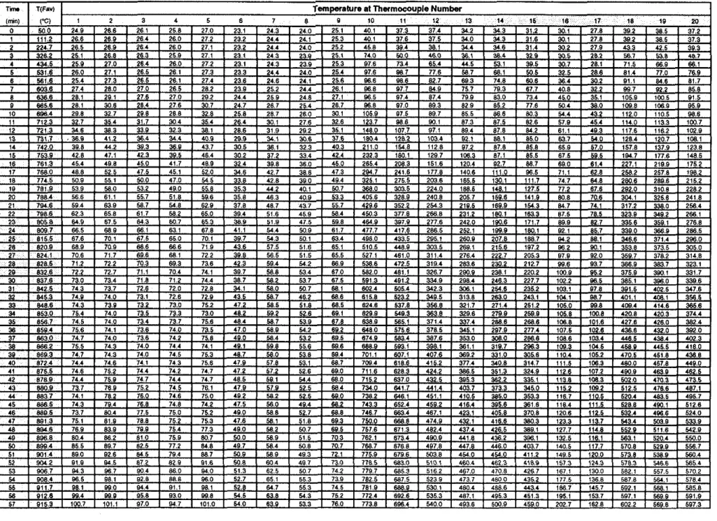
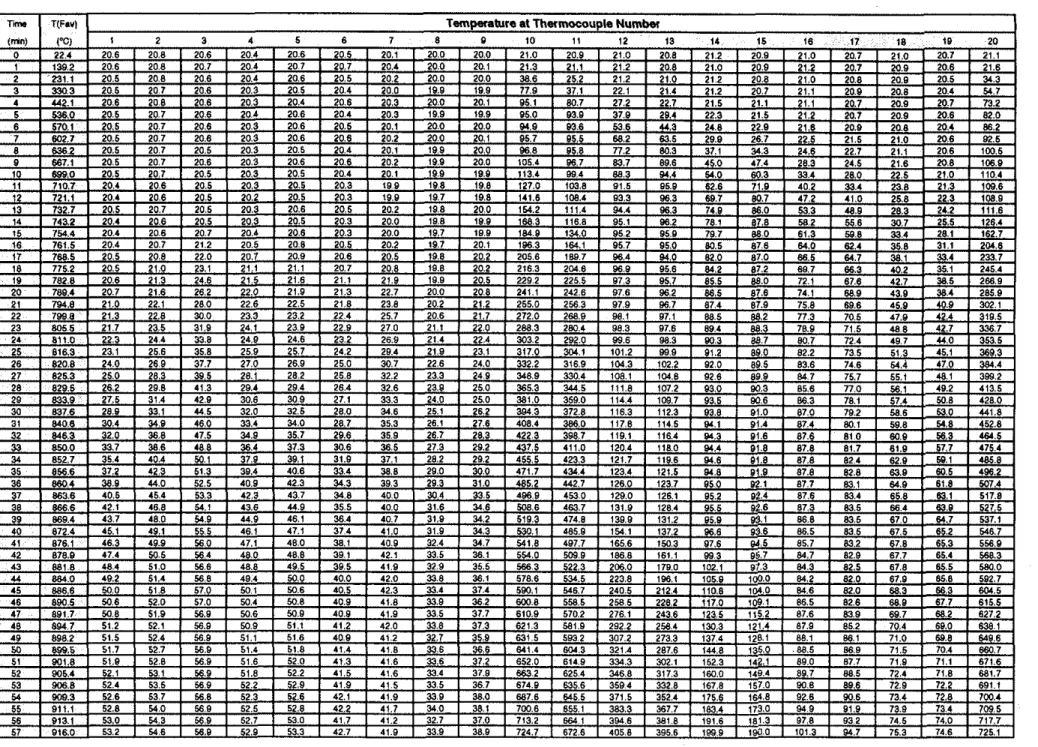
The furnace and wall assembly temperatures were recorded at 1 minute intervals.
Individual thermocouple values and average furnace temperature values as well as the average surface temperature values for the 21 assemblies are listed in Tables 1 to 42.
5.0 RESULTS AND DISCUSSION
The results of the 22 small-scale fire tests are summarized in Table 43 in which the
single point and average failure times are given for each assembly.
The average surface and inner-surface temperature distributions recorded throughout the tests are plotted in Figures 30 to 5 1. Detailed temperature distributions for all five thermocouples under the insulated pads on the unexposed surface are also plotted in Figures 30 to 50.
5.1 Fire performance of 1x1 (12.7 mm Thick Type X Gypsum Board) Insulated and Non-insulated SmaU-Scale Steel Stud Assemblies
The fire performance of the 1x1 insulated and non-insulated small-scale steel stud assemblies is shown in Figure 5 1.
Test S-09 (non-insulated) and Tests (insulated) S-22, S-14 and S-15 were camed out to investigate the effect of the installation of glass, mineral and cellulose fibre
insulation in a wall cavity on the fire performance of 1x1 assemblies. The temperature failure criterion was reached at 46 min for Test S-09 (non-insulated), at 46 min for
Test S-22 (glass fibre 90 mm thick), at 69 rnin for Test S-14 (mineral fibre 40 mm thick)
and at 69 min for Test S-15 (cellulose fibre 90 mrn thick). These results suggest that, in
small-scale 1x1, 12.7
mm thick Type X gypsum board assemblies, glass fibre insulation
has a neutral effect and both mineral and cellulose fibre insulations have a positive effect on the fire resistance performance compared to a non-insulated assembly.
5.2 Fire performance of 1x2 (12.7 mm Thick Type X Gypsum Board) Insulated and Non-insulated Small-Scale Steel Stud Assemblies
The fire performance of the 1x2 insulated and non-insulated small-scale steel stud assemblies is shown in Figure 52.
Test S-10 (non-insulated) and Tests S-23, S-26 and S-18 (insulated) were carried out to investigate the effects of the installation of glass, mineral and cellulose fibre insulation in the wall cavity. The temperature failure criterion was reached at 86 min for Test S-10 (non-insulated), at 88 min for Test S-23 (glass fibre insulation), at 114 min for Test S-26 (mineral fibre insulation) and at 134 min for Test S-18 (cellulose fibre
insulation). These results also suggest that, in small-scale 1x2, 12.7 mm thick Type X
gypsum board assemblies, glass fibre insulation has a neutral effect and both mineral and cellulose fibre insulations have a positive effect on the fire resistance performance compared to a non-insulated assembly.
5.3 F i e performance of 2x2 (12.7 mm Thick Type X Gypsum Board) Insulated and Non-insulated Small-Scale Steel Stud Assemblies
The fire performance of the 2x2 insulated and non-insulated small-scale steel stud assemblies is shown in Figure 53.
Test S-12 (non-insulated) and Tests S-25, S-27 and S-21 (insulated) were carried
out to investigate the effect of the 90 mm thick installation of glass, mineral and cellulose
fibre insulations in the wall cavity. The temperature failure criterion was reached at 129 min for Test S-12 (non-insulated), at 139 min for Test S-25 (glass fibre insulation), at 160 rnin for Test S-27 (mineral fibre insulation) and at 157 min for Test S-21 (cellulose fibre insulation). These results also suggest that, in small-scale 2x2, 12.7 mm thick Type X gypsum board assemblies, all insulations: glass, mineral and cellulose fibres have a positive effect on the fire resistance performance compared to a non-insulated assembly.
5.4 Fire performance of 1x2 (15.9 mm Thick Type X Gypsum Board) Insulated and Non-insulated Small-Scale Assemblies
The fire performance of the 1x2 insulated and non-insulated small-scale assemblies
using 15.9 mm thick Type X gypsum board is shown in Figure 54.
Test S-41 (non-insulated) and Tests S-42, S-43 and S-44 (insulated) were carried out to investigate the effects of the 90 mm thick installation of mineral, cellulose and glass fibre insulation in the wall cavity. The temperature failure criterion was reached at
136 min for Test S-41 (non-insulated), at 133 min for Test S-44 (glass fibre), at 135 min for Test S-42 (mineral fibre) and at 113 min for Test S-43 (cellulose fibre). These results
suggest that, in small-scale 1x2, 15.9
rnrn
thick Type X g sum board assemblies, both theglass and mineral fibre insulations have a neutral effect an
3'
cellulose fibre has a negative effect on fire resistance performance compared to a non-insulated assembly.5.5 Fire performance of 1x2 (12.7 mm Thick Type X Gypsum Board) Insulated with Cellulose Fibre (Blown Dry and Wet Spray) and Non-insulated Small- Scale Assemblies
The fire performance of 1x2 assemblies insulated with blown dry and wet spray cellulose fibre insulation on small-scale assemblies is shown in Figure 55.
Test S-I0 (non-insulated) and Tests S-18 (CFI, blown dry) and S-46 (CFI, wet spray) were carried out to investigate the effect of the application method (blown d ~ y or wet spray) for cellulose fibre insulation on the fire performance of 1x2 layer, 12.7 mm
thick Type X gypsum board, small-scale wall assemblies. The temperature failure criterion was reached at 86 min for Test S-10 (non-insulated), at 95 min for Test S-46 (cellulose fibre with wet spray application) and at 134 min for Test S- 18 (cellulose fibre with blown
dry application). These results suggest that in small-scale 1x2, 12.7 mrn thick Type X
gypsum board assemblies, both types of cellulose fibre insulation have a positive effect on the fire resistance performance compared to a non-insulated assembly. The assembly with blown dry insulation provided better fire resistance performance than the assembly with wet spray insulation. This suggests that the method of application for cellulose fibre insulation has an effect on the fire performance of small-scale assemblies.
5.6 Fire Performance of 1x2 (12.7 mm Thick Type X Gypsum Board) on Wood
and Steel Studs Insulated and Non-Insulated Small-Scale Assemblies
The fire performance of 1x2 layers on wood studs with resilient channels and steel
studs without resilient channels on insulated and non-insulated (12.7
mm thick gypsum
board) small-scale assemblies is shown in Figures 56 and 57.
Tests S-31, S-28, S-29 and S-30 (wood studs) and Tests S-10, S-23, S-26 and S-18 (steel studs) were carried out to investigate the effects of wood studs with resilient channels and steel studs without resilient channels on the fire performance of 1x2,
12.7
mm thick Type X gypsum board, small-scale wall assemblies. For wood studs with
resilient channels, the temperature failure criterion was reached at 96 min for Test S-3 1 (non-insulated), at 92 min for Test S-28 (glass fibre insulation), at 125 min for Test S-29 (mineral fibre insulation) and at 164 min for Test S-30 (cellulose fibre insulation). For steel studs without resilient channels, the temperature failure criterion was reached at 86 min for Test S-10 (non-insulated), at 98 min for Test S-23 (glass fibre insulation), at 114 min for Test S-26 (mineral fibre insulation) and at 134 min for Test S-18 (cellulose fibre insulation). These results suggest that, in insulated and non-insulated small-scale,
1x2 12.7 mm thick Type X gypsum board assemblies, the fire resistance performance of
assemblies with wood studs and resilient channels is slightly better than assemblies with steel studs.
REFERENCES
1. CANICSA-A82.27-M91, Gypsum Board-Building Materials and Products, Canadian Standard Association, Rexdale, Ontario, 199 1.
2. CANICGSB-7.1-M86, Cold Formed Steel Framing Components, CanadianGeneral -
Standards Board, Ottawa, Ontario, 1986.
3. CSA 0141-1970, Softwood Lumber. Canadian Standards Association. Rexdale. Ontario, 1970.
4. CSA-A101-M83, Thermal Insulation, Mineral Fibre for Buildings, Canadian Standards Association, Rexdale, Ontario, 1983.
5. CANICSA-A82.3 1 -M9 1, Gypsum Board Application, Canadian Standards Association, Rexdale, Ontario, 199 1.
6. List of Equipment and Materials, Vol. 3, Fire Resistance Ratings, Underwriters' Laboratories of Canada. Scarborough. Ontario. 199 1.
7 CANIIILC-S101-M89. Standard
ith hods
of Fire Endurance Tests of BuildingConstruction and Materials. Undcnvritcrs' Laboratorio of Canada, Scarborough, Ontario, 1989.
Table 2. Average Temperatures Measured in Assembly S-09, Steel Stud, 1x1 Gypsum Board Layers, No Insulation
Legend: BL
-
Base Layer. FL-
Face Layer, Cav.-
Cavity, SSld. - Steel Stud, Av - Average, Exp.-
Exposed Side, UnExp. - Unexposed SldeTable 6. Average Temperatures Measured in Assembly S-12, Steel Studs, 2x2 Gypsum Board Layers, No Insulation
Leaend: EL - Base Layer. FL
-
Face Laver. Cav. - Cavltv. SSM. -Steel Stud, Av - Average. Exo. - Exposed Slde, UnExo.-
Unsxwsed Side1- T(Far1 BUFL (EXPI B w s t a . (~xp.1 BVM. ~Exp.) utd. ssld. BUC.~ IU~EXP.) B U F W (UnEXp.) BmIUnExp.1 ~ n h p .
Table 12. Average Temperatures Measured in Assembly S-18, Steel Stud, 1x2 Gypsum Board Layers, Cellulosic Fibre Insulation (Cont) Laend: BL
-
B n a hvw. Cav.-
Cavlh. Std.-
Slud. Av-
A V O ~ W . Exo.-
Exwsul Slde. UnEm.-
Unexwsed SldeT m T(F.4 BVClv.(€nPJ Umald. (ulP$ U V C n . Nm.1 BMmO. (UnErp) BUK I W P 3 u ~ E X P .
I
YO 8elaI
(mn) pn rrcis.1e) w t a i r . u . s ~ A V ( I L I L ~ ~ ~ ) A~IXJ~I) Avl14,1hltre) AVI~CIT.Z~,ZS~~.~:)
Table 14. Average Temperatures Measured in Assembly S-21, Steel Stud, 2x2 Gypsum Board Layers, Cellulosic Fibre Insulation
Lagend: BL
-
B m Lava. C.V. -CavlW. Sld.-
Stud, Av-
Averwe. Ex@.-
Exweed Slda. UnExo.-
Unaxmsed Slda~m
(rrin)
a mN~EXO.)
Av(14,lSl T(FW -(-PI a m . ~ e x p ) WC~V.~UPJ ~ m s s m .
pC) Av(i0,1i,20,M.1131~ Av(1L1P.Sldll m a 3 1 LV(14~6,U.W
BUOUI~. ~ u n e r p . ~ B ~ ~ F L (unw.~ u n ~ x p AvtB,11,Y,%l A v i 1 8 , 1 P ~ l l , S , W Avlla,3.4,8l
Table 14. Average Temperatures Measured in Assembly S-21, Steel Stud, 2x2 Gypsum Board Layers, Cellulosic Fibre Insulation (Cont.)
Lwond: BL
-
B a u Lava. Cav.-
Cavllv. SM.-
Stud. AV-
Avoma. EXP.-
EXDO.& Sldo. UnEw. - UnoxW.ecl SldePm TIF.4 O f l L l ~ ~ . l BUSS(d. WP.) Bb-ViEXP.) M a E M M U E n . (UnEv.) IIVllOfd. (UnElP.1 W L (UnEX0.I UnElp
Table 18. Average Temperatures Measured in Assembly S-23, Steel Studs, 1x2 Gypsunl Board Layers, Glass Fibre Insulation Legend: BL
-
Base Layer, FL-
Face Layer, Cav. -Cavity, SStd. -Steel Stud, Av-
Average, Exp.-
Exposed Side, UnExp. - Unexposed SideTlma ,n.< T(ea#) PC. B J a v IEXP.) ArO2 231 B M S I a . (EIP I Av[l2,l3,l8,lBl HIaSSta. A v ( 1 0 ~ 1 , ? 6 1 7 l BuCa*. (JnExpl Av[24,2SI 8 M 6 1 0 . (UnElp.1 AY~l4lS20.211 9WL (UnEIp.) A108 19.32.33.36 37) UnE"p. Av11.23.4.9
Table 20. Average Temperatures Measured in Assembly S-25, Steel Stud, 2x2 Gypsum Board Layers, Glass Fibre Insulation (Cont.)
l g . LWW. FL
-
FaOb h V W . ClV.-
Cavltv. SSW.-
S l d Shld. AV-
Avmae. Em.-
E W M d Sid* UnEm.-
Unmx& SideI O mIExPl BVBWd (Em1 B m v . ~Eml H d . 8 s t ~ BVc.r.(un€.~.~ M B m IU~CXDJ 8 L J F L W P . I U n a p AV(III,??,M,Sl.YM W l l Z t S . 1 S . l ~ A V I ~ . ~ S I AV(1Pl t.lLt7l *yz4.25) A ~ ~ 4 , 1 5 2 0 , 2 1 )
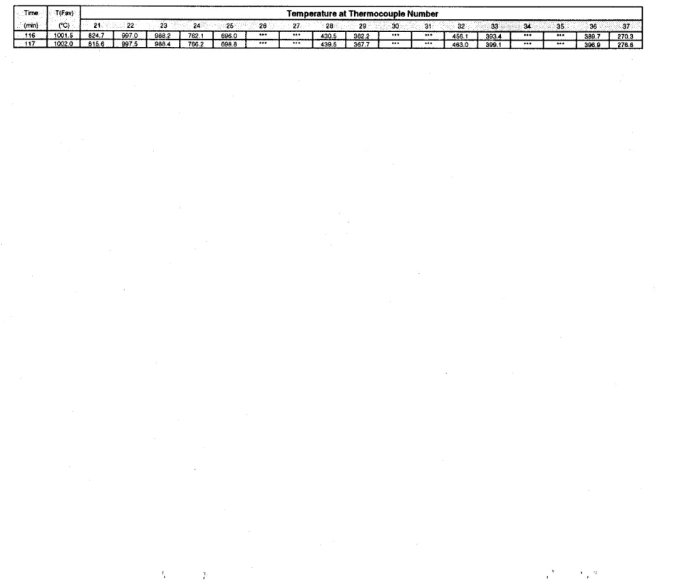
Table 21. Temperatures Measured in Assembly S-26, Steel Stud, 1x2 Gypsum Board Layers, Mineral Fibre Insulation (Cant.)
inn
lmn) 116 117
T(Far1 Temperature at Thermocouple Number
CCI 1 2 3 4 5 6 7 8 8 10 11 12 13 14 15 16 17 18 19 20
1W15 1 2492 1 1335 1 l W 7 1 1166 1 1850 1 9 0 5 1 6 7 8 1 6 7 7 1 636 1
...
...
...
1 9609 1 959 1 1 710 1 1 657 5 1 "' I...
1 8889 1 8541 1 5285 1W20 1 2660 1 1418 1 1102 1 1160 1 2017 1 9 4 8 1 6 7 5 1 6 8 9 1 6 3 7 1 "' I 1 9614 1 9780 1 7136 1 5611 1 "' I...
1 6 9 1 6 1 8 5 6 7 1 5 3 3 8Table 21. Temperatures Measured in Assembly S-26, Steel Stud, 1x2 Gypsum Board Layers, Mineral Fibre Insulation (Cont.) T8m lmn) 116
,
117 TlFav) 1%) 10015 i W 2 0Temperature at Thermocouple Number
21 22 23 24 25 26 27 28 29 30 31 32 33 ?4 35 36 37 8247 1 9 9 7 0 1 9 8 8 2 1 7 8 2 1 1 6 8 6 0 1 "' I
...
...
1 4 3 0 5 1 3 6 2 2 1 "' I...
...
1 4561 1 3934 1 "' I...
1 389 7 1 2703 8156 1 9975 1 9884 / 7662 1 6968 1...
I 1 4395 1 367 7 / "' I 1 4 6 3 0 1 3 9 9 1 1 "' I...
1 386 8 1 2766Table 22. Average Temperatures Measured in Assembly S-26, Steel Stud, 1x2 Gypsum Board Layers, Mineral Fibre Insulation
Lwand: BL
-
B m LLvu. F L-
Faca Lava. Cav.-
CevlIv. SSld.-
Stad Stud. Av - A v a a e . EM.-
E x m a d Slda, UnEm.-
Unaxwsed SideT r T(F.4
I
YYlmfdI
V-0)
.
m.
Ayl2.2s) A"(lZ13.la.10) A v l 1 Q 1 1 , l ~ , ~ 7 J AV12416) Avli4,16,ZO,ZlJ A"l2*a,a?,~*.al).- - - ... -- - - . .-. AW1,B 4,s)
-- -
Table 22. Average Temperatures Measured in Assembly S-26, Steel Stud, 1x2 Gypsum Board Layers, Mineral Fibre Insulation (Cont.) Lwend: EL
-
B m Laver. FL-
F r e Lava, Cav.-
CavIIv, SSM.-
S t d Stud, Av-
Avuaw, Ew.-
Exmwd Slda, UnEw.-
Unexwsd SldeT m T(For) 8Uc.V. (UlP.1 BMSId. (Ulp.1 MUOWE * U C . V . N W . 1 (IUBB~~. (UnEKp) OWL ( U M p . 1 UlftxP.
I
Table 24. Average Temperatures Measured in Assembly S-27, Steel Stud, 2x2 Gypsum Board Layers, Mineral Fibre Insulation (Cont.)
Leaend: BL
-
B a u hvu, FL-
Face Lav , Cav.-
Csvltv. SSkl.-
Steel Stud. Av-
uncle. Em.-
E m o w d Slde, UnExp.-
Unaxmwd Slder m T(F.UI OVRIE~PI B V ~ W 1-1 BIXW. tcmi tmWM. w . IMEXPJ m 8 ~ 1 u n - I BURIU~DP.) unero.
(mnt W ) Avts,zP,ao.ai,a4m ~ v l i a , i ~ , i e , ~ ~ ~~tn.sai AYIPII.ILI~ ~ ~ ( z r . 2 ~ ~~1r4,isaozii ~v~ab,m,s,s,man AVI~Z,S,*,S~
Table 24. Average Temperatures Measured in Assembly S-27, Steel Stud, 2x2 Gypsum Board Layers, Mineral Fibre Insulation (Cont.)
Table 28. Average Temperatures Measured in Assembly S-29, Wood Stud, 1x2 Gypsum Board Layers, Mineral Fibre Insulation Legend: EL
-
Bow Laver. FL - Faca Laver. Cav.-
Cavltv. Std. -Stud, Av-
Averaaa. Em.-
E x m r d Slda, UnEm.-
Unaxmed SldaT.mo T(F.r) e m . m.) m a . *.I utd md. B W . ( U n E ~ p l EuSm NnExp.) OWL (unW.1 Unw.
I
(mnl PC) AV.v(1b1@21.25) Av(tl.13) A ~ ~ ~ 1 1 , 1 4 . 1 6 ) 420,21,842Sl A~i18.17)
-. . . . ~ ~ ~- ~
r r i ~ 1 0 ~ a ? . s g s d 7 1
Table 28. Average Temperatures Measured in Assembly S-29, Wood Stud, 1x2 Gypsum Board Layers, Mineral Fibre Insulation (Cont.)
wend: BL
-
B m Lava. FL-
Face Lava. Cav.-
Cavlh. Std.-
Sad. Av-
Avaaae. Em.-
Exmnad Slde. UnExa-
UnexwMd Sldo1.m T~FW) O m . 1elD.l IW. (up.) wa ~ l d OuCav. (dnua) ~ ~ d m ( u n w . 1 DWL 1unW.1 unw.
I
I ~... IPC) w 1 h i o a z . n ) .-. - ~ y 1 2 . l a 1 -. - A~IO,II,~~,~SI . . - MZO.~I,Z~.WI Av(i(td.171 .-
-
Wl?b10a29S38.S71 -- * v t i . t a ~ . s ) ..Table 28. Average Temperatures Measured in Assembly S-29, Wood Stud, 1x2 Gypsum Board Layers, Mineral Fibre Insulation (Cont.) L ~ 8 n d : BL
-
E m Lav8r. FL-
Face Lava. Cav.-
Cavllv. Std.-
Shld. Av-
Avaaae. Ew.-
E x m u d Side, UnEm.-
Unexwabd SideTable 30. Average Temperatures Measured in Assembly S-30, Wood Stud, 1x2 Gypsum Board Layers, Cellulosic Fibre Insulation
Lwaend: BL
-
B g e Lava. FL - Face Laver, Cav.-
Cavltv, Std. -Stud. Av-
Avmaw. END.-
E X I X I ~ Slde, UnEm.-
UnsxDosed Sldw~ , m T(FW O m . 1E.p.I O WfCrp.1
I
ula ma 8 w . ( d n ~ r p ) .Mm (UnExp) f W...
... ... ... M10.¶1,Y4LR ... Avf1c4lj .. ~ A"l2LW829**,a7l ~.. Av11.2l.4A ~~ ~1
pQ b f 1 O l O l l W ) M 1 2 , l S I B W L W 4 . I AVf10,11,14,151 unw.Table 30. Average Temperatures Measured in Assembly S-30, Wood Stud, 1x2 Gypsum Board Layers, Cellulosic Fibre Insulation (Cont.) d: BL
-
BP. Lavu. FL-
F-8 Lavu. CPV.-
CavItV. Sld.-
Stud. AV-
Avoraaa Em.-
EXDW.d Side, UnEm.-
Unex- Sldes u w . (up.) m e . r n . ~ Ylem~. IW. (unerpl 8b'mE iUnE;v.I BLIFL i u n w . ) u n w .
l
~viie,toaa,a) ~ v ( t z . i a ) ~qto,ii,t4,1s) A W ~ , Z * , Z ~ ~ S I ~ v ( t ~ t t )
~~. .. . - . .. .. . A v l 1 4 8 a 2 , 9 4 W 1 ) .. . AVI~,*,~.~,W ~ ~
Table 30. Average Temperatures Measured in Assembly S-30, Wood Stud, 1x2 Gypsum Board Layers, Cellulosic Fibre Insulation (Cant.) Lmend: BL
-
Bass LJVY. FL-
F w e ~ Y W . Cav.-
Cavltv. Std.-
Stud, Av-
Avasae. Em.-
E m a d Slde, UnEm. - U n e x c a d Slde~ s r n T(FW BW. (L.P.) b m d . (Exp.1 ~d 8M. BUC.V. (U~EULI suna(unep.1 B U F L N ~ P . I U n P .
I
(mnl W ) AvllhlOa2.2B) AWIZ,I~)
~~ ~ ~~ ~
I
Table 32. Average Temperatures Measured in Assembly S-41, Steel Stud, 1x2 Gypsum Board Layers, No Insulation
Lwend: BL
-
B p . Laver. FL-
Face Laver. CIIV.-
CavlIv. SStd.-
St.* Slud. WStd.-
Wood Stlld. AV-
Avrane. EXV.-
EXDO~UI slde. UnEm.-
U n e x m d SldmT m T(FW I)UCn. l a p 1
I
(mnj WI
IMlld. (U*) nuaad ~ V C r . ( U ~ . ~
I
... A*2,2a) ~ ~~ q r ( t ~ l a . l a . 1 0 ) ~ ~ ( t o , ~ t . i a . t r j Av(2425l b(i4,th2o.m) ~q~s,?o.w,as,n.sq ~ v l t ~ z ~ a A . 5 1
Table 32. Average Temperatures Measured in Assembly S-41, Steel Stud, 1x2 Gypsum Board Layers, No Insulation (Cont.)
Leabnd: BL
-
B m L a w . FL -Fa- hvmr. Cav.-
Cavltv. SStd.-
Stwl Slud. WSM. -Wood Stud. Av-
Averme. E x a -Ex- Sldb. UnExD. - U n 8 x ~ o w d Sl& lm T I F ~ ) (mnl c-3 BUSStd Wp.1 IIVCn. W W . 1I
Uld 8-I
~ l 1 2 , 1 ~ , 1 8 , 1 0 l A r ( ~ ~ 1 l . 1 C l l l Avil42s) S v C n . (Cxp.) Art11.131 WSia WnEwl &vl14,16,M,10 OWL IUaPpJ M a p . Auflb,2@.8taS~%,Sl) A V l l J . ~ , ~ lTable 32. Average Temperatures Measured in Assembly S-41, Steel Stud, 1x2 Gypsum Board Layers, No Insulation (Cont.) Leaend: BL
-
B m L a v r , FL-
F a a Laver. Cav.-
Cavltv. SSld.-
%Slud. WSM. ..I-
Wood S M . Av - Avuma. E x r-
Exposad Slda. UnExo.-
Unexposad SldeWw TIFW (IW. (Up4 nw~d. mp.) Ym1)8(d (IVCIY.NIYID.1 8Mmd N n E l p ) (IUn ~ W P J MEW.
I
Table 34. Average Temperatures Measured in Assembly S-42, Steel Stud, 1x2 Gypsum Board Layers, Mineral Fibre Insulation
Leaend: BL - Base Laver. FL
-
Face Laver. Cav.-
Cavitv. SStd.-
S t d Stud. WStd.-
Wood Stud. Av-
Averma. Exa-
E x dSlde. UnExp.-
U n e x d SldeTW TIFW ImnJ WI I l u C w . ~ f a ~ l ~y)2.28) svema. w p . ] uniaw
I
M12l3.I1.101 ~vLr(i411,18.i71 OW*. N n m A*t?WSI nWBtd. (UnErpl AVll4,18lo.Il) B V h lUaCrpJ Av(t8.~.~,a3,25.3?) uaL.~. AWs2.%4.S1Table 34. Average Temperatures Measured in Assembly S-42, Steel Stud, 1x2 Gypsum Board Layers, Mineral Fibre Insulation (Cont.) Legend: BL
-
B a n Uvw. FL-
Face Laver. Cav.-
Cavlh. SStd.-
Strd Sbd, WSM,-
Wood Stud. Av-
Avwme, Exp. -Ex& Slda UnEm.-
Unwx& SldeT r T(F& IIuc.V.WP) o ~ w s t a . WPJ YD amd IIlh2.V. N W . l IIYOBtd.(Untw) IIl,7L I W P J W P .
Table 36. Average Temperatures Measured in Assembly S-43, Steel Stud, 1x2 Gypsum Board Layers, Cellulosic Fibre Insulation (Cont.) Laend: BL
-
B p . Laver. FL-
F o x b v a . Cav.-
Cavltv. SSW.-
S t d Stud. Av-
Avmae. EXD.-
Exrnwd Slde. UnEw.-
Unax- Slderm 1~F.r) WIXv. (CxPJ awaa. wp,) M!d a w l ~~. W m . 1 IIU8eta Nn€)rpl W L ( W P ) &Up.
Table 43. Small-Scale Assembly Parameters and Fire Test Results
X - Type X Gypsum Board (7.83 kg/&)
E
-
Exposed SideGF
-
Glass Fibre Insulation MF-
Mineral Fibre'lnsuiation CFI-
Celiulosic Fibre Insulation (Blown Dry) CFI - Celiulosic Fibre lns~lanon Wet Sprayed)Fire Exposed Side
Gypsum Boord Focing - II 17 18 90 mm steel studs--J
1sUnexposed Side
Omwing Not To S o l eFire Exposed Side
r
Gypsum Board Facing 90 mrn Steel Studsf
-. Unexposed SideDrawing Not To Scale
h-
am mrn-1
Figure 3. Thermocouple Locations in Small-Scale Test S-10
r
914 rnmI!
1
I II
I
I
I
I
I
I
I
I
I
I
I
I
12.1;:I
I
I
I
I
I
I
I
I
II
I
I
I
I
I
*I
I
I
I
I
1
1s.~;I
I
I
I
I
I
1
I
I
I
I
!
7
6 8 2 rnrn 2 3 2 r n m1
Fire Exposed Side
Steel StudsUnexposed Side
k
-
600 rnrn-4
I II
I
I
I
I
I
I
I
I
I
I
I
201
14.L:: nI
1
::
24 28I
I
I
914 rnrnI
I
I
I
I
I
I
I
I
I
I
I
I
I
I
682 rnrnI
1s. l 1.
::
1
::
n=.
I
I
l9 nI
I
I
I
I
I
I
Drawing Not To Scale
Fire Exposed Side
1
90 rnrn
f
ineral Fibre Insulation Unexposed Side
Drawing Not To Scale
i'
0 rnrn
Il
Figure 5. Thermocouple Locations in Small-Scale Test S-14
1
I
I
I
I
I
I
I
I
I
I
I
I
I
72.1;:
I
I
I
I
I
I
I
I
I
II
I
I
I
I
I
w * : iI
I
I
I
,I
I
'J*T::
0 : : 21I
I
I
I
I
I
1
I
I
-
I
!
I
I
675 rnrn 225 mrn1
Fire Exposed Side
r
Gypsum Board Facing90 rnrn
Steel Studs
f
Unexposed Side
Cellulosic Fibre lnsulotionDrawing Not To Scale
r1
914 mm
Ll
Figure 6. Thermocouple Locations in Small-Scale Test S-15
1 I
I
I
I
I
I
I
I
I
I
I
I
r*.L:,o
I
I
I
I
I
I
I
I
I
I
I
I
II
I
I
I
I
I
=-lz
I
I
I
I
I
I
13;;
I
I
I
I
I
1
1
I
I
-1;
I
-I
-:7
682 rnrn 232 rnrn(111
Fire Exposed Side
r
Gypsum Board Facing9 0 rnm Steel Studs
f
Side Cellulosic Fibre Insulation
Drawing Not To Scale
Fire Exposed Side
10
11 20 n m 2.
Steel Studs
19
Side
Cellulosic Fibre Insulationk-
600 rnrn ==-Drawing Not To Scale
Fire Exposed Side
Gypsum Boardr
FacingA
90 rnrn Steel Studs ,\
Side
Glass .%re Insulationp-
600 rnrn4
-Dmwing Not To Scale
Fire
Exposed Side Gypsum Board FacingI
.,. & . * . . 90 rnrn Steel studsJ
7d 7sE
a7Side
\_
Glass fibre lnsulatianp
-
6 W rnm-
j
457 rnrnb
-.
914 rnrn4
-Drawing Not To Scale
Fire Exposed Side
Gypsum Board Facing90 m m Steel Studs
Side
Glass Fibre InsulationDrawing Not To Scale
Fire Exposed Side
r
Gypsum Facing Board90 mm Steel Studs
f
Unexposed
Side
Mineral Fibre Insulationk-
600 rnrn---uf
Drawing Not To Scale
r
914 mrn
Ll
Figure 12. Thermocouple Locations in Small-Scale Test S-26
I 1
I
I
I
I
I
I
I
I
I
I
I
I
I
10.1;:l a
::
I
YI
I
I
I
I
I
I
II
I
I
I
I
I
le-;"I
I
I
I
I
11. 93I
12
.
Z1 '25 17.i?
YI
I
I
I
I
I
1
I
I
:
I
I
~7
682 rnrn 232 mrn!I
Steel Studs
Unexposed Side
Minerof Rbre Insulation90
Drawing Not To Scoie
Fire Exposed Side Gypsum Facing Board Resilient Channel
Gloss Fibre lnsulatio
Unexposed Side 1
- - -
-x---
,
-
57 rnm -T-Lr----
---
- - - - - ---
I
I
l
Raaiknt,,,
I
I
I1
I
18I
II
I I I
* w aaI I
I
I
I
II I
I I
914 mm Redlbnt mmmfI
I
I II
682 mrnII
I
Resilient haadI I
I
232 mm- - -
-I
I!
I:l.dmm
.
I
Drawing Not To Scale
Fire Exposed Side Gypsum Board Facing I Resilient Channel 7
1
,
89 mmMineral Fibre lnsulatio
f
Unexposed Side
914 mrn
457 mrn
Drawing Not To Scale
Gypsum Board
Fire Exposed Side Facing
I
Resilient Channel-
1
,
d
89 rnrn - --
-Cellulosic Fibre lnsulotion a0 s3 a7
Unexposed Side
I
I
I
1 1 -
f
II I
1sI II
II I
.
m wI I I
I I
II
I
I I
914 rnrntt---HI
I II
682 rnrn Rs~i6ant O m n dI
I
- - -
- - -
Ir--.dmrn-)
Drawing Not To Scale
Fire Exposed Side Gypsum Facing Board
1
Resilient Channel 71
,
Unexposed Side 400 rnrn--4
I
I
I l l
f
I I I
I II
3sI I I
I I
I I I
I I
Resilient ChancelI I
682 mrn 1s 457 rnrnI I I
-21I I I
Rasinmt awnnalI I
Drawing Not To Scale
Fire Exposed Side
P
9 0 mrn Steel Studs 211 9 .x a sa n Unexposed Side 682 mrn 232 rnm1
Drawing Not To Scale
Fire Exposed Side
r
Gypsum Boord Facing I 90 rnrn Steel Studsf
Side Mineral Fibre insulation
Drawing Not To Scale
h--
600 rnrn1
-Figure 19. Thermocouple Locations in Small-Scale Test S-42
r
4 rnrnL;
1 1~~I
I
I
I
I
I
I
I
I
I
I
I
I
90.1;:
z
1 . 1I
I
I
=
QI
I
I
I
I
I
I
1I
I
I
I
I
I
I
I
I
I
10 7aI
".Tg
i sI
.7s 33I
I
I
I
I
I
1
I
I
I
I
682 rr7
232 rnrn 457 mrn Q 914 rnrn"-:
!
I
Fire Exposed Side Gypsum Board
r
Facing 9 0 mm Steel Studsf
Side Cellulosic Fibre lnsulotion
I I
I
I
I
I
I
I
I
I
I
I
I
I
I
'0.1;:::
I
I"
3aI
I
I
914 mrnI
I
I
I
I
I
I
I
I
I
I
I
I
I
682 mm 7a.
YI
I
I
I
I
1
232 mmI
I
Drawing Not To Scale
Fire Exposed Side
r
Gypsum Board Facing IA
90 mm Steel Studs .-
3
23 38 wf
b=-
600 rnm-
1
7
232 rnrnDrawing Not To Scole
Fire Exposed Side
Gypsum Boardr
Facing r : '.,
' 4 . ,.
33. A .-
.21':.. .- -;:.
Steel Studs.Side
\-Cellulosic Fibre Insulationp
-
600 rnrn1
-914 rnrn
b
-
914 mrn4
-Drawing Not To Scale
Fire Exposed Side Gypsum Board
r
Facing I4
9 0 rnrn Unexposed Sidef
Cellulosic Fibre Insulation
k-
600 rnrn1
-9 1 4 rnm
b
457 rnrn 682 rnrn 232 rnm1
-
9 1 4 mrn4
-Drawing Not To Scale
LL
Resilient ChannelGypsum Board
32 mm Philips Head Screw
Edge View: Resilient Channel
Drawing not to scale
Fire Exposed Side
4
400 rnrnBase Loyer
W
W
Face Layer Unexposed Side
(a) Base Layer (a) Base Layer
Gypsum Board Joint
-=-/ 400 rnrn
-=-/
400 rnrn 914 rnrn I 400 rnrnI
400 rnrnb
L,
(b) Face Layer 914 rnrn-4
(i) Fire Exposed Side
(ii)
Unexposed SideDrawing not to scale
Figure 25. Screw Locations For Wood Stud, 1x2 Gypsum Layers, Small-Scale Assemblies S-28, S-29, S-30 and S-31
Fire Exposed Side 600 mm
~ p - 4
Unexposed Side--PI
6 0 0 m m 600 mm 914 rnm Gypsum Board Joint 914 rnrn----4
Gypsum Board Joint. .
(i) Fire Exposed Side (ii) Unexposed Side
Drawing not to scale
Figure 26. Screw Locations For Steel Stud, 1x1 Gypsum Layers,
Fire Exposed Side
600 rnrn
---+
Ic
IC
Base Layer-
Face Layer
/d
Unexposed Side(a) Base Layer (a) Base Layer
4
600 rnrn4
600 rnrn1'
,I1
' 1
600 mrn Gypsum Board Joint}-
91 4 rnrn---4
7
600 rnrn&
9 1 4 rnrn-4
(b) Face Loyer 600 rnrn\---
Gypsum Board Joint(i) Fire Exposed Side
(ii)
Unexposed SideDrowing not to scole
Figure 27. Screw Locations For Wood Stud, 1x2 Gypsum Layers, Small-Scale Assemblies S-10, S-18, S-23, S-26, S-41, S-42, S-43, S-44, S-46 and S-47
Fire Exposed Side
600 mm
1
Base Layer
Face Layer
/d
Unexposed Side(a) Base Layer (a) Base Layer
*
600 rnm4
600 mm (b) Face Layer-4
600 mm 600 rnm 914 rnm 600 mrn Gypsum Board Joint (b) Face Layer +=/ 600 m m1-
914 rnm4
914 rnm4
300 mrn(i)
Fire Exposed Side(ii)
Unexposed SideDrawing not to scale
Figure 28. Screw Locations For Steel Stud, 2x2 Gypsum Layers, Small-Scale Assemblies 5-12, S-21, S-25 and S-27
rn
Thermocouple Under Std.
ULC/S101
Insulated
Padx
Bare Thermocouple
Drawing not to scale
Figure 29. Thermocouple Locations on Unexposed Surface Small-Scale Tests
0
0 20 40 60 80
Time (min.)
-
I I I(a) Average Face Temperature Distribution Average Values
-
-
- ULC Furnace Temp. -
. - - BUSStd. (Exp.) .--.. BUCav. (Exp.)
-
- Mid SStd. - - .. .. ... BUSStd. (UnExp.) - BUCav. (UnExp.1 ..-.- UnExp.-
Failure Criterion 1-
_._____._.-._.___--- (Rm. Temp. + 139'C)1
I(b) Unexposed Temperature Distribution Uneqosed Face
Failure Criterion 2
(Rm. Temp. + 180'C)
0
0 20 40 60 80
Time (min.)
1 ' 1 1 1 " ' 1 ' 1 1 1 " 1 1 1 " 1 " 1
-
(a) Average Face Temperature Distribution Average Values
-
-- ULC Furnace Temp.
-
-
- - - BUCav. (Exp.) ... BUSStd. (Exp.)-
- Mid. SStd. . . ... .... BUCav. (UnExp.) - BUSStd. (UnExp.)-
..-.- BUFL (UnExp.) --
UnExp. Failure Criterion I - (Rm. Temp. + 139'C) - 1 1 1 1 1 1 1 1 1 1 1 1 1 1 1 1 1 1 1 1 1 1 1 1 0 0 20 40 60 80 1 00 120 140 Time (min.) 0 0 20 40 60 80 100 120 1 40 Time (min.) 1 " ' 1 " ' 1 ' " 1 " ' 1 " ' 1 " '(b) Unexposed Temperature Distribution Unexpased Face -Thermocouple 1 - - - Thermocouple 2