Assessment of a Precast Prestressed Segmental Concrete
Rail Transit Guideway Design
by
H6ctor J. Cruzado
B.S. Civil Engineering (1996) University of Puerto Rico
Submitted to the Department of Civil and Environmental
Engineering in partial fulfillment of the requirements for
the degree of
Master of Science in
Civil and Environmental Engineering
at the
MASSACHUSETTS INSTITUTE OF TECHNOLOGY
June 1998
@ Massachusetts Institute of Technology, 1998. All Rights Reserved.
A uthor ...
. ...
... .... .. .. . ...
Depairoent of Civil
d Environmental Engineering
May 8, 1998
Certified by ...
... ... ...Y
Jerome J. Connor
Professor of Civil and Environmental Engineering
Thesis Supervisor
Accepted by ...
Joseph M. Sussman
Chairman, Department Committee on Graduate Students
Assessment of a Precast Prestressed Segmental Concrete
Rail Transit Guideway Design
by
H6ctor J. Cruzado
Submitted to the Department of Civil and Environmental Engineering on May 8, 1998, in partial fulfillment of the requirements for the degree
of Masters of Science in Civil and Environmental Engineering
Abstract
The four objectives of bridge design (safety, serviceability, economy, and aesthetics) are discussed, and their complex interrelation is analyzed using, as a background, a precast prestressed segmental concrete rail transit guideway being constructed as part of the Tren Urbano Project in Puerto Rico. Advantages and problems with this type of structure are discussed. Special attention is given to problems related to bearings and expansion joints. To observe the effects that a design decision would have on the four objectives, a bridge model is developed and analyzed using the program SAP2000 in which the continuity of the superstructure is given different configurations. The changes of the structural behavior with changes in continuity are evaluated under dead loads, live loads, earthquake loads, creep, shrinkage, and thermal effects. A life-cycle cost analysis is executed to observe the economical impact of changing continuity. Suggestions on how to evaluate a design deci-sion while considering the four objectives are made.
Thesis Supervisor: Jerome J. Connor
Acknowledgments
First and foremost, I would like to thank my advisors, Ken Kruckemeyer and Professor Connor, without whose advise I would not have been able to undertake this difficult research project. Their encouragement and support helped me do more than I could have imagined.
My good friend Salvatore Di Bernardo never got tired of me asking him so many ques-tions. He acted as my 24-hours-a-day advisor.
I made many friends in M.I.T., but there is nothing like the friendship given to me by Mia Lindsey, Patricia Llana, Jerry King, Adrian LeBuffe, and Mark Chow. Without them, I probably wouldn't have lasted this long in here.
I had two great roommates when I was an undergrad in Puerto Rico, and I never thought I would ever find roommates like that again. I was so wrong! My roommates at M.I.T., Carlos Gallegos and Gilberto Mosqueda, are now like family to me. Many thanks also to my undergrad roommates, Pepin Torres and Miguel Rullin, for always supporting me.
I would also like to thank Daniel Zarrilli, O. P. Agarwal, and Emma Shepherdson, who gave me their help without asking for anything in return.
Of course, the members of my family have always been my biggest fans. I have to thank my dad, for giving me that Flash Gordon comic book more than fifteen years ago and for renting those Clint Eastwood movies for me, and to my mom, who always made sure I had everything I needed. I send my love to my three sisters and my two grandmas, and I wish so much that my grandpa Hector was still alive to see this.
Thanks to my godparent for giving me a second family, and to my two best friends in the world, Luicho and Picu, for sticking with me through good and bad times.
Finally, I would like to thank all those great professors I had in the University of Puerto Rico. Especially Luis Suirez, Mario Rivera Borrero, Leandro Rodriguez, Gerson Beauchamp, Antonio GonzAlez, and Juan Bernal. Their dedication to teaching took me to where I am today.
Table of Contents
1 Introduction ... 15
1.1 Bridge and Elevated Guideway Design ... ... 15
1.2 The Tren Urbano Project ... 17
1.3 Bridges in Puerto Rico ... 17
1.4 Research Objectives... ... 19
1.5 O rganization... ... 20
2 Precast Prestressed Segmental Concrete Bridges and Guideways ... 22
2.1 Reinforced vs. Prestressed Concrete ... ... 23
2.2 Non-Segmental Prestressing vs. Segmental Prestressing ... 25
2.3 Precast vs. Cast-In-Place... ... 26
2.4 Precast Prestressed Segmental Concrete Construction ... 27
2.4.1 Fabrication of the Precast Segments ... .... 28
2.4.2 Erection Methods ... 30
2.4.3 Joints ... ... 32
2.4.4 Railroad Bridges and Guideways... ... 33
3 Design Considerations for Precast Prestressed Segmental Concrete Bridges and G uidew ays... ... ... 37 3.1 Introduction ... ... 37 3.2 Design Objectives ... ... 37 3.2.1 Safety ... ... 37 3.2.2 Serviceability ... ... ... ... 39 3.2.3 Economy ... ... 40 3.2.4 A esthetics ... ... 41
3.3 Major Issues in the Design of Precast Prestressed Segmental Concrete Bridges and Guideways ... ... 43
3.3.1 Continuity ... ... ... 43
3.3.2 Expansion Joints ... 48
3.3.3 B earings ... ... 51
3.3.4 Fabrication of the Precast Segments ... .... 54
3.3.5 Joints ... ... 55
3.3.6 Ducts, Prestressing Tendons, and Anchors...57
3.3.7 Erection Methods ... 59
3.3.8 Instabilities ... ... ... 59
3.3.9 Geometric Control ... 60
3.3.10 Time Dependent Effects ... 60
3.3.11 Superstructure/Rail Interaction ... ... 61
4 Tren Urbano Rail Transit Guideway Design ... 63
4.1 The Bayam6n Contract ... 63
4.2 D esign ... . ... 63
4.3 Methods of Erection... ... 67
4.4 Loads and Forces ... ... 71
4.5 Possible Sources of Problems ... ... 78
5.1 Improvements Through Continuity... ... 81
5.2 SA P2000 ... ... 82
5.3 Description of Models... ... 83
5.3.1 Model for Analysis of Dead Loads, Live Loads, and Seismic Loads ... ... ... 83
5.3.2 Model for Analysis of Creep, Shrinkage, and Thermal Effects...87
5.4 M odeling of Loads ... ... ... 90
5.4.1 Dead Loads ... 91
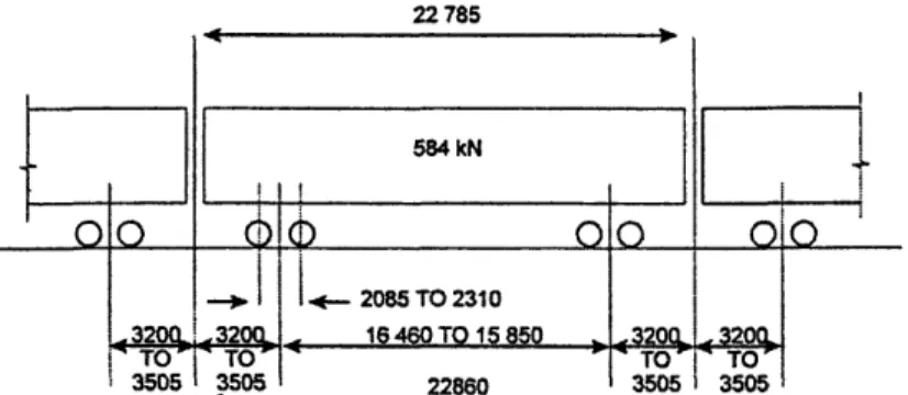
5.4.2 Live Loads ... 92
5.4.3 Earthquake Loads...93
5.4.4 Creep and Shrinkage ... ... 94
5.4.5 Temperature Effects... 95
5.5 A nalysis Process ... ...96
5.6 R esults ... ... 97
6 Life-Cycle Costing... 103
6.1 Bridge Economy ... ... ... 103
6.2 Effects of Increasing Continuity on the Life Cycle Cost of a Bridge... 105
6.3 Life-Cycle Cost Analysis ... 106
6.4 Results... ... 109
7 Increasing Continuity of Tren Urbano ... 113
7.1 Introduction ... 113 7.2 Safety ... 113 7.3 Serviceability ... 114 7.4 Economy ... 116 7.5 Aesthetics ... 117 7.6 Conclusions ... ... 118
Appendix A Input Files for Dead Loads, Live Loads, and Earthquake Loads ... 123
A .1 Sim ple Span Design... ... 123
A.2 Two-Span-Continuous Design... ... 133
A.3 Three-Span-Continuous Design... ... 141
A.4 Four-Span-Continuous Design... ... 148
Appendix B Input Files for Creep, Shrinkage, and Thermal Effects ... 155
B.1 Simple Span Design ... 155
B.2 Two-Span-Continuous Design... ... 167
B.3 Three-Span-Continuous Design... o ... ... 175
B.4 Four-Span-Continuous Design ... ... 186
Appendix C Elastomeric Bearings Properties ... ... 195
Appendix D Column Design ... ... 199
Appendix E Spread Footing Design ... 203
Appendix F Pier Segments Cross-Sections ... ... 213
Appendix G Stresses in the Rail ... 217
List of Figures
Figure 1.1: Construction of a precast segmental concrete bridge... 16
Figure 2.1: The long-line method ... 29
Figure 2.2: The short-line method ... 29
Figure 4.1: Elevation of column with pier cap ... ... 65
Figure 4.2: Reinforced elastomeric bearing. ... 66
Figure 4.3: Expansion joint... ... 67
Figure 4.4: Span-by-span method ... 69
Figure 4.5: Balanced cantilever method ... ... 70
Figure 4.6: R ail vehicle... ... 72
Figure 5.1 :Model of two-span-continuous design for dead loads, live loads, and earthquake loads ... ... ... 84
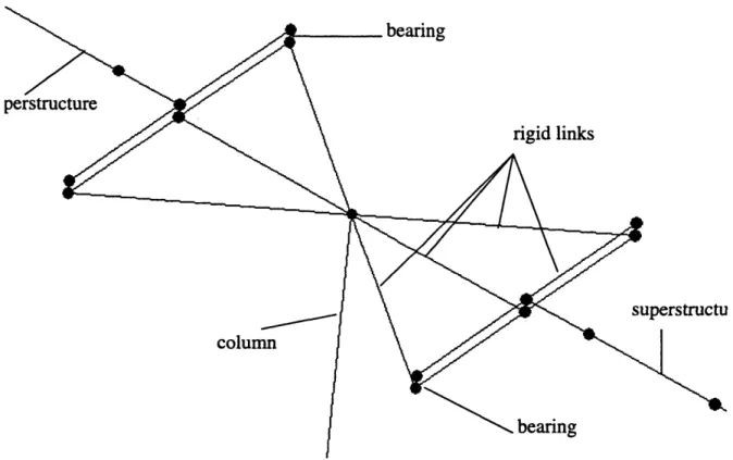
Figure 5.2: Expansion column model ... 85
Figure 5.3: Model of two-span-continuous design for creep, shrinkage, and temperature ef-fects ... ... ... 87
Figure 5.4: Idealization of the rail/superstructure interaction...88
Figure 5.5: Modeling of the rail/superstructure interaction using SAP2000 ... 88
Figure 5.6: Equivalent loads for prestressing ... ... 92
Figure 5.7: Response spectrum ... 94
Figure 6.1: Sensitivity analysis for operating costs ... 110
Figure 6.2: Sensitivity analysis for life-cycle cost... 111
Figure 7.1: Interrelationship of the four objectives based on issues of continuity for a pre-cast prestressed segmental rail transit bridge structure supported on spread foot-ing ... ... ... 120
Figure D. 1: Example of column interaction diagram ... .. 201
Figure E. 1: Spread footing dimensions... 204
Figure E.2: Pressure distribution for e/IL > 1/6, and ea/B > 1/6 ... 205
Figure E.3: Pressure distribution for e/L < 0.5, and 0 < eB/B <1/6 ... 209
Figure E.4: Pressure distribution for er/L < 1/6, and 0 < es/B < 0.5 ... 210
Figure E.5: Determination of maximum pressure... 211
Figure F. 1: Expansion segment, cross-section one ... .... 213
Figure F.2: Expansion segment, cross-section two... .... 214
Figure F.3: Pier segm ent ... ... 215
List of Tables
Table 5.1: Bearing dimensions ... 98
Table 5.2: Maximum loads in the superstructure due to creep, shrinkage, and tem perature ... ... 99
Table 5.3: Maximum stresses in the rail ... 99
Table 5.4: Applied prestressing load ... 100
Table 5.5: Gross reinforcing ratio of the columns ... 100
Table 5.6: Spread footing dimensions of width and length ... 101
Table 6.1: U nit costs ... ... 106
Table 6.2: Detailed construction costs ... 109
Table 6.3: Total construction costs ... 109
Chapter 1
Introduction
1.1 Bridge and Elevated Guideway Design
An elevated guideway is a structure that is similar to a bridge. The difference between these two structures has not been clearly established, but normally an elevated guideway is a longer structure that is not used for crossing over an specific obstacle, like a river or a canyon. Instead, it crosses a city, over previously built streets and other structures. In any case, in engineering terms, both the bridge and the elevated guideway are the same structure. The structural engineering terms that apply to one also applies to the other. Therefore, when referring to all bridge-like structures including elevated guideways and viaducts, only the word bridge is used. The same terminology has, therefore, been used in this report as well.
Designing a bridge structure or an elevated guideway is a very complex task. Its fun-damental objectives are safety, serviceability, economy, and elegance (Menn, 1990). The
final design depends on the relative weight given to each of these objectives.
Progress in the field of structural analysis includes innovations in computer analysis and a greater understanding of the behavior of structures. This has caused an increase in the demand for structures that require less maintenance, make optimal use of space, and behave better when subjected to lateral loads such as earthquakes and wind loads. Therefore, it has become very important to have an understanding of what it means to accomplish the above mentioned objectives. It is also very important to learn the complex relationship that exists between the four objectives.
There are a great number of decisions that need to be made in order to make a bridge design that fulfills all the desired objectives. Probably, one of the first decisions to be taken is what type of bridge will be used. One of the options that a bridge designer has is the Pre-cast Prestressed Segmental Concrete bridge. This type of construction is specially appropri-ate when one or more of the following conditions are met:
1. There is a need for longer spans than the ones that can be built using other simpler con-struction methods.
2. The bridge has to pass over an area where a critical requirement is for the construction of the superstructure to be done from the top of the piers. Examples of such require-ments are when a bridge has to be built over a canyon or across an urban area, where traffic cannot be obstructed.
3. The bridge has a large number of repetitive spans.
In the concrete segmental construction of bridges, the bridge is composed of several elements called segments. These segments can be either precast or cast-in-place. They are held together and made to carry loads by post-tensioning. The advantages of this construc-tion method (discussed in Chapter 2) have made segmental construcconstruc-tion very popular today. Like any other type of bridge construction method, the relationship between the four design objectives is a very complex one that needs to be understood.
1.2 The Tren Urbano Project
The Tren Urbano is a rapid transit system being designed and built for the metropol-itan area of San Juan, Puerto Rico. The system includes elevated, underground and ground-level rail transit sections.
The first section of the Tren Urbano Project is known as the Bayam6n contract. It is currently under construction and is scheduled to be finished by September of 1999. It con-sists of an elevated railway of 2.9 km length.
The elevated railway design of the Bayam6n phase is composed mostly of two-span-continuous units, formed by precast box segments, seated in epoxy, and held together by prestressing steel cables. At the beginning and at the end of each unit, expansion joints and elastomeric bearings are used.
The design of the Bayam6n phase will be covered in more detail in Chapter 4. Before covering the design in detail, it is important to know the past history of bridges in Puerto Rico, so that likely problems can be anticipated.
1.3 Bridges in Puerto Rico
When posed with the question: "What is the major source of problems with bridges in Puerto Rico?", most bridge experts would probably answer: "expansion joints".
This is not a problem that is unique to Puerto Rico. Expansion joints are a source of problems for bridges around the world. If there are problems with the sealing system of the joint, leaks can occur. Therefore, there can be corrosion in the reinforcement steel and in the
bearing system, and stains noticeable on the columns. Protection against corrosion is very important in Puerto Rico, given that it is an island and has a lot of salt in the air. Without enough cover, reinforcement steel quickly corrodes.
Another problem typical in Puerto Rico is that the expansion joints themselves dete-riorate. This deterioration can be felt by a rider in a moving vehicle as a bump. How uncom-fortable and noisy the bump is will depend on how deteriorated is the expansion joint. The deterioration will also cause stresses that were not accounted for in the guideway design.
The causes of problems with expansion joints are: improper installation and poor inspection and maintenance. It is generally believed in Puerto Rico that if expansion joints were properly installed and given reasonable inspection and maintenance, there would be no problems with them on the island.
Usually, the highest loads for which bridges in Puerto Rico are designed are earth-quake loads. Although there has not been an earthearth-quake in Puerto Rico since 1918, the island is located in an earthquake prone zone. Recent events in California and Japan make designing for earthquakes a field that is increasing in importance and sophistication.
Another fact is that bridges in Puerto Rico are mostly built using simple spans. Very seldom do designers try to take advantage of using continuous units. They seem to be extremely cautious about changes in length due to changes in temperature, which is very strange because the temperature in the Puerto Rico does not goes through such drastic changes as it does in other parts of the world. It also appears that not many designers are willing to go through the more complicated procedure of designing for continuous spans.
Segmental bridge construction is practically new in Puerto Rico. Only one segmen-tal concrete bridge has been constructed: the Caguana River Bridge in Utuado, a part of
Highway 10. There are no segmental elevated railways in Puerto Rico. In fact, there are no railway bridges in operation in Puerto Rico.
1.4 Research Objectives
The objectives of this research are:
a) Improve upon the current design philosophy for the elevated railway structure of the first phase of the Tren Urbano Project with the hope that these improvements are considered for adoption in the design of future sections of the project and in future designs similar to the one presented here. This objective will be achieved by analyzing how the behavior of the structure would be affected by changes in span continuity (simple span, two-span-continu-ous, three-span continutwo-span-continu-ous, etc.). Alternative designs might have the following advantages over the current design:
1. Less vibrations. 2. Smallerodeflections. 3. More stability.
4. Greater resistance and better behavior under lateral loads, particularly earthquakes.
5. Use of fewer expansion joints and bearings, which in turn would mean a structure that needs less maintenance.
6. Improved appearance.
b) Study the feasibility and economic impact of the alternative designs. Once an optimal design is found, it needs to be determined as to what is needed to be done to make the changes and what are the costs associated with these changes. The cost-effectiveness of making the changes, as compared to keeping the current design, will be studied by
perform-ing a life-cycle cost analysis. This will determine the plausibility of makperform-ing the improve-ments to the design.
1.5 Organization
In Chapter 2, the precast prestressed segmental concrete construction method is introduced, presenting advantages and disadvantages that this method will have in compari-son with other methods. A general overview on the process of design and construction of precast prestressed segmental concrete bridges and guideways is given.
In Chapter 3, the four design objectives (safety, serviceability, economy, and aes-thetics) of bridge structures are discussed. Design issues that may cause the failure of not achieving the four objectives when constructing the precast prestressed segmental concrete bridges or guideways are presented.
In Chapter 4, the design of the first phase of the Tren Urbano is presented in detail. The method of construction is also explained. Possible problems that may arise with the structure are mentioned.
In Chapter 5, an analysis is performed in order to study the structural impact of increasing changing the continuity of a bridge structure similar to that of the Tren Urbano Project. An introduction to the computer program SAP2000 is given. The results obtained from the analysis using the program are discussed.
In Chapter 6, a Life-Cycle Cost analysis is performed on each of the design alterna-tives evaluated in Chapter 5.
Finally, in Chapter 7, the results of the analysis presented in Chapter 5 and 6 are ana-lyzed to show how the four fundamental objectives of bridge design get affected with one design decision, in this case being increasing continuity of the superstructure. Final recom-mendations are given on how to improve the design philosophy in the design of bridges.
Chapter 2
Precast Prestressed Segmental Concrete Bridges
and Guideways
2.1 Reinforced vs. Prestressed Concrete
Prestressed concrete is defined by the American Concrete Institute (ACI) as: "con-crete in which there have been introduced internal stresses of such magnitude and distribu-tion that the stresses resulting from given external loadings are counteracted to a desired degree. In reinforced-concrete members, the prestress is commonly introduced by tension-ing the steel reinforcement."
It is known that concrete performs well under compression, but it is not as good under tension. When prestressed concrete was invented, it was with the idea of achieving a concrete that did not have any tensile stresses when external loads were applied. As the def-inition of the ACI says, the prestressing was done by tensioning the reinforcement steel of the concrete members.
In reinforced concrete, the tensile forces resulting from the bending moments are resisted by the reinforcing steel, which is put into tension by the bond created in the forcement process. Therefore it is assumed that the tensile strength of the concrete in rein-forced concrete is negligible and disregarded. Once a reinrein-forced member reaches its limit state at service load, the cracking and deflection that occur are practically irrecoverable.
In contrast, in prestressed concrete, the prestressing permits a relatively high trolled recovery of cracking and deflection. In the case the flexural tensile strength of con-crete is exceeded, the prestressed member starts to act like a reinforced concon-crete element.
There are certain qualities of prestressed concrete that can make its use more cost-effective than the use of reinforced concrete. A prestressed member usually has a depth of about 65 to 80 percent of the depth of a reinforced concrete member with the same span and loading conditions (Nawy, 1996). This means that there is a saving in materials when pre-stressed concrete is used. Also, by having shallower depths, the prestressing members can be lighter than the reinforced members, which means that lighter foundations can be achieved with prestressed members. In addition, because cracking is reduced, less mainte-nance is needed and longer working life can be achieved using prestressed members, again meaning more savings.
By no means do the statements above imply that prestressed concrete its always more economical than reinforced concrete. In prestressing, a higher quality of materials is needed. Besides, performing the prestressing is a more complex task than simply reinforc-ing the concrete, therefore resultreinforc-ing in an additional cost. Which one is more economical between prestressed or reinforced concrete depends on the specifics of the structure being designed.
When a beam is being designed for a span longer than 30 meters (like the ones used in bridges and guideways), if reinforced concrete is used, the cross-section needed to resist the moments caused by the life loads will be very large. This increases the self-weight of the beam substantially, causing excessive cracking and deflections. Therefore, the use of pre-stressed concrete becomes necessary, unless arches are used.
2.2 Non-Segmental Prestressing vs. Segmental Prestressing
Currently, short-span bridges (up to 50 meters) in the United States are most com-monly build using precast pretensioned concrete I-girders, taking advantage of all the bene-fits of using prestressed concrete (PCI, 1992). Still, although longer spans can be achieved with prestressed concrete than with reinforced concrete, sometimes there were requirements for even longer spans that could not be achieved with just prestressed concrete. Other mate-rials, like steel, had to be used. Therefore, segmental construction got its start as an alterna-tive concept for bridging longer spans.
Segmental bridges are those that are constructed from a number of short transverse segments. Usually, prestressing is applied to segmental bridge construction, allowing the construction of longer and/or thinner spans. Prestressing is done by using post-tensioning tendons in the longitudinal direction of the beams.
The most typical configuration in prestressed segmental bridge construction is the box girder. This is true because in most cases, box girders are the most efficient and eco-nomical design for a bridge (Podolny and Muller, 1982). In fact, the box girder has been used in almost every type of bridge construction including simple span, continuous spans, cantilevers, arches, stayed girders, and suspension. When using box girders, permanent post-tensioning can also be applied transversely to the top slab to increase the strength of the deck, and vertically to the webs to increase the shear capacity of the box girder.
The box girders used are mostly single cell and double cell. There have been cases where three-cell box girders has been used, but these segments need temporary stiffeners to prevent buckling during construction (Wium and Buyukozturk, 1984).
Since getting started as an alternative to bridging longer spans, segmental construc-tion continued development because it offers other advantages. One of them is that horizon-tally curved alignments, humps or sag vertical curves, and transitioned cross slopes can easily be accommodated with segmental construction. Also, when compared to other types of construction, segmental prestressed construction can be done by a small work force per-forming repetitive tasks. Besides, with segmental construction it is possible to reduce signif-icantly the interference with existing traffic, eliminating expensive detours.
Finally, it is normally believe that segmental construction protects the environment (Podolny and Muller, 1982). If an elevated guideway is constructed instead of constructing a highway, a road, or a railway using cut-and-fill type of construction, then an environmen-tally sensitive area would be less affected with the narrower path of the alignment construc-tion. Then, if the guideway was constructed using segmental construction, longer spans would be possible and the construction of the superstructure could be done from top of the piers, thereby protecting the environment even more.
2.3 Precast vs. Cast-In-Place
As mentioned before, segmental bridges are constructed from a number of short transverse segments. The segments can be either:
1. Precast, meaning they are manufactured in a precast yard on or off-site, which then are taken to the bridge location where they are assembled; or
2. Cast-In-Place, meaning they are cast in their final position.
Choosing between any of the two will bring advantages and disadvantages.
The advantages of the using precast concrete over cast-in-place concrete in pre-stressed segmental bridge construction are:
1. The precast segments can be fabricated while the substructure is being built, which means a saving in construction time.
2. The fabrication of this segments is done by the repetitive use of industrialized manufac-turing techniques. This provides the opportunity of achieving high quality and high strength concrete.
3. There is no need for falsework and everything can be accomplished from the top of the completed portions of the structure. This is very useful when traffic has to remain undis-turbed under the bridge or for high-level crossings.
4. The effects of shrinkage and creep are substantially reduced. This happens because usu-ally, the segments have already matured to full design strength by the time of erection and post-tensioning.
5. Precast construction is less sensitive to weather conditions than cast-in-place construc-tion.
The advantages of using cast-in-place segments instead of precast segments in seg-mental construction are:
1. There is no required dimensional control of high degree during the manufacturing and erection of the segments. Connections of the ducts for tensioning cables between seg-ments can be done more easily.
2. There is room for error in cast-in-place construction. If the actual camber does not agree with predicted camber, corrections can be made as the construction progresses by revis-ing the alignment of the followrevis-ing segments.
3. Joints can be treated better for transfer of bending and shear stresses and for water tight-ness for protection of the tendons. Longitudinal reinforcing steel can be placed between the segments.
4. The size and weight of the cast-in-place segments is not limited to the transportation equipment, as it is for the precast segments.
2.4 Precast Prestressed Segmental Concrete Construction
All the advantages of precast concrete, prestressed concrete, and segmental con-struction come together in precast prestressed segmental concrete concon-struction. This type of
construction is most widely used in the construction of bridges. In this section, general aspects of this type of construction for bridges are presented.
2.4.1 Fabrication of the Precast Segments
The fabrication of the segments can be distinguished by the type of joint to be used between the segments themselves (PTI and PCI, 1978). This joint can either be a cast-in-place joint or a contact joint. These joints will be discussed in more detail in the Section 2.4.3.
When using cast-in-place joints (also known as wide joints or broad joints), the pre-cision of line of segments depend more on how accurate is the casting of the joint during erection and less the accuracy of the segments (PTI and PCI, 1978). Segments using wide joints can be cast separately.
When using contact joints (also known as match-cast joints), the connecting sur-faces between the segments fit each other very accurately, so only a thin layer of filling material is needed for the joint. Sometimes no filling material is needed at all. Segments using match-cast joints are cast by either long-line method or the short-line method.
In the long-line method (Figure 2.1), all the segments are cast on a long line. One or more formwork units move along the line. The formwork units are guided by a pre-adjusted soffit. A long line is easy to setup and to maintain control. After stripping the forms, it is not necessary to take away the segments immediately. Its main advantage is that similar correc-tions are usually needed for each span, so that only one base structure has to be built for all of the spans in the structure.
Unfortunately, the long-line method has some disadvantages. Substantial space may be required for a long line (usually about half the length of the longest span of the
struc-ture). The long line must be constructed on a firm foundation which will not settle under the weight of the cast segments. If the structure has a curvature, the long line must be designed to accommodate for it. Also, the equipment for casting and curing has to move from place to place since the forms are mobile.
OUTSe9 O tWO*oRK.
PL AN
Figure 2.1: The long-line method. (Barker, 1980)
l8 DC FOOMWOCR
CARRIAGE
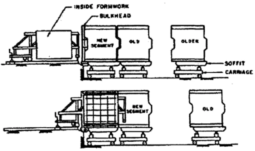
In the short-line method (Figure 2.2), the segments are cast at the same place in sta-tionary forms and against a neighboring segment. After the segment is cast, the neighboring segment is taken away and the new segment takes its place, so that another segment can be cast. The space needed for the short-line method is about three times the length of a seg-ment, small compared to the space needed for the long-line method (PTI and PCI, 1978). Curves and twisting of the structure can be obtained by adjusting the neighboring segment. In the short-line method, the elements can be cast in the vertical position to be later used in the horizontal position.
The short-line method has a disadvantage. To obtain the desired structural configu-ration, the neighboring segment must be positioned with extreme accuracy.
The length of the precast segment will depend largely on what equipment is avail-able for transporting, lifting and prestressing. When choosing what is going to be the size of the segments, it has to be decided between having segments with the same length or having segments with the constant weight (Wium and Buyukozturk, 1984). Designing for the same length has the advantage that less adjustments are needed for the formwork. Meanwhile, designing for constant weight means having the advantage of always transporting and lift-ing units at full capacity which could reduce the construction time.
2.4.2 Erection Methods
There are four methods used to assemble a segmental bridge: the balanced cantilever method, the progressive placing method, the incremental launching method, and the span-by-span method. The method used depends on the length of the bridge or guideway, the individual span lengths, the height of the superstructure along its length, access to the area below where the superstructure is going to be, and the available equipment.
In the balanced cantilever method, a segment is placed on top of a column and securely anchored so that it can resist large overturning moments. This segment can be either cast-in-place or precast. Then, other segments are put on each side of the pier, one at a time alternating from side to side, stressing tendons that go through the segments and over the pier. Segments on both sides of the pier balance each other. When the number of seg-ments on each side of the pier is not equal, there is a large unbalanced moment at the col-umn. The procedure is repeated until the cantilever segments from adjacent piers meet at midspan. The segments used can be either precast or cast-in-place.
The progressive placing method is very similar to the balanced cantilever method. The difference is that the construction starts at a pier and proceeds in only one direction. Therefore, in this method, a cantilever can be almost as long as the length of the span being constructed. The bending moments on the columns are substantial, often requiring the use of temporary intermediate supports.
In the incremental launching method, the construction of the superstructure is per-formed from the top of an abutment. A segment is cast on top of the abutment. The segment is cured and prestressed, and then moved forward, so that a new segment is cast against this segment. Then, prestress is applied to the segments, and both segments are moved forward. This procedure is repeated, and the superstructure spans from pier to pier until it is com-pleted. Very often, a steel launching nose is attached to the deck of the first segment in order to reduce the free cantilever length of the first span. Temporary piers or temporary stays might be used in cases where the negative moments are too large.
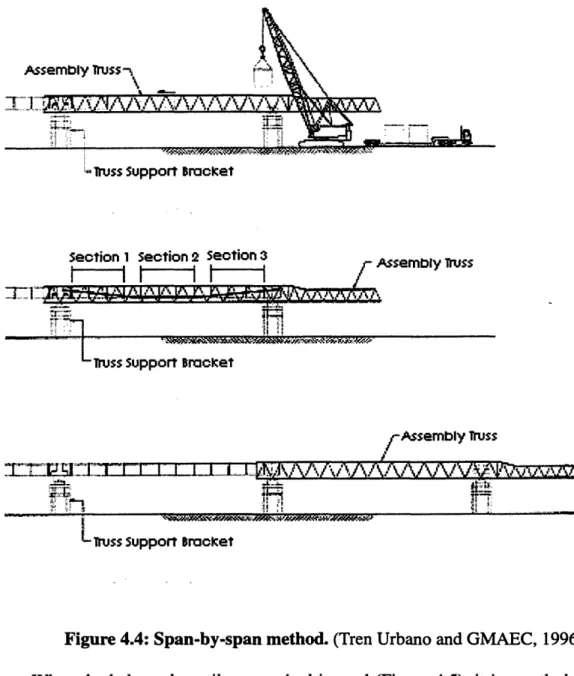
In the span-by-span method, a supporting system is used to place all the segments of a given span during construction. This structure can be a truss fixed at the columns that
sup-ports the segments (in case of precast construction) or formwork (in case of cast-in-place construction) from below, or it can be a truss that holds the segments or formwork from above the deck. Since this method uses the truss, the length of the spans of the bridge to be constructed is limited to the length of the truss.
The method used to erect precast units for any of the previous methods will depend on the site conditions. They can be lifted and put in place by using a crane on the ground or a barge. They can be lifted using equipment on the deck of previously erected units, or, in the case of erection using the span-by-span method, they can be placed using a launching gantry.
The launching gantry can be supported by the completed piers, by the completed parts of the superstructure, or by both. They are very expensive and are only used economi-cally in large projects. They are very useful when the area under the superstructure can not be used for the delivering of precast units or for operating erection equipment.
2.4.3 Joints
When placing the segments to create the superstructure, the segments can be placed together using contact joints or cast-in-place joints. One type of contact joint is the dry joint, which does not need any filling material between the segments, but the most popular is the epoxy joint. In the epoxy joint, the adjacent segments have matching surfaces, and a very thin layer (less than 1 millimeter) of epoxy coating is used between the segments.
Epoxy has many uses. It acts as a lubricant when placing the segments and works as a glue that helps the segments act as a single unit. Also, epoxy helps correct some of the irregularities between the mating surfaces of adjacent segments, and serves as waterproof material for the joints between segments.
Cast-in-place joints are made using mortar and concrete. They are wider than the epoxy joints. Mortar or unreinforced concrete has been used frequently for joints between segments of 24 to 100 millimeters. Reinforced concrete has been used for joints from 200 to 600 millimeters, where the reinforcing steel from adjacent segments is lapped or welded together (Degenkolb, 1977).
Mortar and concrete joints do not require the exact fitting that epoxy joints need, but they are not suited for cantilever construction. This type of joint is mostly suited for con-struction using falsework.
Today, almost all the joints used in segmental construction are contact joints. Cast-in-place joints are mostly used when the alignment needs to be corrected (Wium and Buyukozturk, 1984), and to make a a final adjustment in a span of contact joints.
2.4.4 Railroad Bridges and Guideways
Segmental prestressed construction is as suitable for rail transit and railroads as it is for highways. The procedure for designing an elevated railway is similar to that of a high-way bridge. The difference lies in the larger design life and impact loads for railroad struc-tures. Therefore, elevated railways are more stocky than highway bridges.
In the case of a railway bridge, the actual load applied to the structure is much closer to the design load than in the case of a highway bridge. Therefore, fatigue and durability of railway structures could be a problem and need careful consideration (Podolny and Muller, 1982). This is made even more important due to the fact that the maintenance and repair of railway structures could cause unacceptable disturbance in the train operation.
Usually, ballast is used across the railroad bridge so that the ties and rails are kept in proper alignment and grade separate from the bridge structure. Typically, for rail transit, the
ballast is not used, and either the ties are fixed directly on top of the deck, or the track is set directly on pads and shims attached to the bridge deck, eliminating the use of ties and bal-last. When using ties, they can be made of wood, steel, reinforced concrete, or prestressed concrete. Whichever system is used to fixed the track to the deck, it should have drains or sufficient slope so that water is not trapped.
Until about 30-40 years ago, all tracks, in all networks, were laid by leaving gaps between consecutive rails, and then jointing the rails with fishplates (Profillidis, 1995). The gaps and fishplates were used to permit elongations in the rail due to temperature changes. The use of fishplates has many problems (Profillidis, 1995):
1. It significantly reduces passenger comfort.
2. It causes considerable wheel and rail fatigue and wear.
3. A bumping noise is produced when the vehicle's wheels run on top of it. 4. It greatly increases maintenance expenses.
An alternative to jointed rails is the continuous-welded rail (CWR). A CWR is formed by putting together discrete pieces of rail, eliminating the use of fishplates. No ther-mal expansions along the length of the rail are permitted. This generates forces in the rail that it must be able to resist.
The cost of installing CWR is higher than that of installing a jointed rail. Neverthe-less, the CWR provides an adequate return in capital for the initial investment by reducing maintenance cost, improving track stability, permitting the achievement of higher speed by the vehicles, reducing power consumption, slowing the development in track defects, reduc-ing noise, and improvreduc-ing passenger comfort (Profillidis, 1995).
There is a tendency to use continuous-welded rails wherever possible (Fryba, 1996). However, with the introduction of the continuous-welded rail into railroad bridges and guideways, a new problem came up with regard to the interaction between the superstruc-ture and the rail. New forces and stresses are developed with changes in temperasuperstruc-tures. This problem is presented in more detail in Chapter3.
Chapter 3
Design Considerations for Precast Prestressed Segmental
Concrete Bridges and Guideways
3.1 Introduction
Bridge design for any kind of bridge, including precast prestressed segmental con-crete bridges, should always have the same fundamental objectives. In this chapter, these fundamental objectives of bridge design are presented, and what it means to achieve these objectives is discussed. Later in the same chapter, major issues concerning precast pre-stressed segmental concrete bridges are discussed, and how they affect the accomplishment of the fundamental objectives is analyzed.
3.2 Design Objectives
The fundamental objectives of bridge design are safety, serviceability, economy and elegance. A design can only be successful when all four goals have been achieved. The rel-ative importance of each objective is going to be defined by the consequences of not achiev-ing them (Menn, 1990). Thachiev-ings get further complicated by the fact that all four objectives are interrelated. For example, it is possible that making a structure more aesthetically pleas-ing may mean added costs that would make it less economical.
3.2.1 Safety
A bridge is safe when it is known that it is not going to collapse under the applied loads. The achievement of safety for a bridge structure is mostly believed to be scientific process (Menn, 1990). A bridge designer follows design codes, and a bridge is designed to
resist ultimate loads. When an ultimate load is applied and the structure resists the load, then it is said that the applied and resisting loads are in equilibrium. If an applied load exceeds the value of an ultimate load, the structure is not in equilibrium and, therefore, col-lapses. If all the steps in the design and construction process are followed accordingly, and if the structure is inspected properly and given the necessary maintenance, the bridge is said to be safe, and the structure is not supposed to collapse as long as the values of the ultimate loads are not exceeded.
The fact is that the value of both, the loads to which the structure is subjected and the ultimate load which the structure can resist, are not known exactly. Both are functions of many different factors. Among other things, the loading will depend on the actual traffic patterns that use the bridge, the wind loads and earthquake loads to which the structure is subjected, the settlements taking place in the foundations, and the changes in temperature that occur in the structure. Likewise, the ultimate load the structure resists will depend, among other things, on the actual strength of materials, the workmanship given in the con-struction, the deterioration the structure suffers, and the inspection and maintenance given to the structure. That is why design codes have factors of safety included in their procedure. There are factors of safety that make the expected applied load larger, and factors of safety that make the expected structure resistance lower.
Design codes are not infallible. Bridges that have followed design codes have been known to collapse. Sometimes this is because the applied loads were larger than expected, even with the use of factors of safety. At other times it was because the structure was not constructed according to its design, or because it was not given the proper inspection and maintenance. At times design codes improperly simulate the structural action of bridges.
The factors of safety and equations found in design codes are trying to simulate what will happen to the structure in reality. Sometimes the simulations are not as close to reality as they need to be. Therefore, codes are revised and changed, trying to get closer to reality and helping in the design of safer structures.
In spite of all of the above, safety is not only achieved by following the design codes. The codes do not specify which material to use for construction, what method of construction to use, how to arrange the components of the structures, and many other issues that arise in the design phase. These issues, that have to be decided by the designers, are also going to play a role in determining how safe the structure will be. Therefore designers must use their creativity and common sense, as well as their personal and observed experi-ences with similar projects. It is good to know what has gone both, right and wrong, with similar projects so that this knowledge can be used in the design of a safer structure.
3.2.2 Serviceability
Serviceability is an issue very similar to safety. It is sometimes believed to be achieved completely through scientific procedures by following design codes (Menn, 1990). In reality, this will also depend on the creativity, common sense, knowledge, and experience of the designer.
A bridge is serviceable when it fulfills the need for which it was designed in a posi-tive manner. The most important aspects of serviceability are appearance, function, and durability (Menn, 1990). Appearance refers to giving the impression that the structure is secure. The showing of cracks and large deflections can give the impression that a structure will fail if used, although it may not. Function refers to how the bridge works when used. The bridge should be safe for the users (and for any traffic that passes under it) during both
normal and emergency conditions. It should not be uncomfortable, and it must meet the requirements of abutters and the aspirations of the community as a whole. Finally, durabil-ity refers to remaining in service or remaining fit for use for a long period of time.
There are aspects of serviceability that can be quantified such as deflection, vibra-tion, cracking, run-off of rain water on the deck, and traffic volumes. These aspects can be fulfilled by following design codes and following proper construction procedures. Other aspects, that can not be quantified, need of the creativity and experience of the designer to be provided, for example, corrosion of the bearing system. The designer should think of protecting the system against corrosion, and provide for easy inspection and replacement of components in case of corrosion.
A bridge will deteriorate with time. The more serviceable will deteriorate slower. In any case, all bridges need inspection. Therefore, inspection is very important in maintaining a bridge serviceable, like proper design and construction are too.
3.2.3 Economy
Economy in bridges is about getting as much as possible out of money. It is not about spending the least possible amount of money in the construction of the bridge. The big picture has to be seen, and costs incurred in operation, maintenance, rehabilitation, and
demolition of the bridge have to be considered too.
When a bridge is designed, a number of decisions have to be made. These decisions will impact the cost of construction, and other costs in the long run. They include the selec-tion of materials, the type of construcselec-tion to be used, how will the workers get organized, details of the structure, and the equipment to be used. Also, an appropriate strategy has to be established for construction, maintenance, rehabilitation, and ultimate disposal.
As mentioned earlier, every bridge deteriorates. The difference is how fast they dete-riorate. This will depend on those very first decisions made for the construction phase. How it deteriorates will impact the operation of the bridge and the maintenance needed for the bridge to remain serviceable. Also, how the bridge deteriorates will determine if the bridge needs at some point in the future a major rehabilitation, or how can it be disposed of the structure in the case is deemed the bridge is not useful anymore. Operation, maintenance, rehabilitation and demolition represent costs, and they can be very substantial.
The important thing to remember here is that when aiming for cost-effectiveness in the design of a bridge, the future operation, maintenance, rehabilitation and demolition, as well as the present (or immediate future) construction costs must all be thought of. The best tool the designer has to determine the cost effectiveness of a bridge is the life-cycle cost, in which the total cost of the bridge is calculated for the life-span that the bridge is designed for.
3.2.4 Aesthetics
The issue of achieving aesthetics in bridges can, at first, appear to be very compli-cated, because beauty is believed to be very subjective. In reality, by checking the literature written by experts in aesthetics of bridges, it can be found that there is agreement on most of the major issues of elegance in bridges.
The experts agree that bridges must be adequate for their surroundings, whatever they are. As Ritner (1990) explained: "visual beauty is something that is not awkward, it is something that does not appear to be out of place". At the same time, the bridge structure can be perceived as an individual entity (Menn, 1990, 1991), therefore its beauty will also depend on the bridge's structural form.
Commonly believed ways of achieving an elegant bridge include: using efficiently the materials for a structure that is slender and transparent as opposed to heavy and massive; integrating harmonically all the structures components into one coherent, organized struc-ture; making the structure symmetrical; designing for simplicity without unnecessary orna-mentation; and, incorporating topographical features of the surroundings.
As for safety, serviceability, and economy, when designing for aesthetics, the future must be kept in mind. How the bridge will deteriorate has to be considered, along with what kind of maintenance must be given to keep its elegance has to be thought through.
In many cases, the first obstacle that has to be crossed in order to get an aesthetically pleasing bridge is to have the bridge designer understand that making a bridge more elegant does not always means having a more expensive structure. Sometimes money has been saved by changing a bridge design to make it more elegant. And in the cases where making a design more elegant means an increase in cost, the changes should not always be dis-carded just for the sake of saving money. The designers have to understand that the public does care about having an aesthetically pleasing bridge, approaching the decision of adding cost for elegance as they would do for adding a safety feature that would increase the cost of the bridge (Gottemoeller, 1990, 1991).
The majority of bridges are designed by engineers who have no formal education in aesthetics. That is why the engineer must work together with a person who does have the formal education: the architect (Lacroix, 1990). It is in public agencies on whom the responsibility of designing, building, maintaining, and as consequence, achieving elegance in bridges falls (Kruckemeyer, 1990). Therefore, they should get architects to be involved in the design of public bridges.
3.3 Major Issues in the Design of Precast Prestressed Segmental Concrete
Bridges and Guideways
In 1994, the American Segmental Bridge Institute (ASBI) published in the PCI Jour-nal the results of a survey in which the performance of 96 segmental concrete bridges of the United States and Canada was evaluated (Miller 1994). The major conclusions of this report were:
1. Segmental concrete construction performs well over time, with consistently high condi-tions ratings for bridges that have been in use for up to 30 years.
2. The performance of post-tensioned segmental concrete is similar to that of other pre-stressed concrete bridges.
Though it has been found that precast prestressed segmental construction is a very good method of construction, it is still not perfect. In this section are presented important design decisions and possible sources of problems related to precast prestressed segmental concrete bridge. Some of the decisions and problems are not exclusive to precast pre-stressed segmental construction. It will be shown how these decisions and problems will affect the achievement of the four before mentioned objectives of bridge design.
3.3.1 Continuity
One decision to be made in a bridge or elevated guideway design is what kind of span configuration should be used. Basically, a decision must be taken between using sim-ple spans or a continuous system. Furthermore, if a continuous system is selected, then a continuous unit needs to be chosen (two span continuous, three span continuous, etc.). Selecting a continuous system over the use of simple spans will have an effect on a number of important aspects of the structure. Some of these effects are positive, and some are not.
In a simple span configuration, the maximum moment on each beam occurs at mid-span, while the moments at both ends are zero. If the configuration is changed to continu-ous, the moment at midspan is reduced, while the maximum moments occur on the section of the unit that passes on top the support continuously. The moments at the end of the con-tinuous unit are zero.
A problem with using a continuous design is that it is much more difficult than mak-ing the design of a bridge in which all its spans are simply supported. It is important that the bridge designer realizes that there are many possible advantages that can be taken out of designing a more continuous structure and that it is worth going through the trouble. Not exploring the possibility of using a continuous system could mean not achieving the four objectives of bridge design.
Safety
If a bridge design is changed from using simple spans to using continuous units while the size of the cross-section is not changed for the new design, the stiffness of the girders would be increased. Therefore, the continuous unit could resist heavier loads than the simply supported member.
Another advantage obtained by using continuity is that the over-all structural stabil-ity is improved through redundancy. Continustabil-ity increases safety margins by allowing the redistribution of stresses under overload conditions (Taly, 1998). Also improved is the response to dynamic loads such as earthquake and wind loads. This happens because increasing the continuity of the structure means having more columns connected to the girder, which is what causes the improvement of stability, and provides a better mechanism to resist horizontal loads.
Another way of improving resistance of lateral loads, is that by increasing continuity of a design, the maximum moments at mid-span are reduced, therefore allowing for a reduc-tion in the size of the girder cross-secreduc-tion. This reduces the weight of the structure which, in turn, reduces the momentum of the structure, which reduces the lateral loads to be resisted (Taly, 1998).
Is not always better to increase continuity. As explained before, in the columns where the superstructure pass over continuously, there is a concurrence of moment and shear at the support sections, which reduces the moment strength at this locations. Also at these columns, new lateral forces and moments are formed. These forces are caused by the elastic shortening of the long-span beam under prestress, and by horizontal loading that could come from earthquakes, acceleration and breaking of vehicles, and temperature changes. Additionally, the secondary stresses, usually produced by shrinkage, creep, tem-perature variations, and settlement of the supports, are magnified when compared to a sim-ply supported structure. All these possibilities need to be considered, and the supports may need more reinforcement, be made more flexible or made larger.
Another possible problem that could present itself if the continuity of a bridge design is increased is the reversal of moments. If live loads are much heavier than dead loads, and if partial loadings on the spans are considered, the beam can be subjected to seri-ous reversal of moments. This problem could be addressed for by using partial prestressing (in which some tension is allowed in the concrete).
Serviceability
By changing a bridge design from using simple spans to using continuous units, if the size of the cross-section that would be used for the simple span design is kept, the
stiff-ness of the girder would be increased. Therefore, the continuous units would have a smaller deflection than the simply supported.
The number of expansion joints and bearings used could be reduced by increasing the continuity of the bridge. This means that the structure would require less of the inspec-tion and maintenance associated with expansion joints and bearings. Other problems associ-ated with expansion joints, such as leakage, and corrosion of the reinforcement and the bearing support system, could be minimized. Also, by reducing the number of expansion joints, the number of bumps felt by riding over them is reduced, thus the ride comfort is
improved.
The problem with an increase in continuity is that there are going to be greater elon-gations at the free-ends caused by an increase in temperature. Therefore, bigger and more complex expansion joints have to be provided. It is more difficult to provide sealant for these joints.
Economy
If a bridge design is changed from simple span to continuous, the size of the cross-section can be reduced due to the reduction of the maximum moments and stresses at the midspan. Having a smaller cross-section means a reduction in the cost of materials and, possibly, construction. Also, the structure would be lighter, which means that the columns and foundations can be lighter, which, in turn, means further reduction in the cost of materi-als and, possibly, construction. Alternatively, the span length could be increased with conti-nuity which, in turn, could mean that the number of piers to be constructed could be reduced.
By increasing continuity, the number of anchorages needed to tension the steel at intermediate supports can be reduced when compared to the quantity used for simply sup-ported members. This means further reduction in costs and labor.
The number of expansion joints and bearings is reduced by increasing the continuity of a bridge. This means that the structure would require less inspection and maintenance, and therefore, there would be a reduction in cost. Sometimes, depending on the develop-ment of new lateral stresses, the width and thickness of the piers can be reduced by reducing the number of bearings, which means further savings of materials. Other problems associ-ated with expansion joints, such as leakage and corrosion, could be minimized, therefore the possibility of having to perform what could be a very costly bridge rehabilitation are reduced.
In continuous beams, various spans can be prestressed with the same continuous tendon by providing and undulating profile, resulting in the reduction of anchorages needed. This is not always possible, because there could be a non-acceptable reduction in the pre-stressing force when continuous tendons are used due to the friction between the prestress-ing steel and the duct through which the steel pass caused by the increase number of bends that the tendon has to go through.
Various disadvantages that come with continuity are: the concurrence of moment and shear at the support where the superstructure passes over continuously; excessive lateral forces and moments at this supports due to the elastic shortening of the long-span beam under prestress and by horizontal loading that could come from earthquakes, acceleration and breaking of vehicles, and temperature changes; and, the secondary stresses, usually pro-duced by shrinkage, creep, temperature variations, and settlement of the supports, are
mag-nified when compared to a simply supported structure. Therefore, these supports require more reinforcement, unless the reduction of the moment strength at this section is accept-able.
Aesthetics
As mentioned before, continuity allows the reduction of the cross-section of the beam. This permits having a slender, hence more elegant, structure than a bridge that uses simple spans.
Again, by increasing the continuity of a bridge, the number of expansion joints and bearings needed could be reduced. This causes the reduction of the possible leakages of the expansion joints that causes the staining of the substructure (Wasserman, 1991). Also, by reducing the number of bearings, the width and thickness of the piers can be reduced, which makes the structure more aesthetically pleasing (Menn, 1990).
3.3.2 Expansion Joints
Another important decision that has to be made when designing a bridge or a guide-way is the selection of expansion joints to be used. The ones chosen must be fit to handle displacements of the structures such as those caused by the changes in temperature or seis-mic loads. According to David J. Lee(1994): "expansion joints should, more correctly, be known as movement joints since they cater for relative movement between bridge deck spans and abutments resulting from a number of causes not exclusively due to the tempera-ture".
There are two ways in which expansion joints can be classified. The first way is by classifying them as either open gap or covered gap (K6ster, 1969). The use of this classifica-tion has to do with the riding quality of the expansion joint when the joint is used in
high-ways, as opposed to when it is used in rail transit, where the vehicle does not make contact with it. The classification has nothing to do with the sealing used. The other method of clas-sification is based on the size of the movement the joint has to take into account. They can be classified as joints for small movements, for medium movements, or for large move-ments (Lee, 1992).
All over the world, bridges deteriorated due to faulty expansion joints. Usually these joints have defective or ineffective waterproofing, or poor drainage details.
Serviceability
Expansion joints are located in an extremely vulnerable position. They are subjected to the impact and vibration of traffic, and exposed to both the effects of the natural elements (water, dust, grit, ultra-violet rays, and ozone) and applied chemicals (salt solutions, cement alkalis, and petroleum derivatives).
The expansion joints must fulfill the following conditions (Lee, 1994): 1. accommodate horizontal and vertical movements of the structure;
2. withstand applied loadings;
3. be hardly noticeable when ridden on top of it, therefore not being a hazard to any kind of road user;
4. resist corrosion and withstand attack from grit and chemicals;
5. require little maintenance;
6. permit easy inspection, maintenance, repair or replacement.
7. prevent the penetration of water, silt, and girt, or provide for their removal.
The lifetime of the expansion joint will depend on the chosen model, the type of structure which it serves, the quality of the workmanship given at installation, and the traffic it is subjected to (Chabert and Ambrosino, 1996). Problems have been registered with
expansion joints for the seven conditions mentioned above. When expansion joints are not performing well (either because of improper design or improper installation), they can be a
nightmare for the serviceability of a bridge.
If an expansion fails while the joint is used in a highway bridge, it becomes quite noticeable to the riders in vehicles. Also, if the waterproofing fails, damage can be caused to the reinforcing steel of the beams end that the joint is supposed to protect, accelerating the deterioration of the bridge. The elastomeric bearings can also get affected with the corro-sion of its reinforcing steel. The same can happen to the piers. The fact that the expancorro-sion joint fails means that it is going to need replacement, creating additional maintenance for the bridge. Also, the deterioration of the joint causes new forces and stresses in the bridge that were not accounted for in the design.
Therefore, it is important to give special attention to expansion joints. When care-fully designed and detailed, properly installed, and given reasonable maintenance, expan-sion joints should be trouble-free for many years.
Economy
There is a large selection of expansion joints in the market. It is important to choose one that gives good performance and trouble-free life for at least as long as that of the sur-facing. They should be properly installed, and given the necessary inspection and mainte-nance. Otherwise, the expansion joint could start producing problems that could be costly to fix. If they don't work properly: they could permit leakage that could cause the corrosion of reinforcement and of the bearing system; and they would have to be replaced with new expansion joints.