Publisher’s version / Version de l'éditeur:
Vous avez des questions? Nous pouvons vous aider. Pour communiquer directement avec un auteur, consultez la première page de la revue dans laquelle son article a été publié afin de trouver ses coordonnées. Si vous n’arrivez pas à les repérer, communiquez avec nous à PublicationsArchive-ArchivesPublications@nrc-cnrc.gc.ca. Questions? Contact the NRC Publications Archive team at
PublicationsArchive-ArchivesPublications@nrc-cnrc.gc.ca. If you wish to email the authors directly, please see the first page of the publication for their contact information.
https://publications-cnrc.canada.ca/fra/droits
L’accès à ce site Web et l’utilisation de son contenu sont assujettis aux conditions présentées dans le site LISEZ CES CONDITIONS ATTENTIVEMENT AVANT D’UTILISER CE SITE WEB.
The 22nd Canadian Hydrotechnical Conference, Water for Sustainable
Development: Coping with Climate and Environmental Changes [Proceedings],
2015-04
READ THESE TERMS AND CONDITIONS CAREFULLY BEFORE USING THIS WEBSITE.
https://nrc-publications.canada.ca/eng/copyright
NRC Publications Archive Record / Notice des Archives des publications du CNRC : https://nrc-publications.canada.ca/eng/view/object/?id=4647ffd8-0f2a-4500-8989-7d258d6cc997 https://publications-cnrc.canada.ca/fra/voir/objet/?id=4647ffd8-0f2a-4500-8989-7d258d6cc997
NRC Publications Archive
Archives des publications du CNRC
This publication could be one of several versions: author’s original, accepted manuscript or the publisher’s version. / La version de cette publication peut être l’une des suivantes : la version prépublication de l’auteur, la version acceptée du manuscrit ou la version de l’éditeur.
Access and use of this website and the material on it are subject to the Terms and Conditions set forth at
Physical modelling and design optimizations for presidente kennedy
terminal, Brazil
PHYSICAL
MODELLING
AND
DESIGN
OPTIMIZATIONS
FOR
PRESIDENTE KENNEDY TERMINAL, BRAZIL
S. Baker1, K. Mahlujy2, P. Knox1, and A. Cornett1 1. National Research Council, Ottawa, Ontario, Canada 2. Ausenco, Vancouver, British Columbia, Canada
ABSTRACT: This paper discusses two 3D physical hydraulic model studies conducted in support of the
design for a new iron ore exporting terminal located offshore of Espírito Santo, Brazil. The proposed terminal consists of a 5km long trestle, an iron ore export berth, an offshore berm breakwater, and a dredged access channel. The first model study was conducted to study wave agitation and moored vessel motion in order to estimate berth availability (downtime) for the new port, optimize and verify the breakwater length, and evaluate a softer mooring system. A 1:70 scale model of the surrounding bathymetry and preliminary terminal layout was constructed, and then modified to simulate several alternative layouts. The second model study was conducted to verify and optimize the breakwater design, which was devised as a dynamically stable berm breakwater featuring two roundheads, three straight trunk sections, and two bends. The breakwater stability study was performed in two stages (quasi-3D and fully-3D) at a scale of 1:40. The stability of the berm breakwater and the changes in breakwater profile shape under various storm intensities were analyzed in detail, and many optimizations to improve the breakwater performance, constructability, and cost effectiveness were investigated and assessed.
Keywords: physical modelling; wave agitation; moored ship motion; berm breakwater stability, coastal
engineering.
1. INTRODUCTION
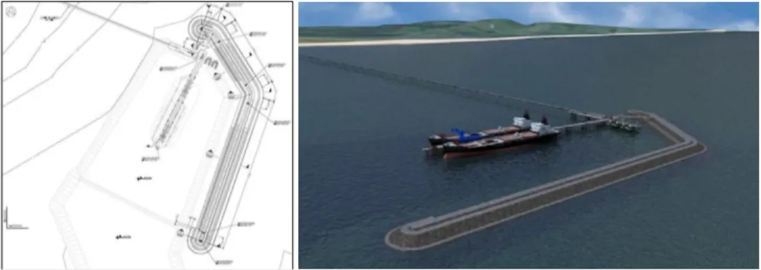
“Porto Presidente Kennedy” will be located in the south eastern portion of Espírito Santo state, approximately 300km northeast of Rio de Janeiro, Brazil. The port is to be constructed as part of a new large-scale iron ore development in Brazil. The new port will feature two offshore berths sheltered behind a ~1,200m long rubble-mound breakwater located near the -15m depth contour. Typical ore carrier vessels intended for the port range in size from approximately 60,000 DWT to 220,000 DWT. These large vessels will access the new berths by transiting an approach channel dredged to a depth of 23m.
The breakwater layout was determined using both a numerical Boussinesq wave diffraction model and a numerical ship motion model. In parallel, a trade-off study evaluated four breakwater concepts, from which a dynamically stable berm breakwater was selected for the base design (see Mahlujy & Prasad, 2013). The breakwater features two roundheads, three trunk sections, and two bends. Figure 1 shows concept images for the future port.
22nd Canadian Hydrotechnical Conference 22e Conférence canadienne d’hydrotechnique
Water for Sustainable Development : Coping with Climate and Environmental Changes L’eau pour le développement durable: adaptation aux changements du climat et de l’environnement
Figure 1. Concept sketches of Port Kennedy (source: Ferrous).
2. PHYSICAL MODELLING STUDY OF WAVE AGITATION AND MOORED SHIP MOTION 2.1. Study Objectives and Approach
A program of physical hydraulic model studies was conducted to investigate the wave agitation, mooring line and fender forces, and vessel motions for a bulk carrier ship moored at the new berths considering a wide range of incident wave conditions. The moored ship motions and mooring forces were ascertained and compared with safe working limits based on design guidelines published by PIANC (1995, 2012) to estimate berth availability (the portion of a typical year that safe and efficient cargo handling will not be affected by adverse wave conditions) for various alternative breakwater lengths, mooring configurations, and ship ballast conditions.
The studies were conducted in a 47m long by 30m wide by up to 0.8m deep wave basin located in NRC’s laboratory in Ottawa, Canada. A 1:70 scale 3-D physical model of the planned port (including the berths, breakwater, and surrounding bathymetry) was constructed for this study, and then modified to simulate several alternatives. Froude scaling laws were applied to estimate prototype behaviour from observations and measurements in the model. Many of the methods and modelling technologies described in Cornett (2014) were employed in this study. The model was fitted with two portable computer-controlled wave machines to generate waves, nineteen wave gauges to measure wave conditions, spending beaches to absorb the waves around the perimeter of the model, five fender simulators, six mooring line simulators, eleven load cells to measure mooring line and fender loads, and an optical motion tracking system to measure the 6-axis motions of the moored ship.
All tests were conducted with a model ship moored at the berth (except during the wave calibration phase before the breakwater and berth were constructed). An existing model ship from NRC’s inventory was selected and prepared for use in the study to represent a 70,000 DWT Panamax bulk carrier. This vessel is generally representative of smaller ships expected to use the berth over the coming decades. This vessel size was selected presuming that operating thresholds for a larger Capesize vessel would be higher, therefore modelling a Panamax vessel would be conservative. Numerical ship motion modelling using AQWA confirmed this assumption (see Mahlujy & Prasad, 2013). Ballasting weights were distributed within the model Panamax ship in order to replicate several desired vessel characteristics at model scale. The total amount of weight added was governed by the required displacement (or mass), while the spatial distribution of the weight was optimized to match target values for the metacentric height, GM, and the vessel radii of gyration about the x- and y-axes, kxx and kyy. Ballasting weights were added to replicate two
loading conditions, 40% loaded and fully loaded.
2.2. Physical Model Description
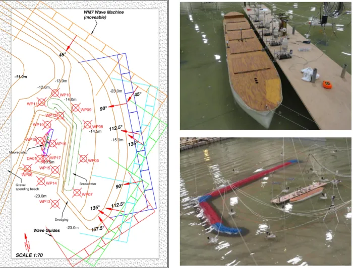
The 1:70 scale physical model (see Figure 2) represented a 6.9km2 rectangular area (3.29km by 2.10km) of prototype terrain. The model included faithful scaled reproductions of the proposed breakwater, the two ship berths, the surrounding bathymetry, and the dredged areas affecting wave conditions at the site. Wave absorbing spending beaches, comprised of permeable gravel placed at a mild 1:10 slope, were
constructed in the model in order to minimize spurious wave reflections from the model boundaries. This type of spending beach features excellent wave absorption characteristics over a wide range of frequencies. Several portable wave absorbers were also used to dampen wave agitation behind the wave machines.
Figure 2. Layout of the 1:70 scale 3-D physical model of Port Kennedy.
Vertical fluctuations of the free surface (waves) were measured in the model using nineteen capacitance-wire wave gauges, which operate by sensing the change in capacitance that occurs as a portion of the insulated wire becomes wetted. Four of the gauges were arranged in a compact array in order to collect the information necessary to resolve the directional properties of the wave field.
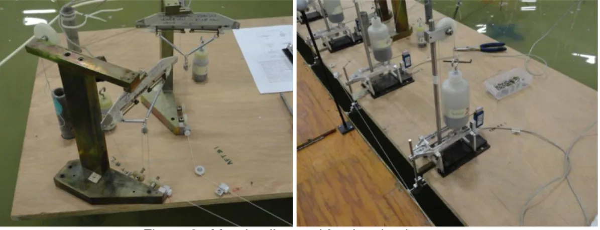
Six mooring line simulators were used to model the mooring lines in this study. These specialized devices make it possible to reproduce the non-linear elastic properties of a mooring line while recording the tension using a shear-beam type load cell. In addition, mooring line pretension can be set using a simple counterweight (see Figure 3). In this study, different spring assemblies were prepared in advance to simulate the non-linear load-elongation properties of each mooring line. The load-elongation characteristics of the model mooring lines were tested on a calibration bench and adjusted to match a pre-defined target curve, derived to replicate the prototype mooring arrangement.
Mechanical devices known as fender simulators were used in the model to represent the action of the fenders and measure the compressive loads exerted on the fenders by the moored ship (see Figure 3). Two different types of prototype marine fender were simulated in this study. The Super Cone-type fenders are designed to buckle (yield) under extreme loads, while for the Air Block-type fenders, the reaction continually increases with increasing compression. The Super Cone-type fenders were represented in the
-20.5m -23.0m -15.0m SCALE 1:70 -14.5m -23.0m -14.0m Breakwater Dredging Gravel spending beach Wave Guides WM7 Wave Machine (moveable) Moored ship -23.0m 45° 90° 45° 112.5° 135° 90° 157.5° 135° 112.5°
model using two-stage simulators that were able to simulate buckling. In order to simulate the Air Block-type fenders, the two-stage simulators were modified to prevent buckling. Each fender simulator was configured to simulate the behaviour of a single prototype fender and the spacing between the simulators was selected to replicate the prototype situation.
Figure 3. Mooring line and fender simulators.
An optical motion tracking system was employed to measure the motions of the moored ship in this study. The system consists of a pair of special cameras, an array of reflective targets mounted on the ship, a video processor, and specialized software. The cameras emit synchronized bursts of infrared light that travel towards the model vessel and are reflected by the array of passive reflective markers rigidly mounted to the vessel. The cameras capture the reflected light, which is then analyzed by a video processor, which calculates the position of each marker in three dimensions. Specialized software is then used to calculate the exact position and orientation of the marker array, and thus the vessel, in three-dimensional space, all in real-time. Further analysis of the 3D motion data was undertaken to compute the movements of key locations on the ship, such as the centre of gravity and the loading hatches.
Operational wave conditions at the site include a combination of sea and swell waves approaching primarily from NNE to SE sectors (see Figure 4). Significant wave heights (Hs) of 2.0m and 2.5m are
exceeded 6% and 1% of the time, respectively. Peak wave periods (Tp) range from 4 to 14s, with 10% of
peak periods exceeding 14s. The design wave condition based on a 100-year return period (peak storm event) is Hs = 3.9m and Tp = 8s.
Figure 4. Operational wave climate roses.
In this study, various irregular long-crested wave conditions were generated which approached the port from five different directions: 45°, 90°, 112.5°, 135°, and 157.5°. The waves were generated by means of a pair of portable computer-controlled wave machines. Portable guide walls were used to guide the waves from the wave machines towards the port. Since this study focused on operational wave conditions, the incident wave conditions featured significant wave heights from 0.5 – 2.5m with peak periods from 6 – 20 seconds.
2.3. Results
2.3.1 Effect of Breakwater Length
Three different breakwater lengths were examined in this study: the full ~1,200m length specified in the preliminary design; with 100m removed from the southern end; and,
with 200m removed from the southern end.
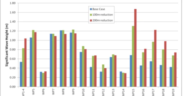
Figure 5 shows a comparison of significant wave height observed at each wave gauge during a test with seastate “F3f” (irregular waves with Hs = 1.00m, Tp = 16.0s, approaching from 135°). The wave gauge layout can be seen in Figure 2. As expected, the changes in breakwater length have only a very small influence on wave conditions at locations east of the breakwater (specifically WP05, 07, 08, 09 & 10), and at locations not sheltered behind the breakwater (WP06, 13, & 14). However, for locations near the berths (WP1-4, WP16, 17, 18, & 19), notable increases in significant wave height were observed as the breakwater was shortened, as expected. Corresponding increases in mooring loads and moored ship motions were also observed. The physical model was used to quantify the increases in wave disturbance, peak mooring line tensions, peak fender loads, and moored ship motions associated with reducing the breakwater length by 100m and 200m. These results were subsequently used to estimate berth availability (downtime) for the various breakwater layouts, and to guide the breakwater length specified in final design.
Figure 5. Influence of breakwater length on significant wave heights. 2.3.2 Berth Location
At the outset of the physical modelling study, it was assumed that mooring conditions would be slightly worse at the inshore (western) berth due to the fact that waves diffracting around the ends of the breakwater and interacting with the moored ship would tend to excite yaw and sway motion by pushing the bow and/or stern away from the berth, generating higher loads in the bow and stern mooring lines. Measurements obtained in the model at both berths suggest that in most cases the moored ship motions and mooring loads will be slightly larger at the inshore berth, as expected. The model results suggest that the peak motions and loads at the offshore berth will in general be smaller than or equal to the peak loads and motions at the inshore berth.
2.3.3 Prediction of Downtime
A berth is normally assumed to be unavailable whenever the peak vessel motions in any direction, or the maximum tensions in any mooring line, or the maximum loads in any fender exceed the appropriate safe working limit. The total downtime (or berth availability) is estimated by summing the occurrence frequency for all seastates in which any of the safe working limits are exceeded. Less certain are the most appropriate safe working limits, and the methods that should be used to define the peak motions and maximum loads.
In this study, results from the analysis of vessel motions and mooring forces were used to estimate downtime. A statistical approach was applied wherein the peak load in each mooring line and fender was estimated as a multiple of the root-mean-square (RMS) force. This approach has the advantage that the RMS value is a more statistically stable value than the maximum value obtained from a single test with irregular waves. By conducting several tests, each with different random realisations of the same seastate, an appropriate multiplier was determined for estimating the peak load from the RMS value.
As part of the effort to support the estimation of berth availability or downtime, a number of tests were conducted in which the model port was exposed to ten different pseudo-random realizations of seastate F3 (Hs = 1.00m, Tp = 16.0s, approaching from 135°) synthesized from the same parent wave spectrum.
Each realization had virtually identical significant wave height and peak period, yet featured a unique wave train comprising a different sequence of individual waves. The ratio of Hmax/Hm0 varied from approximately
1.69 to 1.96. RMS fender forces, line loads, and vessel motions were shown to be quite repeatable, similar to the significant wave heights. The peak loads/motions were somewhat more variable, as expected. 2.3.4 Effect of Mooring Line Type
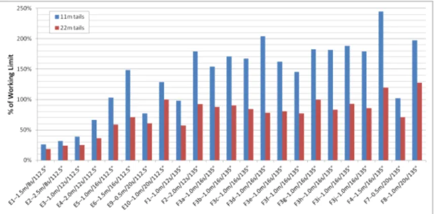
For the Panamax vessel, mooring lines consisting of steel wire rope with 11m long nylon tails were specified and simulated initially. A secondary softer alternative featuring steel wire rope with 22m long nylon tails was also modelled. In the model, the ship was moored using six mooring lines, named ML1 to ML6 moving from bow to stern. While other parameters such as breakwater length, vessel ballast condition, and fender type were held constant, an investigation was undertaken to determine the influence of mooring line type or stiffness. These tests showed that decreasing the mooring line stiffness led to significant reductions in peak mooring line loads (see Figure 6), while the ship motions remained very similar.
Figure 6. Influence of mooring line type on mooring forces. 2.3.5 Effect of Fender Type
While other parameters such as breakwater length, vessel ballast condition, and mooring line type were held constant, an investigation was undertaken to determine the influence of fender type (Super-Cone versus Air Block). Results from the physical model indicate that the type of fender will have a strong influence on peak fender loads, and a mild influence on peak vessel motions. Mooring loads were consistently smaller when Air Block fenders were simulated. Vessel motions were also slightly smaller for the Air Block fenders.
3. PHYSICAL MODELLING STUDY OF BERM BREAKWATER STABILITY 3.1. Study Objectives and Approach
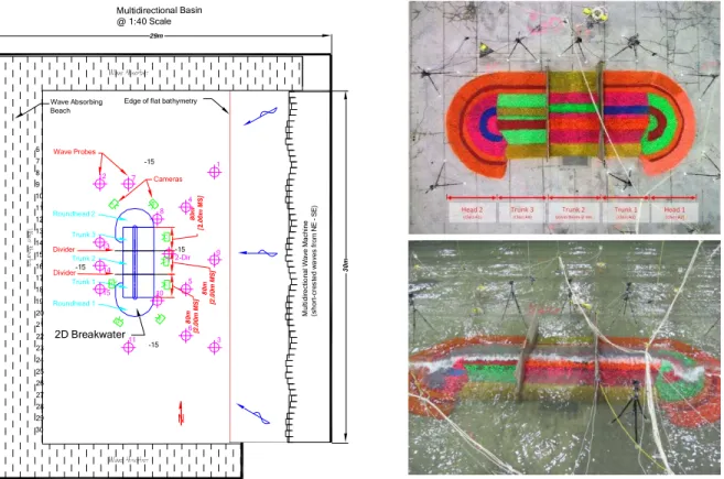
The physical model studies of breakwater stability were conducted in NRC’s 36m by 30m wave basin, equipped with a powerful and sophisticated directional wave machine. The general arrangement of the
1:40 scale quasi-3D physical model is presented in Figure 7. The quasi-3D model consisted of three trunk sections, each 80m long (2m model scale), and two roundheads. The breakwater model was oriented parallel to the wave machine so that long-crested waves generated perpendicular to the wave machine approached the trunk sections head-on. The trunk sections were separated by steel dividers, eliminating the need for transition sections between the various trunk sections. Froude scaling laws were used to design the physical model and estimate prototype behaviour from behaviours observed in the model. The main objective of the quasi-3D modelling was to assess and compare several design alternatives for both the trunk and roundhead, and select preferred alternatives to be used in constructing the fully-3D model which followed.
Figure 7. General arrangement of the quasi-3D physical model at 1:40 scale.
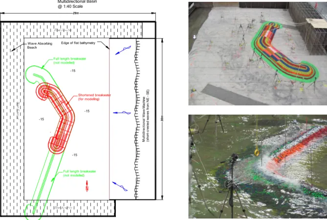
The same 36m by 30m wave basin facility and 1:40 model scale was also used for the fully-3D modelling. Figure 8 shows the entire 1,200m long breakwater at Port Kennedy overlain on the shortened breakwater that was constructed for the fully-3D modelling. The lengths of the north and south trunk sections were shortened to fit the north and south roundheads in the basin at a reasonable scale, yet provide sufficient length to allow two different cross sections to be tested on each trunk. The main trunks that run from the central elbow were both 200m (5m model scale) in length. The model was oriented so that waves generated perpendicular to the directional wave machine approached the model breakwater from due east (90°). Thus, short crested waves with mean directions ranging from 60° to 120° could be generated with good coverage of the model breakwater. The objectives of the fully-3D modelling were to investigate the interaction of extreme (design) seastates with all parts of the breakwater structure, study the structure response, assess the structure performance (including the stability of the rear slope and crest, and the reshaping of the underwater berm), as well as develop and test design alternatives to optimize the design.
1 2-Dir 3 4 5 6 8 12 11 10 13 14 15 2D Breakwater 6 7 8 9 10 11 12 13 14 15 16 17 18 19 20 21 22 23 24 25 26 27 28 29 30 Roundhead 2 Trunk 1 Roundhead 1 Trunk 2 Trunk 3 8 0 m [ 2 .0 0 m M S ] 8 0 m [ 2 .0 0 m M S ] A B C D E F G H Wave Probes Cameras Divider M u lti d ir e cti o n al W a ve M a ch in e (sh o rt-cr e s te d w a ve s fr o m N E S E ) Wave Absorbing Beach Multidirectional Basin @ 1:40 Scale 3 0 m 29m
Edge of flat bathymetry
-15
-15
-15 -15
Figure 8. General arrangement of the fully-3D physical model at 1:40 scale.
3.2. Physical Model Description
The quasi-3D and fully-3D breakwaters were constructed in the wave basin as shown in Figure 7 and Figure 8, respectively. In each case, the breakwaters were divided in sections to investigate the performance of various cross section designs. Careful attention was given to the location, dimensions, composition, and methods of construction of the structures to ensure that the model structures replicated the proposed designs accurately and faithfully. Fiberboard templates were used to guide the placement of the underlayers and armour stone. Elevations were controlled by carefully surveying the templates using an optical level, and were checked after construction for quality assurance. The templates were removed prior to testing. The underlayers and different rock armour gradations were painted different colours to assist in visualizing stone motion and damage. The breakwaters were completely removed and reconstructed prior to each test series.
Wave conditions in the model were measured using 15 capacitance-wire wave gauges. Eight digital cameras that could be remotely operated were deployed in the model to document the state of the model breakwater after each test segment. The movement of individual armour stones can be identified by comparing digital photographs with identical field of view, taken at different times throughout the test program.
Profiles of each of the breakwater sections were taken prior to, during, and at the completion of the fully-3D model testing. The profiling technique used a range pole that was located in the center of the model section with a collar nut secured to the pole and surveyed to a known elevation. A beam was lowered onto the pole to rest on the nut and this beam was levelled. Holes were drilled in the beam at specific locations (for example, at the slope breaks of the neat lines of the cross-section) and slender rods were lowered through the holes until coming in contact with the rocks on the structure. The length of the rods was measured, and the distances were subtracted from the elevation of the beam to give an elevation of the structure. These elevations and offsets were used to develop the profiles of the breakwater section.
Shortened breakwater (for modelling) M u lt id ir e c ti o n a l W a ve M a ch in e (sho rt -cr e s te d w a ves fr o m N E SE ) Wave Absorbing Beach Multidirectional Basin @ 1:40 Scale 30m 29m
Edge of flat bathymetry
Full length breakwater (not modelled)
-15
-15
-15 -15
Full length breakwater (not modelled)
In each test series, the model structure was exposed to a sequence of incident wave conditions and water levels, including short-crested and long-crested seastates with different heights, periods, and mean directions, while the performance of the model structure was observed and documented at regular intervals. These stability tests focused on the storm and extreme wave conditions expected at the site, and featured significant wave heights ranging from 1.3 – 4.7m with peak periods from 6 – 12s, approaching from 60 – 135°.
3.3. Results
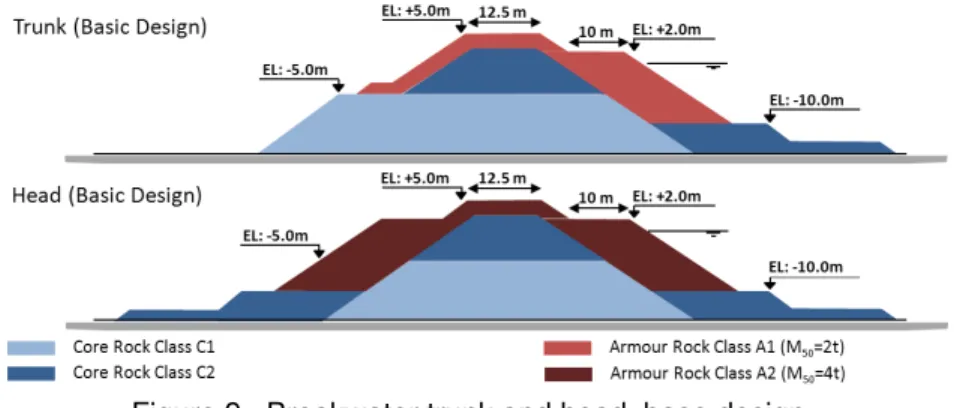
Figure 9 shows the base design tested in the quasi-3D model. Several design alternatives were investigated in this phase, including roundheads constructed with 2 tonne and 4 tonne armour rock, and trunk sections constructed with 1 tonne and 2 tonne stone, as well as berm heights of +2.0m and +0.0m/CD. The results of this initial testing showed that the base case design performed well; however, attempts to reduce the armour rock size and berm elevation of the trunk section were unsuccessful, as were attempts to reduce armour size at the roundhead.
Figure 9. Breakwater trunk and head, base design.
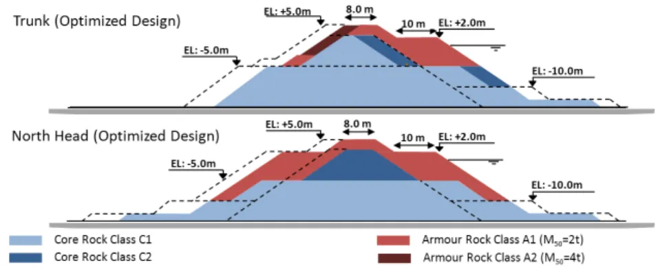
Two fully-3D model structures were constructed and tested to confirm the base design and assess the performance of potential optimizations considering the use of smaller rock sizes, reduced cross-section dimensions (e.g. height and width of berm, rear slope thickness, and crest width), and less costly construction methods. Figure 10 shows the optimized breakwater trunk and roundhead cross-sections. Modelling results confirmed that:
Design alternatives for the central bend section and north roundhead using armour rock with 2 tonne median mass (M50) performed well;
Several design elements, including the landside toe berm, the underwater berm at -10.0m CD, and roundhead rear extension, can be eliminated, reducing cost and improving constructability; The crest width can be decreased by ~30%, provided the armour size on the rear slope is
increased to provide stability against wave overtopping flows;
The rock sizes in the lower berm (below -5.0m) can be reduced, and core rock can be used on the inner portion of berm;
A faster and less precise rock placement method (bulk placing, i.e. tipping instead of placing individual stones) can be used to construct the landside trunk slope; and,
The performance of the breakwater design is sensitive to the permeability of core material on the crest, with a more permeable core resulting in improved performance.
4. CONCLUSION
Based on the results of the 3D moored ship motion study, it was concluded that the base case port layout and mooring arrangement performed very well and provided a good solution. Since challenging geotechnical conditions prevail under the extreme southern part of the breakwater, significant cost savings (and reduction of risk) can be realized by reducing the length of the breakwater to avoid this zone. The alternative port layout featuring a 100m reduction in breakwater length (combined with 22m nylon tails and
Super Cone fenders) performed nearly as well as the base case design, resulting in only a small increase in predicted downtime for this alternative layout/arrangement. This result was verified for both the inshore and offshore berths. Reducing the southern part of the breakwater by 200m was also modelled and assessed, and while this configuration did provide a satisfactory solution with respect to moored ship motions and mooring forces, it was ruled out due to potential issues related to vessel manoeuvrability, and this layout was therefore not recommended.
Mooring line tensions and fender loads were generally slightly larger for the lighter 40% loaded vessel, compared to the fully loaded vessel. This change in behaviour is likely linked to the difference in roll period for these two loading conditions. However, the difference in behaviour was not sufficient to influence berth availability or downtime significantly.
Figure 10. Optimized breakwater design superimposed on initial design (dashed lines).
Optimization of the breakwater length, cross-sections, rock sizes, and placement method were achieved using a combination of quasi-3D and fully-3D physical model testing. Moreover, it allowed a number of design alternatives and optimizations to be developed, assessed, and tested. These optimizations can be implemented during final design and construction in order to reduce the size of armour rocks, reduce the overall volume of rock material, and use less costly construction procedures. Combined, these design optimizations represent a ~40% reduction in the total volume of armour rock required to build the structure. The value of these savings is many times greater than the cost of the physical model studies.
5. ACKNOWLEDGEMENTS
The authors wish to acknowledge with gratitude the support of Marco Aurelio de Azevedo Braga of Ferrous and Leonardo Guimaraes, Victoria Venturini, and Gabriela Maciel of Ausenco.
6. REFERENCES
Cornett, A., 2014. Physical modelling of moored ships for optimized design of ports and marine terminals.
Proc. 5th Int. Conf. on Physical Modelling in Port and Coastal Engineering (CoastLab 2014), Varna,
Bulgaria.
Mahlujy, K. and Prasad, S., 2013. Presidente Kennedy Breakwater Design Optimisation – Case Study.
Proc. Coasts and Ports 2013, Sydney, Australia.
PIANC, 1995. Criteria for movements of moored ships in harbours, a practical guide. Report No. 24, Permanent International Association of Navigation Congresses (PIANC), Brussels, ISBN 2-87223-070-X, 35 pp.
PIANC, 2012. Criteria for (un)loading of container vessels. Report No. 115, Permanent International Association of Navigation Congresses (PIANC), Brussels, ISBN 978-2-87223-195-9, 115 pp.