HAL Id: hal-02405630
https://hal.archives-ouvertes.fr/hal-02405630
Submitted on 28 May 2020
HAL is a multi-disciplinary open access
archive for the deposit and dissemination of
sci-entific research documents, whether they are
pub-lished or not. The documents may come from
teaching and research institutions in France or
abroad, or from public or private research centers.
L’archive ouverte pluridisciplinaire HAL, est
destinée au dépôt et à la diffusion de documents
scientifiques de niveau recherche, publiés ou non,
émanant des établissements d’enseignement et de
recherche français ou étrangers, des laboratoires
publics ou privés.
A review of potential impacts of submarine power cables
on the marine environment: Knowledge gaps,
recommendations and future directions
Bastien Taormina, Juan Bald, Andrew Want, Gérard Thouzeau, Morgane
Lejart, Nicolas Desroy, Antoine Carlier
To cite this version:
Bastien Taormina, Juan Bald, Andrew Want, Gérard Thouzeau, Morgane Lejart, et al.. A review
of potential impacts of submarine power cables on the marine environment: Knowledge gaps,
recom-mendations and future directions. Renewable and Sustainable Energy Reviews, Elsevier, 2018, 96,
pp.380-391. �10.1016/j.rser.2018.07.026�. �hal-02405630�
1
Please note that this is an author-produced PDF of an article accepted for publication following peer review. The definitive publisher-authenticated version is available on the publisher Web site.
Renewable and Sustainable Energy Reviews November 2018, Volume 96 Pages 380-391 http://dx.doi.org/10.1016/j.rser.2018.07.026 http://archimer.ifremer.fr/doc/00454/56542/ © 2018 Elsevier Ltd. All rights reserved.
Archimer
http://archimer.ifremer.frA review of potential impacts of submarine power cables on
the marine environment: Knowledge gaps,
recommendations and future directions
Taormina Bastien 1, 2, * , Bald Juan 3, Want Andrew 4, Thouzeau Gerard 5, Lejart Morgane 1, Desroy Nicolas 6, Carlier Antoine 2
1
France Energies Marines, Technopôle Brest Iroise, 15 rue Johannes Kepler, 29200 Brest, France
2 Ifremer, Centre de Bretagne, DYNECO - Laboratoire d’écologie benthique, ZI de la Pointe du Diable -
CS 10070, 29280 Plouzané, France
3
Marine Research Division, AZTI-Tecnalia, Muelle de la Herrera, s/n, 20110 Pasajes, Gipuzkoa, Spain
4 International Centre for Island Technology – Heriot-Watt University, Stromness, Orkney, United
Kingdom
5 CNRS-UBO, IUEM, UMR 6539 - LEMAR, Technopôle Brest-Iroise, 4 rue Dumont d’Urville, 29280
Plouzané, France
6
Ifremer, Laboratoire Environnement Ressources Bretagne Nord, 38 rue du Port Blanc, 35801 Dinard, France
* Corresponding author : Bastien Taormina, email address : bastien.taormina@france-energies-marines.org
Abstract :
Submarine power cables (SPC) have been in use since the mid-19th century, but environmental concerns about them are much more recent. With the development of marine renewable energy technologies, it is vital to understand their potential impacts. The commissioning of SPC may temporarily or permanently impact the marine environment through habitat damage or loss, noise, chemical pollution, heat and electromagnetic field emissions, risk of entanglement, introduction of artificial substrates, and the creation of reserve effects. While growing numbers of scientific publications focus on impacts of the marine energy harnessing devices, data on impacts of associated power connections such as SPC are scarce and knowledge gaps persist. The present study (1) examines the different categories of potential ecological effects of SPC during installation, operation and decommissioning phases and hierarchizes these types of interactions according to their ecological relevance and existing scientific knowledge, (2) identifies the main knowledge gaps and needs for research, and (3) sets recommendations for better monitoring and mitigation of the most significant impacts. Overall, ecological impacts associated with SPC can be considered weak or moderate, although many uncertainties remain, particularly concerning electromagnetic effects.
2
Please note that this is an author-produced PDF of an article accepted for publication following peer review. The definitive publisher-authenticated version is available on the publisher Web site.
Graphical abstract
Highlights
► The use of submarine power cables will increase due to the growth of the marine renewable energy sector. ► Installation increases noise, pollution, turbidity and physical disturbance. ► Operation produces electromagnetic fields, heat, entanglement risk, pollution and reef/reserve effects. ► Overall impacts on ecosystems are considered minor or short-term. ► Uncertainties remain, particularly concerning the impacts of electromagnetic fields.
Abbreviations
HVD CHigh-Voltage Direct Current SPC Submarine Power Cable DC Direct Current
AC Alternating Current
MRE Marine Renewable Energy SPL Sound Pressure Level
HVAC High Voltage Alternating Current EMF Electromagnetic Field
Keywords : Submarine power cables, Marine renewable energy, Environmental impacts, Ecosystem functioning, Benthic habitats
4
1. Introduction
1
In 1811, a powered cable was laid down across the Isar River in Germany. This is considered to be the
2
first underwater power cable in the world. More than a century later, the first commercial High Voltage
3
Direct Current (HVDC) cable, installed in 1954 in the Baltic Sea, linking Sweden and Gotland Island.
4
Since then, submarine power cables (SPC), using direct current (DC) or alternating current (AC), have
5
continued to spread across the globe. Technologies have improved with respect to materials, cable length
6
and width, and installation techniques. Applications of SPC are numerous: they can be used to connect
7
autonomous grids, to supply power to islands, marine platforms or subsea observatories, and to convey
8
power generated by marine renewable energy (MRE) installations to electrical sub-stations. While most
9
SPC are on top of or buried within the seafloor, some (known as dynamic cables) are deployed through the
10
water column between the surface and the seafloor. This last category of cables is used for offshore oil
11
platforms and, recently, to export energy produced by floating MRE devices (like wind turbines), a
12
technology still under development. In 2015, almost 8000 km of HVDC were present on the seabed
13
worldwide, 70% of which were in European waters. In comparison, the total length of all submarine cables
14
deployed (including AC and DC power cables and telecommunication cables) is of the order of 106 km [1].
15
SPC, like any other man-made installation or human activity at sea, may cause disturbances to
16
marine life and habitats. When talking about anthropogenic disturbances, it is important to distinguish
17
‘effects’ from ‘impacts’. According to the framework proposed by Boehlert and Gill [2], effects are
18
modifications of environmental parameters (or “stressors”), such as the substrate type, hydrodynamics,
19
water temperature, noise, or electromagnetic fields beyond the range of natural variability. Impacts
20
correspond to changes observed at “receptor” level, i.e., the different ecosystem compartments (biotopes,
21
biocenosis), or levels (community, populations) or some ecological processes within marine ecosystems
22
(trophic interactions). Impacts may be positive or negative, although this distinction remains subjective.
23
Scientific interest in interactions between marine life and submarine cables started with the first
24
records of cable damage caused by whale entanglements (16 events between 1877 and 1955; [3]) or by fish
25
and shark bites (at least 39 events from 1907 to 2006; [4]). Although such events have decreased
26
significantly with technological improvements (cable burial and advances in design or protection; [5]),
27
ecological concerns remain. Nowadays, ecological issues refer not only to direct physical interactions
5
between large animals and cables but also to less obvious impacts of cables on marine communities and1
habitats.
2
Numbers of SPC will increase drastically in coming decades with increasing grid connections of
3
islands and archipelagos and the development of MRE projects (offshore wind farms, tidal and wave
4
turbines). Several inter-governmental organisations have set objectives for the next decades. For example,
5
in 2014, the European Council set 27% as a target for the minimum proportion of total electricity
6
consumption produced by renewable energies in the EU by 2030 (EUCO 169/14). In 2008, the global
7
electric energy supply produced by all grid-connected renewable energy installations taken together was
8
estimated at 12.9%, and several predictions estimate an increase to 17% by 2030 and 27% by 2050 [6].
9
Despite more than 10 years of scientific work on potential environmental impacts of MRE projects
10
[7,8], SPC have received much less attention than MRE devices themselves. Indeed, only nine published
11
papers focusing on in situ effects or impacts of SPC were found during the literature research. These studies
12
addressed the impacts of SPC on benthic communities, considering both installation or operation phases
13
[9–13], examined communities colonising unburied structures [12,14], and/or reported species-specific
14
changes of behaviour [15–17]. Considering the current exponential increase in SPC worldwide, a robust
15
and accurate assessment of their potential environmental impacts has become a priority.
16
In this context, the aims of the present study are (1) to review the existing knowledge concerning
17
potential ecological impacts from SPC during installation, operation and decommissioning phases, (2) to
18
attempt to hierarchize these impacts according to their significance and (3) to point out knowledge gaps
19
and recommendations for monitoring and mitigation of these impacts.
20
21
2. Methods
22
A literature search was conducted using online databases and internet search tools (Web of Science,
23
Science Direct, Google Scholar, ResearchGate) to create a bibliographic database including peer-reviewed
24
scientific publications, books, theses and non-peer-reviewed consultancy and technical reports. Owing to a
25
general lack of published studies, a large proportion of current knowledge comes from industrial or
26
governmental reports and environmental impact assessments that may have associated confidentiality
27
issues. The literature search first focused on publications about SPC generalities and their global
28
environmental impacts before targeting specific literature for each of the different identified impacts.
6
Documents focussing on anthropogenic disturbances other than SPC, but potentially inducing comparable1
impacts (e.g., artificial reefs or sediment reworking for example) were also considered. Based on the main
2
conclusions of the reviewed literature, the relative importance of the different potential impacts and the
3
associated scientific uncertainty was compiled.
4
5
3. Features of submarine power cables
6
3.1 Technical characteristics
7
SPC are specifically designed to relay electric currents either as Alternating Current (AC) or Direct
8
Current (DC), the transmission type being determined by the capacity and length of the transmission line,
9
as well as commercial issues. For example, a DC line can transmit more power than an AC line of the same
10
size, but is more expensive. AC transmission presents some limitations since the reactive power flow due
11
to the large cable capacitance causes power loss, which then limits the maximum transmission distance
12
(<100 km). DC is therefore the only viable technical option for long distance cable links. AC is more
13
frequently used within grids of marine renewable energy devices [8]. Cables in use today include
14
monopolar, bipolar and three-phase systems. SPC diameters are between 5 and 30cm and weigh between
15
15 and 120 kg m-1 (including stabilization devices such as articulated steel shell). Different methods exist
16
to insulate electric cables in order to contain the emitted electric fields. Specific designs have been
17
addressed for dynamic cables, with specific armouring layers and internal components. Indeed, their high
18
position in the water column makes them more susceptible to fatiguing pressure and twist caused by
19
hydrodynamics (particularly swell). Table 1 describes most types of recently installed SPC.
20
3.2 Cable installation
21
Before any deployment, the cable route must be chosen, depending on the bathymetry, seabed
22
characteristics and economic activities of an area. The route must first be prepared, sometimes with
23
adjustment of the slope and depth, or removal of obstacles before the passage of the cable-laying device.
24
An example of an established method is the pre-lay grapnel run, consisting of dragging a hooking device
25
at low speed along the planned route to remove any material, such as abandoned ropes or fishing nets.
26
Cable deployment is a complex process requiring highly specialised equipment. Cables are usually
27
buried within the seafloor by different techniques including trenching with a cutting wheel in rocky
28
sediments and ploughing or water jetting in soft sediments (Figure 1; [18]). Ploughing generally allows
7
trenching, laying the cable and burying it with the extracted sediment in a single operation. Special backfill1
materials for burial can be required when burial is technically complicated. In the case of hard or deep
2
bottoms, the cable can simply be laid on the seafloor and stabilised with suitable cover. The duration of the
3
cable installation process determines the magnitude of some environmental effects, such as increased
4
turbidity or anthropogenic noise. The duration of installation can be highly variable according to methods
5
and seafloor characteristics, as cable laying is much more difficult for a route with obstacles such as
6
boulders, rocks or outcrops, compared with a featureless seafloor [18]. The rate of cable-laying may vary
7
from 0.13─0.21 km h-1 for a cable buried using water jetting to 1.85 km h-1 for a cable that is simply laid
8
down [19]. For cable burial in the upper intertidal zone, the trench is often dug with more common devices
9
such as mechanical excavators, and directional drilling is sometimes employed.
10
3.3 Cable protection
11
Depending on anthropogenic and natural perturbations in the route area, the cables may need to be
12
protected from damage caused by fishing gear or anchors [19], strong hydrodynamic forces or storms.
13
When trenching is not possible, other methods exist for unburied cables, such as rock-mattress covering,
14
cable anchoring, ducting, cast-iron shells, concrete slabs, steel plates or dumped rocks [19]. On uneven
15
seafloors, the cable may form “free spans” along its route where it will hang without touching the seafloor.
16
This may promote vibration, chafing, fatigue and, ultimately, cable failure [18]. One solution is to fill the
17
empty space between the cable and the seafloor with rock dumping or concrete bags. As an example of
18
protection methods employed, the cable connecting the French tidal turbine test site of Paimpol-Bréhat to
19
the land was installed on a highly hydrodynamic and hard seafloor (rock and pebbles). The cable is unburied
20
over a large portion of its route but is protected with cast-iron shells and concrete mattresses (Figure 2); the
21
free spans are filled with concrete bags. In addition to these different protection methods, authorities
22
typically create a protected area encompassing the cable route, with prohibition of other human activities
23
(fishing, anchoring, dredging, etc.) in order to protect the cable from damage.
24
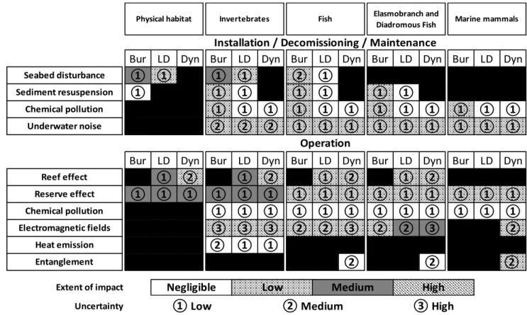
4. Environmental effects and impacts
25
Potential environmental effects associated with SPC are summarised in Figure 3. During installation,
26
maintenance and decommissioning phases, these effects may include physical habitat disturbances,
27
sediment resuspension, chemical pollution and underwater noise emission. More long-term effects may
8
occur during the operational phase, with changes in electromagnetic fields, heat emission, risk of1
entanglement, chemical pollution, and creation of artificial reef and reserve effects.
2
4.1 Habitat reworking
3
• Physical changes
4
Substratum alterations are mainly created by equipment used for cable route preparation (grapnels such as
5
in the aforementioned Pre-Lay Grapnel Run) and installation of the cable (ploughing, jetting and
cutting-6
wheels). The surface area of disturbance can be enlarged when installation techniques require large ships
7
with several anchoring stabilizers [18].
8
These methods of reworking the seabed may lead to direct destruction of benthic habitats, flora
9
and fauna. However, such effects are usually restricted to a limited area, the width and intensity of
10
disturbance, depending on the installation method. For example, the footprint of a trenching plough may
11
vary from 2 to 8 m depending on device size [5]. According to Vize et al. [20], ploughing methods seem to
12
cause less seabed disturbance than other methods. These disturbances are usually limited in time, as
13
installation works only require a few hours or days per km of cable [21]. Ploughing and jetting methods
14
favour a quicker recovery of bottom topography, as the trench is filled with displaced and re-suspended
15
material immediately after digging and cable laying. In intertidal areas, physical impacts on the substrate
16
usually occur over a larger surface area, of the order of tens of metres, due to the utilisation of vehicles such
17
as mechanical excavators (Figure 4). Alternatively, underground horizontal directional drilling (10 m below
18
the sediment surface) may be used in intertidal areas up to distances of 700-1000m, and occasionally up to
19
1800 m [18]. This installation technique only disturbs the substrate and biota locally over a few m² at the
20
land and sea entrance points.
21
Unburied cables may also cause habitat loss, but to a lesser extent than buried cables. Disturbance
22
is limited to the cable width itself, or to the dimensions of the materials used to stabilise and protect [22].
23
In shallow areas, some sections of unstabilised, unburied cables may act as dragging elements that disturb
24
the sediments due to their strumming movement induced by the swell during the operation phase [23].
25
Wave action may shift the cable, and direct interaction with the hard seafloor can result in surface scraping
26
and incisions in rock outcrops [13]. Maintenance (to a lesser extent) and/or decommissioning phases may
27
generate similar effects to those of installation, but their magnitude will depend on the duration and scale
28
(repairs vs. inspections) of the works.
9
With respect to other human activities at sea, physical disturbance to the seabed caused by cables1
is spatially limited. For example, the footprint of submarine cables in the UK coastal area is about 0.3 km2,
2
representing less than 0.01% of the coastal seabed [24], whilst in the Basque Country coastal zone (Northern
3
Spain), the footprint of cables and pipelines is about 2.3 km2, or 0.02% of the area between the coastline
4
and the exclusive economic zone [25].
5
• Biological changes
6
Substratum alterations may affect related benthic communities by direct impacts such as
7
displacement, damage or crushing of organisms. Andrulewicz et al. [10] examined the environmental
8
impact of the installation of a buried submarine power cable on soft bottoms of the Baltic Sea. They
9
concluded that there were no significant changes in benthic diversity, abundance or biomass on the cable
10
route or in its close proximity one year after the installation.
11
The magnitude and significance of biological changes depend on several factors linked to the
12
sensitivity and resilience capability of the species or communities affected. Habitat or community resilience
13
is characterised by the capacity to return to its initial ecological state after a perturbation (cabling in this
14
case), and the the duration of this response. The weaker the resilience is, the more sensitive the habitat or
15
the community. Thus resilience depends on several factors, including: the nature and stability of the
16
substratum [26–28], habitat depth [24,29] and life cycle of disturbed species (for example, seagrass
17
meadows, which grow very slowly, may take several years to recolonise a disturbed area [30]).
18
The magnitude of biological changes is also dependent on the composition of the community itself,
19
i.e., the relative occurrence of benthic species (abundance and biomass) and assemblages (richness) along
20
the cable route, compared with their occurrence at the regional scale. Due to the small spatial footprint of
21
cabling, the overall impact on benthic communities is negligible if its spatial distribution is significantly
22
homogeneous.
23
Benthic community resilience after commissioning of submarine cables remains poorly
24
understood owing to the lack of long-term studies (i.e. occurring several years). Despite the relatively small
25
spatial footprint affected by SPC operations, future studies should focus on the resilience of habitats and
26
communities of particular ecological or economic interest (e.g. sea grass, maerl beds and nursery areas).
10
4.2 Sediment resuspension1
Depending on the nature of the seafloor, sediment reworking by installation, maintenance or
2
decommissioning can lead to turbid plumes that can reach several tens of hectares, with suspended
3
particulate matter concentrations that can reach several dozen mg l-1 [31]. Apart from sediment type, the
4
extent and properties of plumes will depend on factors such as installation technique, hydrodynamic
5
conditions and the scale of cable-laying. For instance, in the Nysted offshore wind farm (Denmark) where
6
the substrate is dominated by medium sand sediment, cable installation in water depths between 6 and 9.5m,
7
generated mean particle concentrations of 14 mg l-1 (up to 75 mg l-1) at 200 m from the operation site during
8
trenching with a backhoe dredger, and 2 mg l-1 (up to 18 mg l-1) during jetting (Seacon, 2005 in [20]) .
9
Turbidity can persist for several days depending on the duration of the whole cable-laying process. At the
10
Nysted offshore wind farm, one month was necessary to excavate 17,000m3 of sediment for a 10.3-km
11
long, 1.3-m wide and 1.3-m deep cable trench [32]. However, at any given location on a cable route,
12
disturbance will typically persist from a few hours to a few days.
13
Decrease in water transparency and deposition of the resuspended material may limit light for
14
primary producers and impact feeding ability of fish that detect their prey visually [33]. The efficiency of
15
invertebrate filter-feeding could also be temporarily modified [34,35]. Resuspension/deposition processes
16
through the plume may bury the eggs of bottom laying species. The presence of mineral particles in the
17
water column may also lead to gill damage in young fish larvae [36,37]. For example, early survival of cod
18
recruits (whose eggs are pelagic) may be affected by the sediment plume created by cable trenching [38].
19
Nevertheless, turbidity increases resulting from cable installation and decommissioning constitute
20
localised and short-term effects. Although no study has focused on the impact of particle resuspension
21
induced by cable installation and decommissioning on marine communities, it should generally have
22
negligible impacts on marine ecosystems.
23
4.3 Chemical pollution
24
The main chemical risk is the potential release of sediment-buried pollutants (e.g., heavy metals and
25
hydrocarbons) during sediment re-suspension caused by cable burial, decommissioning or repair works. The
26
highest contaminant concentrations are generally located in coastal areas due to human activities. A preliminary
27
analysis to assess the level of sediment toxicity should be performed in potentially polluted areas to select a
28
cable route which avoids the remobilisation and dispersion of pollutants [39].
11
Pollution can also occur during the operation phase, especially for monopolar DC cables using sea1
electrodes for the return current path (which represent around 30% of HVDC in service use [40]). Indeed,
2
the cathode and the anode of sea electrodes release toxic electrolysis products like chlorine and bromine
3
which can impact the immediate water quality [10,40]. To a lesser extent, some older cables have
4
hydrocarbon fluid insulation and may leak contaminants into the marine environment when damaged. The
5
amount of fluid released will vary according to the time needed to detect and repair the leakage, its location and
6
the extent of the damage, but in worst cases several tens of litres can be released per hour (Schreiber et al. 2004,
7
in [41]). It should be noted that installation of oil-insulated cables ceased in the 1990s [42]. Furthermore, ships
8
and hydraulic equipment pose a higher potential risk of accidental oil leakage during operations [23,43].
9
Cables also include copper, lead and other heavy metals that are potential sources of contamination. For
10
example, a cable consisting of a 3.5-mm lead sheath contains 12 kg lead m-1 (Schreiber et al., 2004 in [41]).
11
Heavy metals can potentially dissolve and spread into the sediment from damaged and abandoned cables, but
12
the quantities released are considered insufficient to have significant impacts. Furthermore, such pollution
13
is rare as cables are usually removed when no longer in operation. Although no studies focus specifically on
14
SPC-related contaminants, this source of disturbance is considered to be rare, spatially localised and unlikely
15
to have significant impacts on benthic communities.
16
4.4 Underwater noise
17
Anthropogenic noise can be produced during route clearance, trenching and backfilling, cable and
18
cable protection introduction by the vessels and tools used during these operations. Intensity and
19
propagation of underwater noise will vary according to bathymetry, seafloor characteristics (e.g., sediment
20
type and topography), vessels and machines used, and water column properties. In-situ data on such noise
21
is scarce, and modelling approaches have been used to estimate the sound pressure levels (SPL) expected
22
during installation. Nedwell and Howell [44] examined the noise produced by plough trenching in a sandy
23
gravel area for the installation of an electric cable within a Welsh offshore wind farm. Results showed a
24
maximal noise emission of 178 dB re 1μPa (on a frequency range from 0.7 to 50 kHz) at 1 m from the
25
trenching area. A similar study by Bald et al. [45] focused on noises from trenching and cable installation
26
of a wind-farm platform in a sandy area in the Bay of Biscay. During the installation phase, average sound
27
level was 188.5 dB re 1μPa (at 11 kHz) at 1m from the source. Modelling using these in situ data estimated
28
that the underwater noise would remain above 120 dB re 1μPa in an area of 400 km² around the source.
12
Another, albeit lesser, noise emission caused by submarine cables comes from vibrations during1
operation of several kinds of HVAC (High Voltage Alternating Current) cables because of the Coulomb
2
force occurring between conductors [46]. For example, a 138 kV transmission cable situated in Canada
3
emits a SPL, for the 120 Hz tonal vibration, of approximately 100 dB re 1 Pa at 1 m [47]. Compared to
4
cable installation, such SPL is low, but continuous because it occurs during the whole operation phase.
5
There is no clear evidence that underwater noises emitted during cable installation affect marine
6
mammals or any other marine animal, although it is accepted that many marine animals (notably mammals
7
and fishes) detect and emit sounds for different purposes such as communication, orientation or feeding.
8
Marine mammals have high frequency functional hearing ranges from 10 Hz to 200 kHz [48], while fish
9
typically hear at much lower frequencies, often from 15 Hz to 1 kHz [49]. Other taxa, organisms including
10
sea turtles [50,51] and many invertebrates such as decapods [52], cephalopods [53,54] or cnidarians [55]
11
have also been shown to be sound-sensitive. Many studies highlight the reaction of cetaceans to
12
anthropogenic sounds of different intensities [56,57]. Sounds generated by ship activity can impact the
13
behaviour of different fish species [58,59]. Anthropogenic underwater noise can affect marine life in
14
different ways, by inducing species to avoid areas, disrupting feeding, breeding or migratory behaviour,
15
masking communication and even causing animal death [60]. So far, characterisation of acoustic thresholds
16
causing temporary or permanent physical damage are much better described for marine mammals [61,62],
17
than for fish [63], and remain unknown for marine invertebrates and sea turtles [64].
18
Compared with other anthropogenic sources of noise, such as sonar, piling or explosions,
19
underwater noise linked to undersea cables remain low. Cable installation is a spatially localised temporary
20
event, so the impact of noise on marine communities is expected to be minor and brief. HVAC cable
21
vibration, although significantly lower than potential SPL during the installation phase, requires special
22
attention though because its long-term impacts remain unknown.
23
4.5 Reef effect
24
Like other immersed objects (e.g. shipwrecks, oil/gas platforms, and MRE devices) unburied
25
submarine cables and associated protection/stabilisation can create artificial reefs, inducing the so-called
26
‘reef’ effect [65]. Artificial reefs have been commonly used for centuries to enhance fisheries, and more
27
recently for habitat rehabilitation or coastal protection [66]. These structures are colonised by hard-substrate
13
benthic species including epifauna and mobile macrofauna, and may also attract mobile megafauna, such1
as decapods or fishes.
2
The extent of the reef effect depends on the size and nature of the cable protection structure, but also
3
the characteristics of the surrounding area and native populations [65]. Such artificial structures are
4
expected to have limited reef effects when located within a naturally hard substratum environment. For
5
example, Sherwood et al. [14], looking at the effects of laying and operating the BassLink HVDC cable,
6
found that, 3.5-years after the cable installation, the benthic sessile community present on the half-shell
7
cover was similar to the surrounding basalt reef area (Figure 5.A). Similar investigations showed no
8
significant differences between communities on powered cables and hard bottom control areas [9,12,67].
9
By contrast, on soft sediments, unburied cables generate a stronger reef effect and host a new community,
10
as illustrated by the unburied sections of the ATOC/Pioneer cable (Half Moon Bay, California) colonised
11
by actinarians [13]. In this case, sea anemones became more abundant on the cable than on the surrounding
12
soft bottom 8 years after cable installation (Figure 5.B) and fish species were more abundant close to the
13
cable, probably in response to increased habitat complexity compared with the surrounding environment.
14
‘Reef effect’ is usually considered to be a positive anthropogenic impact, as artificial reefs generally
15
have higher densities and biomass of fish and decapod crustaceans than surrounding soft bottoms. Also,
16
when associated with a fisheries exclusion area (as described in section 4.6), artificial reefs may function
17
as refuges for these populations, with potential spill-over benefits for adjacent stocks and fisheries [68].
18
This is particularly true for commercial species, like the European lobster (Homarus gammarus) or edible
19
crab (Cancer pagurus) observed on offshore wind-farm foundations [69,70]. In some cases, the cable reef
20
effect is considered a compensatory measure for habitat destroyed during cable installation [65].
21
Concerning dynamic cables used to connect offshore floating MRE projects, in addition to the processes of
22
colonisation and concentration, biofouling can significantly increase cable weight and wear at least on the
23
first tens of metres, creating technical problems [71].
24
On the other hand, reef effect may potentially result in long-term negative effects if the structures
25
facilitate the introduction of non-indigenous sessile species. Indeed, the number of non-native species
26
present on new hard artificial substrate can be 2.5 times higher than on natural substratum [72]. Thus, the
27
presence of a new hard substratum, such as a cable or its protection structures, on soft sediment can
28
potentially open a corridor to a new area for some hard-bottom sessile species. Such processes can
14
potentially lead to the spread of new introduced species by a stepping stone process across biogeographical1
boundaries [73]. Although cable routes are narrow and often buried in areas of soft sediment, and no spread
2
of invasive species caused by SPC has been documented, this question needs to be considered in light of
3
the exponential growth of offshore wind farms.
4
4.6 Reserve effect
5
The potential reserve effect of SPC is linked to the limitation/interdiction by local authorities of
6
environmentally damaging human activities (trawl fishing, anchoring, dredging, etc.) around the cable route
7
during the operation phase and is considered as a positive effect for ecosystems. In some cases, the use of
8
passive fishing equipment (nets, lines, and traps) is permitted, reducing the protection of targeted species.
9
The size of the protected zone and the level of restriction depend on the cable installation method (buried
10
or unburied), the number of cables present in the area, and the size of the electrical connections. For
11
example, the Cook Strait cables have an extensive protected area to prevent damage to three submarine
12
HVDC cables and one fibre-optic cable which link the North and South Islands of New Zealand over 40
13
km. An area seven kilometres wide around these cables, where anchoring and fishing of any type are
14
prohibited, was created by New Zealand authorities, corresponding to a marine protected area of
15
approximately 236 km² (Figure 6; [74]).
16
With fishing access restricted, economically exploited sedentary species (such as scallops or clams)
17
will be protected throughout their lives, but protection of mobile species (such as fish) will only be effective
18
during the time they live in/pass through the cable area. A study focusing on fish found no significant
19
differences in species richness inside and outside a protection zone [75]. The reserve effect has been clearly
20
demonstrated for some commercial offshore wind farms, including their associated electric cable grids.
21
Within the Dutch offshore wind farm Egmond aan Zee, where all nautical activities are prohibited, the
22
habitat heterogeneity [76], benthic biodiversity and possibly the use of the area by the benthos, fishes,
23
marine mammals and some bird species have increased (although counterbalanced by a decreasing use of
24
several other bird species). These changes occurred during the first two years of wind-farm operation, in
25
response to the establishment of the marine protected area but also other factors, such as the reef effect of
26
the wind turbine foundations, rockfill and cables. Nenadovic [77] studied a protected area associated with
27
a fibre-optic cable route on the coast of the Gulf of Maine (USA) and showed a significant difference in
28
epifaunal community structure between protected and unprotected areas. In particular, engineer species
15
were more frequent near the cable route. The maintenance of such species with a complex biological1
structure highlights the structuring effect of marine protected areas.
2
4.7 Electromagnetic fields
3
The potential ecological impacts of electromagnetic fields (EMF) are of particular concern. EMF
4
are generated by current flow passing through power cables during operation and can be divided into
5
electric fields (called E-fields, measured in volts per metre, V m-1) and magnetic fields (called B-fields,
6
measured in μT). Electric fields increase in strength as voltage increases and may reach 1000 μV m-1 for an
7
electric cable [78], but are generally effectively confined inside cables by armouring. EMF characteristics
8
depend on the type of cable (distance between conductors, load balance between the three phases in the
9
cable, etc.), power and type of current (direct vs. alternating current – AC generates an alternating magnetic
10
field which creates a weak induced electric field of a few μV m-1, called an iE-field, near the cable), and
11
whether it is buried or not [8,79]. When the cable is buried, the sediment layer does not entirely eliminate
12
the EMF, but reduces exposure to the strongest EMF existing in direct contact with the cable [80]. The
13
strength of both magnetic and induced electric fields increases with current flow and rapidly declines with
14
distance from the cable [81].
15
Electric currents with intensities of 1600 A are common in submarine cables. In response,
16
magnetic fields of approximately 3200 μT are generated, decreasing to 320 μT at 1 m distance, 110 μT at
17
4 m and values similar to the terrestrial magnetic field (50 μT) beyond 6 m [82]. By contrast, according to
18
AWATEA [83], a standard submarine cable carrying 132 kV AC (350 A) generates a magnetic field of 1.6
19
μT on the “skin” of the cable (i.e., within millimetres), while cables carrying 10-15 kV DC do not generate
20
a significant magnetic field beyond a few centimetres from the cable surface. The magnetic field varies
21
greatly as a function of the cable type, and modelling of the magnetic field induced by either DC (Figure
22
7.A) or AC cables (Figure 7.B) reveals this heterogeneity (1 to 160 μT at the cable surface; [81]). Particular
23
attention must be paid to monopolar DC cables using sea electrodes for the return current path, the design
24
of which leads to higher magnetic and electric fields [40,81]. Although modelling presents serious
25
limitations in the understanding of ecosystem-scale responses to such disturbances, the rare in-situ EMF
26
studies available for review yielded values of measured EMF comparable to those calculated by modelling
27
[10,14].
16
Many marine species around the world are known to be sensitive to electromagnetic fields,1
including elasmobranchs (rays and sharks), fishes, mammals, turtles, molluscs and crustaceans. Indeed, the
2
majority of these taxa detect and utilize Earth’s geomagnetic field for orientation and migration [84–88].
3
Some are electrosensitive, like elasmobranchs, which are able to detect E-fields and iE-fields through
4
specific organs called ampullae of Lorenzini [89,90]. This electrosense can be used to detect electric fields
5
emitted by prey, conspecifics or potential predators, as well as for orientation [90]. A few incidents of bites
6
observed on unburied SPC may also be linked to the electric field emitted by cables.
7
Thus, SPC can possibly interact in a negative way with sensitive marine species, especially benthic
8
and demersal organisms through:
9
• effects on predator/prey interactions,
10
• avoidance/attraction and other behavioural effects,
11
• effects on species navigation/orientation capabilities,
12
• and physiological and developmental effects.
13
Elasmobranchs can detect very low electric fields( starting from 0.005 μV cm-1 [81]), and magnetic (20─75
14
µT [82,86]). Power cables inducing a strong electric field can repel many elasmobranch species, preventing
15
some movement between important areas (such as feeding, mating and nursery areas). As part of the
16
COWRIE (Collaborative Offshore Wind energy Research Into the Environment) project, Gill et al. [91]
17
reported that elasmobranchs are attracted by electric fields generated by DC between 0.005 and 1 µV cm-1,
18
and repelled by electric fields of approximately 10 µV cm-1 and higher. Mesocosm studies (COWRIE
19
project) on impacts of EMF emitted by submarine cables on several elasmobranch species showed that the
20
response was not predictable and seemed to be species specific, maybe even specific to individuals [92].
21
Teleosts, especially diadromous fish, also use natural EMF to migrate. Westerberg and Lagenfelt [16]
22
showed that the swimming velocity of European eel (Anguilla anguilla) slightly decreased when crossing
23
the electromagnetic field of a non-buried 130 kV cable, but did not report evidence of population-scale
24
impact. Furthermore, no substantial impacts have been shown on physiology or survival of these taxa
25
[93,94].
26
Concerning invertebrates, data are scarce except for a few studies relating to minor or
non-27
significant impacts of anthropogenic electromagnetic fields on benthic invertebrates [15,17,93,95,96].
28
However, a recent experimental study performed by Hutchison et al. [97], highlights a subtle change in the
17
behavioural activity of the American lobster (Homarus americanus) when exposed to EMF from a HVDC1
cable.
2
Another noteworthy issue is that substantial data gaps exist between the interaction of pelagic
3
species (like pelagic shark, marine mammals or fishes) and dynamic cables. These gaps remain partly owing
4
to difficulties in evaluating impacts at population scale around these deployments.
5
4.8 Heat emission
6
When electric energy is transported, a certain amount is lost as heat by the Joule effect, leading to
7
an increase in temperature at the cable surface and a subsequent warming of the immediate surrounding
8
environment [98]. Constant water flow around a laid-down or a dynamic cable tends to dissipate thermal
9
energy and confines it to the cable surface [18]. However, for buried cables, thermal radiation can
10
significantly warm the surrounding sediment in direct contact with the cable, even at several tens of
11
centimetres away from it, and especially in the case of cohesive sediments [99]. Heat emission is higher in
12
AC than DC cables at equal transmission rates. Heat emission can be modulated by physical characteristics
13
and electrical tension of the cable, burial depth, bottom type (thermal conductivity, thermal resistance, etc.)
14
and physical characteristics of the environment [19,98,99].
15
Despite the evidence for thermal radiation from subsea cables, very few studies exist on the subject
16
and most consist of numerical modelling [18,100]. One of the rare field measurement studies concerned the
17
offshore wind array of Nysted (maximal production capacity of about 166 MW), in the proximity of two
18
AC cables of 33 and 132 kV buried in a medium sand area, approximately 1m deep. Results showed a
19
maximal temperature increase of about 2.5 ºC at 50 cm directly below the cable [41]. Transposition of these
20
results to other locations is difficult, considering the large number of factors impacting thermal radiation,
21
and other field studies are necessary to gain a better understanding of thermal radiation effects.
22
Temperature increases near the cable can modify chemical and physical properties of the
23
substratum, such as oxygen concentration profile (redox interface depth) and, indirectly, the development
24
of microorganism communities and/or bacterial activity. Physiological changes in benthic organisms living
25
at the water-sediment interface and in the top sediment layers can also potentially occur [19,101].
26
Temperature radiation can potentially cause small spatial changes in benthic community structure by way
27
of migratory behaviour modification with cryophilic species being excluded from the cable route in favour
28
of other, more tolerant species.
18
To our knowledge, the impacts of local temperature increase caused by electric cables on benthic1
communities (macrofauna diversity or microbial structure and functioning) have rarely been examined, and
2
in-situ investigations are lacking. Furthermore, studies using controlled temperature increases are often
3
unrealistic regarding the extent of suspected warming. This considerable knowledge gap prevents drawing
4
conclusions about ecological impacts of long-lasting thermal radiation on ecosystems, but considering the
5
narrowness of the corridor and the expected weakness of thermal radiation, impacts are not considered to
6
be significant. Nevertheless, new field measurements and experiments are required to fully understand this
7
phenomenon under operational conditions and to assess its impacts on potentially exposed organisms.
8
4.9 Entanglement risks
9
Before the 1960s, entanglement of mobile megafauna with cables occurred during the operation phase
10
leading, in the worst cases, to lacerations, infections, starvations and drowning of the trapped marine
11
mammals [102]. Technical improvements made since the 1960s for installation of laid-down cables have
12
reduced this risk [3]. Currently, entanglement risks only concern dynamic SPC. Although this risk is
13
considered to be non-significant, concerning a single dynamic SPC (such as pilot scale projects still under
14
development), it may require more attention in the future owing to the growth in commercial farms of
15
floating devices and associated webs of dynamic SPC and mooring lines hanging in the water column.
16
According to Kropp [103], arrays of dozens of dynamic cables and mooring lines per km² can potentially
17
affect large marine animals, i.e. whales.
18
According to existing reports, entanglements caused by dynamic SPC will remain a low risk [103,104].
19
The large diameters of SPC (>5 cm) make them relatively inflexible [105], and mooring lines and dynamic
20
SPC should be tight enough to reduce entanglement [103]. However, indirect entanglement resulting from
21
discarded fishing gear wrapped around dynamic SPC [102] may significantly impact a larger set of species,
22
including marine mammals, sharks or fishes. Quantifying such risks will only be possible when floating
23
MRE installations are operational. Consequently, entanglement risk remains highly speculative at this
24
stage, relying on modelling data..
25
5. Recommendations
26
5.1 Mitigation and compensation measures
27
Potential environmental impacts of cables should be anticipated prior to the installation phase by
28
applying avoidance and reduction measures. In order to mitigate potential environmental disturbances
19
caused by cabling activity, measures exist and should be applied, including the choice of an appropriate1
cable route and installation technique, answering the following:
2
• Planning the cable route to avoid impacts on habitats and benthic species that are most sensitive to
3
disturbance or are of special ecological interest (with special attention to slow-growing long-lived
4
species). Particularly important and sensitive habitats in the North Atlantic include biogenic reefs
5
comprising Modiolus modiolus (Horse mussel beds), Sabellaria spinulosa (honeycomb worm), maerl
6
beds and Zostera seagrass meadows.
7
• Selecting landing zones and cable routes in order to prevent the re-mobilisation of contaminants present
8
in sediments and contamination of the trophic food web.
9
• Using cable technology suitable for reducing the emission of magnetic fields, such as three-phase AC
10
cables and bipolar HVDC transmission systems [39], and minimising the emission of directly
11
generated electric fields through adequate shielding [44].
12
• Avoiding the use of monopolar DC cables using sea electrodes, which produce toxic compounds,
13
generate higher EMF and accelerate corrosion of manmade structures, in favour of cable systems with
14
other return path options causing less disturbance [40].
15
• Deploying dynamic SPC with the lowest risks of entanglement for marine megafauna where relevant.
16
Appropriate configurations, as for mooring lines [104], and appropriate cable type, with diameters and
17
colours allowing visual tracking of affected species [103].
18
• Managing installations with respect to life cycles of mobile species (winter dormancy, migration,
19
mating and/or spawning, etc.), and to avoid disturbance of sensitive species (e.g., fish, crustaceans,
20
marine mammals, marine turtles or resting/feeding birds).
21
• Prioritizing burial depth appropriate to the substratum type. To reduce exposure of sensitive species to
22
electromagnetic fields and heat emission, the physical distance between animals and the cable can be
23
increased. According to models proposed by Normandeau et al. ([81], Figure 7), the EMF level at the
24
water-sediment interface with a 2m burial depth would be approximately 25% of its initial value-
25
versus 60% for a 1m burial depth.
26
• Prioritizing the laid-down option rather than burying in the presence of unavoidable fragile benthic soft
27
bottom habitats (e.g., seagrass beds; [11]).
20
• Installing devices with a strategy to reduce electrical connections and limiting the number of export1
cables (i.e., when several MRE projects are present in close proximity).
2
To complement reduction and avoidance strategies, compensation measures should be considered if
3
residual impacts persist. In this event, and only after having addressed mitigation options, compensation
4
measures may be applied directly to the implantation site, or in close proximity. Discussions between
5
stakeholders are recommended to establish parameters for scale and responsibilities for compensation
6
measures.
7
A possible form of compensation measures can consist of improving future engineering strategies
8
through experimental studies of ecosystem functioning and resilience following disturbance. For example,
9
on the Paimpol-Bréhat French tidal turbine test site, the cable route connecting turbines to the land crosses
10
important seagrass meadows containing Zostera noltei and Z. marina. In response, the prime contractor
11
(EDF, Electricité De France) developed an experimental protocol aiming to transplant some seagrass plants
12
located on the route area to another barren place before cable burial. Such measures aimed to test
13
transplantation techniques and acquire knowledge about the mechanism of recolonisation by seagrass after
14
installation of a cable [106]. Similar transplantation experiments are currently being tested in the context
15
of SPC installation (e.g., ongoing project by Red Eléctrica de España in Majorca and Ibiza).
16
Environmental monitoring strategies performed in parallel with cable installation should: (i) verify the
17
impact predictions made in the environmental impact study and detect unforeseen alterations, (ii) ensure
18
the fulfilment of mitigating measures proposed, and (iii) provide data to improve future environmental
19
impact assessments and installation plans [107].
20
5.2 Future research priorities
21
A hierarchical model of potential impacts based on the expected levels of ecological effects and
22
the associated levels of scientific knowledge (or uncertainty) is presented in table 2. This synthetic output
23
corresponds to a concerted expert judgement of the authors, and takes into account the main conclusions of
24
the literature cited in this paper. The main priorities concern benthic habitat disturbance, reef and reserve
25
effects and potential impacts of EMF. A substantial data gap remains concerning the impacts of EMF
26
because data on sensitivity thresholds or tolerance are only available for a small number of taxa. Major
27
uncertainties therefore remain for several large groups (cetaceans, pinnipeds, fishes, crustaceans, and many
28
pelagic species) [81]. Better knowledge of the different sensitivity thresholds is needed to fill these data
21
gaps, especially for several key species at different stages of their development. Additionally,1
environmental issues may arise following industrial-scale deployment of MRE devices using multiple
2
submarine electric cables installed in close proximity and creating a network impacting a large area. The
3
cumulative effects of more than one activity or perturbation factor, which may act in synergy, must be
4
considered [108]. For example, recovery of benthic communities after cable installation may be slower and
5
less efficient if the benthic ecosystem is already threatened by other anthropogenic disturbances such as
6
chemical pollution, eutrophication, or invasive species (especially in enclosed and shallow areas). The
7
assessment of impacts due to interactions between different kinds of disturbances remains highly
8
speculative, partly since environmental impacts of single cables are still poorly understood.
9
6. Conclusions
10
Although SPC have been used since the mid-19th century, environmental concerns associated with
11
their installation and operation are much more recent. This is due to an increased awareness of
12
anthropogenic impacts, the rapid expansion of SPC deployments, and the growing demand for electric
13
interconnections between countries that have adopted a common energy strategy.
14
The main potential environmental impacts associated with SPC during their operational phase are those
15
related to the production of electromagnetic fields, the creation of artificial reefs and “reserve effects”
16
caused by the interdiction of certain human activities. Cable installation, maintenance and decommissioning
17
also impact the environment, causing direct benthic habitat modification, which can be especially
18
problematic in the case of sensitive bioconstructed habitats. These phases of SPC may also induce
19
significant particle and pollutant resuspension events in very confined and modified shallow coastal areas.
20
Mitigation measures are possible before, during or after projects to limit the ecological impacts of SPC and
21
associated maritime operations.
22
While potential environmental impacts generated by SPC are recognised, better knowledge of amplitude
23
and duration is essential. Generally these disturbances occur over short times scales, creating relatively
24
minor impacts on ecosystem structure and functioning. Nevertheless, the nature and amplitude of certain
25
impacts remain poorly studied, particularly the EMF impacts on elasmobranchs, diadromous fishes and
26
invertebrates, and assessment of cumulative impacts. Despite these knowledge gaps, the present review
27
provides a quantification and ordering of the different impacts of SPC on marine environments and offers
28
updated practical recommendations for developer mitigation strategies.
22
1
Acknowledgements
2
This work is the result of a collaborative effort between authors of the paper sponsored under EERA
3
(European Energy Research Alliance), UKCMER (UK Centre for Marine Energy Research), Région
4
Bretagne and the National Research Agency under the Investments for the Future program bearing the
5
reference ANR-10-IED-0006-17. The authors would like to thank Normandeau Associates Inc., Louis
6
Dreyfus Travocean, the Monterey Bay Aquarium Research Institute, John Sherwood and collaborators as
7
well as Olivier Dugornay for their kind assistance in supplying the different photography and figures. We
8
also thank three anonymous reviewers for constructive criticism and valuable suggestions. Finally, the
9
authors would also like to thank Nolwenn Quillien, Julie Lossent, Guillaume Damblans and Kelly Cayocca
10
for their help.
11
23
References1
[1] Ardelean M, Minnebo P. HVDC Submarine Power Cables in the World. State-of-the-Art
2
Knowledge; EUR 27527 EN. 2015. doi:10.2790/95735.
3
[2] Boehlert GW., Gill AB. Environmental and Ecological Effects Of Ocean Renewable Energy
4
Development. Oceanography 2010;23:68–81. doi:10.5670/oceanog.2010.46.
5
[3] Wood MP, Carter L. Whale entanglements with submarine telecommunication cables. IEEE J
6
Ocean Eng 2008;33:445–50. doi:10.1109/JOE.2008.2001638.
7
[4] International Cable Protection Committee. Submarine Cables and BBNJ. 2016.
8
[5] Carter L, Burnett D, Drew S, Marle G, Hagadorn L, Bartlett-McNeil D, et al. Submarine Cables
9
and the Oceans – Connecting the World. UNEP-WCMC Biodivers Ser 2009;31.
10
[6] Edenhofer O, Pichs‐Madruga R, Sokona Y, Kristin S, Matschoss P, Kadner S. Summary for
11
Policymakers. In: IPCC Special Report on Renewable Energy Sources and Climate Change
12
Mitigation, Cambridge: Cambridge University Press; 2011.
13
[7] Lindeboom H, Degraer S, Dannheim J, Gill AB, Wilhelmsson D. Offshore wind park monitoring
14
programmes, lessons learned and recommendations for the future. Hydrobiologia 2015;756:169–
15
80. doi:10.1007/s10750-015-2267-4.
16
[8] Copping A, Sather N, Hanna L, Whiting J, Zydlewsk G, Staines G, et al. Annex IV 2016 State of
17
the Science Report: Environmental Effects of Marine Renewable Energy Development Around the
18
World 2016. doi:10.1097/JNN.0b013e3182829024.
19
[9] Dunham A, Pegg JR, Carolsfeld W, Davies S, Murfitt I, Boutillier J. Effects of submarine power
20
transmission cables on a glass sponge reef and associated megafaunal community. Mar Environ
21
Res 2015;107:50–60. doi:10.1016/j.marenvres.2015.04.003.
22
[10] Andrulewicz E, Napierska D, Otremba Z. The environmental effects of the installation and
23
functioning of the submarine SwePol Link HVDC transmission line: A case study of the Polish
24
Marine Area of the Baltic Sea. J Sea Res 2003;49:337–45. doi:10.1016/S1385-1101(03)00020-0.
25
[11] Bacci T, Rende SF, Nonnis O, Maggi C, Izzi A, Gabellini M, et al. Effects of laying power cables
26
on a Posidonia oceanica (L.) Delile prairie: The study case of Fiume Santo (NW Sardinia, Italy). J
27
Coast Res 2013;65:868–73. doi:10.2112/SI65-147.
28
[12] Love MS, Nishimoto MM, Clark S, Mccrea M, Bull AS. The Organisms Living Around Energized
24
Submarine Power Cables , Pipe , and Natural Sea Floor in the Inshore Waters of Southern1
California. Bull South Calif Acad Sci 2017;116:61–87.
2
[13] Kogan I, Paull CK, Kuhnz LA, Burton EJ, Von Thun S, Gary Greene H, et al. ATOC/Pioneer
3
Seamount cable after 8 years on the seafloor: Observations, environmental impact. Cont Shelf Res
4
2006;26:771–87. doi:10.1016/j.ejor.2004.05.021.
5
[14] Sherwood J, Chidgey S, Crockett P, Gwyther D, Ho P, Stewart S, et al. Installation and operational
6
effects of a HVDC submarine cable in a continental shelf setting: Bass Strait, Australia. J Ocean
7
Eng Sci 2016;1:337–53. doi:10.1016/j.joes.2016.10.001.
8
[15] Love MS, Nishimoto MM, Clark S, Bull AS. Identical Response of Caged Rock Crabs (Genera
9
Metacarcinus and Cancer) to Energized and Unenergized Undersea Power Cables in Southern
10
California, USA. Bull South Calif Acad Sci 2015;114:33–41. doi:10.3160/0038-3872-114.1.33.
11
[16] Westerberg H, Lagenfelt I. Sub-sea power cables and the migration behaviour of the European eel.
12
Fish Manag Ecol 2008;15:369–75. doi:10.1111/j.1365-2400.2008.00630.x.
13
[17] Love MS, Nishimoto MM, Clark S, McCrea M, Bull AS. Assessing potential impacts of energized
14
submarine power cables on crab harvests. Cont Shelf Res 2017;151:23–9.
15
doi:10.1016/j.csr.2017.10.002.
16
[18] Worzyk T. Submarine Power Cables: Design, Installation, Repair, Environmental Aspects. Power
17
Syst 2009;39. doi:10.1007/978-3-642-01270-9.
18
[19] OSPAR Commission. Background document on potential problems associated with power cables
19
other than those for oil and gas activities. 2008.
20
[20] Vize S, Adnitt C, Stanisland R. Review of cabling techniques and environmental effects applicable
21
to the offshore wind farm industry (BERR Technical Report). 2008.
22
[21] Rees J, Larcombe P, Vivian C, Judd A. Scroby Sands Offshore Wind Farm – Coastal Processes
23
Monitoring . Final Report. 2006.
24
[22] Wilhelmsson D, Malm T, Thompons R, Tchou J, Sarantakos G, McCormick N, et al. Greening
25
Blue Energy : Identifying and managing the biodiversity risks and opportunies of offshore
26
renewable energy. IUCN; 2010.
27
[23] Bald J, Campo A, Franco J, Galparsoro I, Gonzalez M, Liria P, et al. Protocol to develop an
28
environmental impact study of wave energy converters. Rev Investig Mar 2010;17:62–138.