HAL Id: hal-02270271
https://hal.archives-ouvertes.fr/hal-02270271
Submitted on 24 Aug 2019
HAL is a multi-disciplinary open access archive for the deposit and dissemination of sci-entific research documents, whether they are pub-lished or not. The documents may come from teaching and research institutions in France or abroad, or from public or private research centers.
L’archive ouverte pluridisciplinaire HAL, est destinée au dépôt et à la diffusion de documents scientifiques de niveau recherche, publiés ou non, émanant des établissements d’enseignement et de recherche français ou étrangers, des laboratoires publics ou privés.
A Process Model Driven Approach Applied in
TOPCASED for Embedded Real-Time Software
Angel Garcia, Benoit Combemale, Xavier Crégut, Jean-Nol Guyot, Boris
Libert
To cite this version:
Angel Garcia, Benoit Combemale, Xavier Crégut, Jean-Nol Guyot, Boris Libert. A Process Model Driven Approach Applied in TOPCASED for Embedded Real-Time Software. Embedded Real Time Software and Systems (ERTS2008), Jan 2008, Toulouse, France. �hal-02270271�
TOP
PROCESS
A Process Model Driven Approach Applied in
TOPCASED for Embedded Real-Time Software
Angel Garcia1, Benoît Combemale2, Xavier Crégut2 Jean-Nol Guyot1,2 Boris Libert1,2 1: Tectosages, Parc Technologique Delta Sud Cap Delta, 09340 Verniolle, France
2: IRIT – University of Toulouse, 2 rue Charles Camichel, 31071 Toulouse cedex 7, France [email protected]
Abstract—In this paper we present the work under-taken in the context of the TOPCASED R&D project (Toolkit in OPen source for Critical Applications & SystEms Development), which aims at providing an open source toolkit for the development of critical applications (embedded, real-time) and systems. The TOPCASED project defines quality requirements that must be ensured in the process used for the construction of its tools. The contribution of this paper consists in a method that 1) verify that a process respects these quality requirements and 2) verify the termination property of the process according to expressed con-straints (scheduling, resource, time).
Respect of quality requirements is achieved by explic-itly modelling what parts of the process cover which requirements. Models are based on OMG SPEM2.0 metamodel and may be defined using the Eclipse Process Framework (EPF).
To achieve verification of process models, we trans-late process models into equivalent Petri net models, and properties on the process into LTL (Linear Tem-poral Logic) formulae on the Petri net model. We then use the Tina toolkit (TIme petri Net Analyzer) and in particular its model-checker to check whether the properties hold.
1. Introduction
The TOPCASED R&D project (Toolkit in OPen source for Critical Applications & SystEms Develop-ment)1 aims at providing an open source toolkit for the development of critical applications (embedded, real-time) and systems. The TOPCASED toolkit is an Eclipse-based platform whose purpose is to integrate new tools (e.g models editors, simulators, verifica-tion tools, generators of code, documentaverifica-tion...). The TOPCASED project defines quality requirements that
1
http://www.topcased.org
must be ensured in the process used for the construc-tion of these tools. The contribuconstruc-tion of this paper consists in a method that 1) verify on a process the respect of these quality requirements and 2) verify the termination property of the process.
To check the respect of quality requirements, it is necessary on the one hand to model all of them and on the other hand to model the development process itself. Then, our approach consists in 1) specializing each requirement defined and 2) making sure that all requirements are well specialized within the defined process. This approach was applied not only to qual-ity requirements specific to the TOPCASED project but also to the CMMI (Capability Maturity Model Integration) process improvement approach.
These modellings are carried out using SPEM2.0 OMG standard (Software Process Metamodel Engi-neering). We used the Eclipse plug-in called EPF (Eclipse Process Framework) which is dedicated to process modelling and which conforms to SPEM2.0. Once the process defined, it is necessary to be able to check its feasibility according to the constraints expressed (scheduling, resource, time). Our approach consists in analysing the process model termination by model-checking. For this purpose, we map process models into Petri nets models and process properties into LTL (Linear Temporal Logic) formulae. We use the Tina toolkit (TIme petri Net Analyzer) and in particular its model-checker.
We conclude the article with some perspectives of this work.
2. Motivation and Background 2.1 The needs for computers to assist design
For a long time now, professional have been used to rely on computer-based tools to design their systems.
As an example, the architect Sir Norman Foster did not designed the VIADUCT OFMILLAU2on sheets of paper. The same holds for the architects of the biggest towers which exist in the world today. Even the architects who draw our houses today use computers. We can also consider the aerospace domain, a not so old one and, in particular the FALCON7X3 which is the up-market executive jet of the Dassault Aviation company. It is the first aircraft in the world to have been completely developed by means of numeric tech-nologies thanks to the new software tools created by the Dassault Systems company. The whole aircraft has been virtually designed, without requiring the building of prototypes. The main benefits of this approach is to reduce the time to market, in that case from 14 months to only 7 months. Furthermore, the tests in flight only concern the most critical phases.
It may not only be considered as an improvement or just an evolution, it implies big changes in the tech-nologies used and in the organization that will impact the whole production line. The software industry is experiencing these turnovers today and arrives at the age of maturity. It becomes industrialized and it has too, to design both its own products and the processes of production of those products.
2.2 Model-Driven Engineering
After the technologies of objects and components, the MODEL-DRIVEN ENGINEERING4approach is tak-ing more and more importance over the last years and implies changes in the process management and its improvement. To face the increasing complexity of the systems to build, the notions of model and meta-models are at the center of new systems as they allow to gain on abstraction by focusing on domain specific notions through DSL (Domain Specific Languages) and allow to capitalize knowledge in the tools that manipulates those DSL. Tools that are used in MDE technologies deal with modeling and transformation (transformation also includes code or documentation generation) that may be used to model the system, build it, make some verification on it or simulate it.
In this new vision, the approach for developing enterprise applications is note code-centric but based on models. Numerous models (of profession, test, architecture, display, process, etc.) existing, are devel-oped, informed and maintained except the code and
2 http://www.leviaducdemillau.com 3http://www.generation-nt.com/ falcon-7x-avion-ordinateur-actualite-24281.html 4http://planet-mde.org; http://www.model-drivenengineering. com
the usual textual documentations. The model is not any more an element of documentation but a basic element of the production of the system.
In our profession, computing software, our models are not very "sexy". We are far from a modeling in three dimensions with simulation, as they exist in the professions by the building business or by the mechanical engineering. Because our material is nu-meric and already represents an abstraction, a model, of the real world. We also speak about technological space. But to stay in the same technological space also presents important perspectives. Because if Falcon 7X is completely digitized, it is necessary to make it on base of metals, electronics or dissimilar materials. In data processing the chain is numeric: from the design to the production.
2.3 Design of domain processes
MDE could and should also be applied to the def-inition, management and improvement of processes. The aims are the same as in software development, that is the capitalization of knowledge and the lever-age of the level of abstraction.
But why to change our way of working?
Figures given by the manufacturers who operated this break are eloquent, but it is still difficult to con-vince the management staffs either at the enterprise level or even at the state or country level. In everyday life, management staffs are confronted to problems for which the modelling of process could bring a simple, effective, and durable answer.
Because it is not any more a question of making a audit, a snapshot of business, but of supplying to you the technical and organizational means to master your processes and improve them for your production. These needs express themselves in a sometimes very different way:
• "We do not really know who makes what!"
• "Our projects do not improve!"
• "We have excellent know-how but thzy are not spread!"
• "And what about the know-how of our seniors? Because solving these problems is not only a wish but is mandatory, it is required to put a strong impulse to your strategy and to implement the means of being successful:
• "I want a clear and global vision of the things!";
• "We have to industrialize our processes!";
• "Let us have simple and effective means to be more innovative!";
• "Let us formalize our strategy and let us com-municate!".
If you want to give a global efficiency to your processes, then it’s time to change...
2.4 The SPEM2.0 OMG’s Standard
SPEM2.0 is the OMG’s standard dedicated to soft-ware process modeling. It aims at providing orga-nizations with means to define a conceptual frame-work offering the necessary concepts for modeling, interchanging, documenting, managing and presenting their development methods and processes [8]. Besides providing a standard way for representing organi-zation’s processes and expertise, SPEM2.0 comes with a new attractive vision. That latter consists in separating all the aspects, contents and material related to a software development methodology from their possible instantiation in a particular process. Thus, to fully exploit this framework, the first step would be to define all the phases, activities, artifacts, roles, guidance, tools, and so on, that may compose a methodology and then, to pick, according to the situation or process context, the appropriate method contents to use within a process definition.
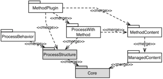
SPEM2.0 comes in form of a MOF-compliant metamodel [7] that reuses UML2.0 Infrastructure [9] and UML2.0 Diagram Interchange specifications [6]. It reuses from the UML Infrastructure basic concepts such as Classifier or Package. No concept from the UML2.0 Superstructure [10] is reused. The Standard comes also in form of UML Profile where each element from the SPEM2.0 metamodel is defined as a stereotype in UML2.0 Superstructure. The meta-model is composed of seven packages linked with the "merge" mechanism (cf [9], §11.9.3), each package dealing with a specific aspect (cf. Fig. 1). The Core package introduces classes and abstractions that build the foundation for all other metamodel packages. The building block of this package is the WorkDefinition class, which generalizes any work within SPEM2.0. The Process Structure package defines elements for representing basic process models in terms of a flow of Activities with their WorkProduct Uses and Roles Uses. However, the possibility to textually document these elements (i.e., add properties describing the element) is not provided in this package but in the Managed Content package, which provides concepts for managing the textual description of process el-ements. Examples of such concepts are the Content Descriptionclass and the Guidance class. The Method Content package defines core concepts for specify-ing basic method contents such as Roles, Tasks and WorkProducts. The Process with Method package de-fines the set of elements required for integrating
pro-Core ProcessStructure ManagedContent MethodContent ProcessWith Method MethodPlugin ProcessBehavior <<merge>> <<merge>> <<merge>> <<merge>> <<merge>> <<merge>> <<merge>> <<merge>> <<merge>>
Figure 1: Structure of SPEM2.0
cesses defined by means of Process Structure package concepts with instances of Method Content package concepts. The Method Plugin package provides mech-anisms for managing and reusing libraries of method contents and processes. This is ensured thanks to the Method Pluginand Method Library concepts. Finally, Process Behavior package provides a way to link SPEM2.0 process elements with external behavior models such as UML2.0 Activity Diagrams or BPMN (Business Process Modeling Notation) models.
3. topProcess: an Overview 3.1 A conception in three steps
Let us borrow some words to the famous singer, author and composer Jacques Brel: “Une valse trois temps, Qui s’offre encore le temps...” that could be translated by “ A waltz in three steps, Which offers even more time...”. This time that we do not dare to spend in the early design phases but whose ultimate aim is to spare, as much as possible, over the whole development! To achieve this aim, it is required to accelerate and rise in power without losing the rhythm, as it is said in the song. The description which follows will be illustrated by a case study of the Aeronautical, Space and Automotive domain that was realized as part of a big project of the pole of competitiveness Aerospace Valley.
3.2 The first step: Referencing
It consists in transforming the paper documents and the knowledge into several structured computer models:
• The repository of the domain. For example CMMI (Capability Maturity Model Integration) [12] which is a standard in software development may be translated in process components. It thus becomes the benchmark model for the concep-tion;
Figure 2: The first step: Referencing
• Repository profession, as TQP (Topcased Qual-ity Process) which is the process of the Topcased toolkit. It respects the Aeronautics (DO178B) [11], Space (ECSS) [3] and Auto-motive (ISO26262) [4] standards. It consists in the global process of integration one the one hand and in the process that all contributors of the Topcased toolkit should respect on the other hand;
• The requirements issued by the various disci-plines which contribute to the global process like quality requirements or management require-ments. These requirements constitutes another repository that the processes will have to respect too;
• The know-how as for example a new technique. It represents the more detailed level of the de-scription.
This referencing and its use as a set of software components is about to considerably modify the abil-ity of designing processes.
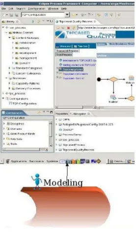
3.3 The second step: Modelling
Modelling consists in using the components already available in libraries. It is then possible to focus on the processes themselves:
• The reference processes: that is those who must be respected by the group or the company. They
Figure 3: The second step: modelling
are at a high level of description and their main purposes is to structure the whole process.
• The processes of domains or specific professions: they include more details related to the corre-sponding domain or some standards.
• The processes will serve as references to the improvement of the projects.
So it is possible to design processes that are built from a common base of standardized process compo-nents without having to deal with any method. 3.4 The third step: Producing
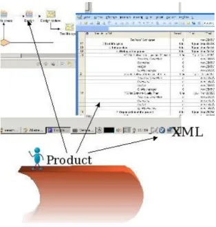
Producing consists in transforming the previous models into tools that assist the development of the systems:
• Tool to assists the teams by providing means to communicate on the process itself :
– Discipline: A collection of related tasks that define a major ’area of concern’. For ex-ample the publication of the quality process that a quality engineer will have to respect whatever is the global process;
– Profession: A collection of related tence that define a major ’area of compe-tence’ for example a Java developer that will
Figure 4: The third step: producing
be told about all his activities and the tools he may use;
– Phases: The time between two major project milestones, during which a well-defined set of objectives is met, and decisions are made to move or not to move into the next phase. Extract the phases to externalize them for example,
– Standards: a publication "adapted" from the standards. Is it very productive to leave 700 pages of the standard ?
– . . .
• By integrating these processes so that they are
"closer" of the concerned people, as for example in Topcased where the process is present at the heart of the development toolkit;
• Finally the production takes all its sense here: the
process becomes a tool to help in the piloting of the projects by supplying the project managers with plans, as MS-Project in the example of figure 4.
It so integrates all the constraints in the processes and offers to your teams the possibility of concentrat-ing on the realization of their product, and nothconcentrat-ing else.
To finish the song ends by a brightness of enjoy-ment: in the third step of the waltz, We waltz finally all three . Of brightness of enjoyment without the continuance and the coordination of set to follow the rhythm imposed by your customers and markets.
4. topProcess applied on the Topcased Quality Process
Topcased Quality Process defines some points in order to build processes for Topcased project under requirements. In this perspective, one can defines some objectives:
• set of processes and tools for the development of software-based systems;
• designed for critical systems (avionics, spatial, automotive)
• respects standards like DO178B, ECSS, IEC 61508 or the future ISO 26262
• Open Source model and high level of quality
• collaboration between industrials, academics and research.
In order to help the project management and to improve the communication with the project stake-holders, this process has been modelled and pub-lished. So, the modelling gives us a better view around the project (components and requirements) and its publication enables better communication with all project members.
The tool used to perform these first experimen-tations on modelling and publishing is EPF, that is presented in the next section.
4.1 Modeling with Eclipse Process Framework Eclipse Process Framework (EPF) is an open source project that is managed by the Eclipse Foun-dation. Launched in 2002, it lies under the top-level Eclipse Technology Project.
EPF Composer provides an environnement for defining any project process parts: First, the “method content” defines roles, the tasks they perform, the work products produced by the tasks. It also defines some templates. It is also possible to define materials to support the project. Then, they can be categorized into logical groups so as to be indexing. As soon as created, the development lifecycle is described. It de-fines a sequence of tasks grouped into activities which can be, in turn, grouped into phases. The development lifecycle contains a selection of phases, activities and tasks. Different types of development lifecycle (incremental, waterfall, iterative) can be modelled.
Then, once all project parts are defined, views can be created. A view contains any project element as needed; like specific elements (roles, tasks, activities, etc), grouped elements (disciplines, domains, life cy-cle, etc), or other views.
After components definition and views structura-tion, it is possible to set the configuration for the pub-lication. Publication exports the project as a website.
This kind of exportation allows any visitor to easily navigate through all the information of the project. Furthermore, because of the publication format, it could be carried out access restriction with sessions mangement for example.
Aside website exportation, EPF Composer provides other kinds of exportation. For example, it is possible to export the whole project for use in other projects; it is also possible to export the process under MS Project format or XML format for project management. It is even possible to export the project as a single XMI file.
So, EPF Composer allows project modelling, project publication and also capitalization.
This way to modelize processes, is applicable for any kind of organization, small and big. Of course for small organizations, it may seem to be a too heavy task, but modelling the process is required to be able to manage processes and to improve communication. Those benefits are seen without doubt as a real help for bigger organizations.
The EPF is applicable to any process, including business processes, technical support processes, as well as systems and software development processes. Then, EPF aims to represent some roles performing tasks and providing documents. However, roles is not only persons; roles can be a system component which performs some tasks and needs information in order to calculate and provide a result.
4.2 Models
EPF Composer, especially designed for this kind of work, respects the UMA metamodel which is more specific than SPEM 2.0.
1) SPEM (Software Process Engineering Meta-model): SPEM is a semi-formal modelling language, that enables the specification of software development process and system, using UML notation.
Conceptually, SPEM describes the software de-velopment process as a relation beetween roles that perform activities, providing work products. It allows the project manager to choose the generic modelling approach that fits with his needs.
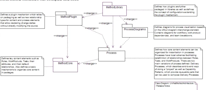
2) UMA (Unified Method Architecture): UMA pro-vides basic access and editing support to the method and process elements stored in a method library. UMA defines the meta-model for how the EPF method content and processes are structured.
The concrete UMA model classes can be grouped into two broad categories (method content and pro-cess) and several sub categories.
a) Method Content: The following UML class diagram shows the organization of the method content classes. They are generated from the uma.ecore file.
UML Class Diagram - UMA Method Content b) Processes: The following UML class dia-gram shows the organization of the process element classes.
UML Class Diagram - UMA Processes
3) Differences beetween UMA and SPEM 2.0: UMA has been designed from SPEM 2.0 to fit with EPF Composer. Therefore, some differences are note-worthy:
• UMA contains less packages than SPEM 2.0
• SPEM 2.0 uses juncture with UML, whereas UMA has been redefined into the meta-model
• because of the UML redefinition, UMA is totally independent (if UML evolve, UMA will not evolve too)
• SPEM 2.0 contains generic guidances, whereas UMA contains specific guidances.
• A set of classes (21) for graphical elements has been defined within UMA (CoreSemantic-ModelBridge, Diagram, DiagramElement, Di-agramLink, Dimension, Ellipse, ..., TextEle-ment, UMASemanticModelBridge)
5. Towards a Formal Process Verification Toolkit In topProcess, we propose a chain of software allowing checking of dynamic properties on the pro-cesses established. Therefore, it is essential to be able to execute the process model.
However, even if process enactment was among the main requirements when the SPEM2.0 RFP was issued [5], the recently adopted specification does not address the enactment issue. Nevertheless, it clearly suggests two possible ways of enacting SPEM2.0 process models: mapping the SPEM2.0 processes models into project plans or linking SPEM2.0 process elements with external behavior formalisms. In these 2 cases, the specification gives no details of imple-mentation for achieving the methods.
To address process model enactment, we propose in [1] an extension of the SPEM2.0 metamodel:
XSPEM. Based on this work, we present in this article some XSPEM tools that we have defined to implement a formal validation of process models.
First, we shortly present the XSPEM metamodel. Then, as a first step, we explain how a graphical
XSPEM process editor has been developed using the GMF framework. This editor allows either to define the whole process model or to extend an existing one (e.g. imported from EPF) to add the project
Figure 5: Main package of the UMA metamodel Activity tmin : EInt tmax: EInt state: ActivityState time: TimeState Parameter direction: DirectionKind charge: EInt WorkBreakdownElement Resource occurencesNb : EInt BreakdownElement name: EString WorkSequence linkKind: WorkSequenceKind <<enumeration>> DirectionKind in out inout <<enumeration>> WorkSequenceKind finishToStart finishToFinish startToStart startToFinish 0..* ownedParameter 1 parameterType 0..* nestedBreakdownElement predecessor 1 0..* linkToSuccessor successor 1 0..* linkToPredecessor <<enumeration>> ActivityState notStarted started finished <<enumeration>> TimeState ok tooLate tooEarly
Figure 6:XSPEM metamodel (simplified)
characteristics such as activity durations, resource allocation...
As a second step, we present the translation from a
XSPEM model to PRIORITIZED TIMEPETRI NETS
model. The purpose of the translation is to be able to use model-checker (e.g. Tina) defined for Petri nets to validate the original process model.
5.1 Description of the Simplified XSPEM
In our experiments, we used a simple process de-scription language, the simplified XSPEM metamodel (fig. 6).
XSPEM, for eXecutable SPEM, is proposed in [1] as an extention of SPEM2.0 specification [8] in order to take into account the support of process enactments
while remaining standard. In the metamodel, an Ac-tivity is a concrete WorkDefinition that represents a general unit of work assignable to specific performers and which can rely on inputs and produces outputs (represented by Resource). An activity may be broken down into sub-activities. Activities are ordered thanks to the WorkSequence concept whose attribute linkKind indicates when an activity can be started or finished. The direction attributes defined in Parameter could be used to complete sequencing constraints expressed through the WorkSequence concept.
In order to tailor a process model for a given project, additional features have to be defined. It is required to dimension activities, i.e., specify the number of used resources, expected duration, etc., and to identify the concrete resources allocated to the project.
XSPEM include: 1) the time interval during which an activity must finish (tmin and tmax on Activity); 2) the number of occurrences for one Resources affected to the project (occurrencesNb on Resource); 3) the work load affected to a resource for an activity (charge on Parameter).
In order to enact a process model, its semantics has to be defined and the first step consists in adding features to the metamodel to capture states. XSPEM identify two orthogonal aspects for the Activity ele-ment. First, an activity can be not started, started, and finally finished (state attribute). Secondly, there is a notion of time and clock associated to each activity; but this time is only relevant for transition-enabling
conditions (in our case transitions that start and finish an activity) and is not explicit in state properties. Thus it can be represented into the finite set of states {tooEarly, ok , tooLate} (time attribute). This second orthogonal aspect is only relevant when the activity is finished. It is also necessary to take into account the concept of a clock (clock ∈ R+), internal to an activity. It is not represented in the metamodel because only the abstraction is necessary, the clock being taken into account by the execution engine. 5.2 TopProcess Modeler: the Topcased xSPEM mod-eler
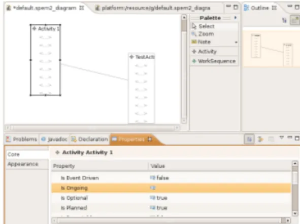
1) TopProcess Modeler Description: TopProcess modeler provides a new way of modelling software development processes. We indeed think that the current way of modelling processes with EPF is not really straight forward for non experimented users. It is mainly due to the table orientation of EPF. Indeed, EPF users have first to fill in many huge tables with all the information on the process. It is only after that EPF may be used to automatically generate nice graphical diagrams through the publication features. In the TopProcess Modeler, we aim to reverse this way of thinking. Users start by creating diagrams using drag&drop tools. This allow them to clearly see whether their processes are good without having to generate any publication. Furthermore, they can concentrate on the overall structure of the process be-fore to enter all the information about the elements of this process. As the matter of fact, process designers will act the same way as Java developers do. They indeed design the architecture of their applications thanks to UML class diagrams before to writing code corresponding to the details of the classes.
In the first iteration of the TopProcess Modeler, two diagrams have been implemented:
• the Activity Diagram (fig. 8): One user can describe the activities of its process and their dependencies (usign WorkSequences). The activ-ity diagram is hierarchical in the sense that the user may attached a sub-activity diagram to one activity to detail it.
• the tasks diagram (fig. 9): the user describes all the tasks related to an activity, including the products, their statements before and after a task and the tools used for this task. In a near future, roles will be added to this diagram.
2) Developing with the Graphical Modeling Framework: GMF (Graphical Modeling Framework)5
5
http://www.eclipse.org/gmf/
Figure 8: A screenshot of the TopProcess modeler: The Activity Diagram
Figure 9: A screenshot of the topProcess modeler: the Task Diagram
is an Eclipse plugin which allows to develop fully functional graphical diagram editors. GMF is based two other plugins: GEF (Graphical Editing Frame-work) and EMF (Eclipse Modeling FrameFrame-work). Join-ing these two plugins makes the development of graphical editors far much easier for developers be-cause they does not have to worry about how to link EMF and GEF projects. Most of the graphical editors is generated from the description that should provide the developpers.
Creating a new diagram editor with GMF may be fairly simple. The development is divided in five main following steps.
• The first step consists in creating the Ecore model of the domain metamodel. In our case, the metamodel is mainly based on SPEM with some information added to handle the enactment of processes. GMF only deals with Ecore files. Anyway, it is possible to import models from other tools such as Rose but in all case, GMF will convert it in an Ecore model.
• The second step is about defining the graphical elements. From the Ecore model, one has to select the root class for the diagram. After that, GMF will pre-select all elements related to this root class. It is up to the developer to check this
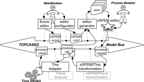
Process Modeler MetaModeler xSPEM editor xSPEM2Fiacre transformation Fiacre Analyser
TOPCASED Model Bus
Ecore editor editor generator xSPEM2Tina transformation Tina Adapter xSPEM .ecore editor configurator xSPEM .conf .java process .xspem process .ltl process .net process .result Tina toolkit
Figure 7: TOPCASED integration of the xSPEM models validation
pre selection and to modify it if needed. You can also choose how elements will be displayed (either as node or as links between two nodes).
• The third step deals with the palette generation. As in the second step, one has to select the root class and then GMF pre-selects related elements. If no modifications are done in the pre-selection in the previous step, no modifications will be needed here.
• The fourth step aims to link the metamodel de-scription, the graphical elements and the palette. It consists in defining all the interactions between graphical elements and the properties the user could modify (or not).
• The final step is the code generation of the graphical editor.
TopProcess Modeler is fully developed with a Model Driven Engineering approach. The main ad-vantage is that we have focused on the metamodel, its concepts and the way to handle them in the editor instead of dealing with pure coding issues. Using GMF allows us to generate nice editors without writing any line of code, which is really enjoyable. Of course, if we want to customize the generated editor or add some functionality such as printing or import/export capabilities some line of Java code will have de be written because these aspects are not yet handled by the GMF framework. The only drawback of this approach is that it is really difficult to understand the generated code when we have to tweak it (but once the generated code is understood, it is nearly the same as for all developed editors).
5.3 xSPEM2Tina: a Topcased Service to SPEM pro-cess verification
In this section, we propose to implement semantics informaly defined in the SPEM2.0 specification [8] and formaly defined in [1]. We formalized a transfor-mation from XSPEM to PRIORITIZED TIME PETRI
NETS (PrTPN) to define a translational semantics for XSPEM. This transformation has been written in ATL whose complete sources are available in the TOPCASED project. Principles of this approach are detailled through a complete case study on the Eclipse website within the context of an execution dedicated
XSPEM subset (SIMPLEPDL)6.
As a first step, the XSPEM model is translated to a
Petri net model conforms to the PRIORITIZEDTIME
PETRINETS metamodel. The Petri net model is then
translated into the concrete syntax of Tina using an ATL query PETRINET2TINA. To reuse other Petri
nets tools, only this last transformation would have do be adapted.
Now that the process model is translated into a Petri net model, we can checkXSPEM properties by using TINA7. Properties expressed on the XSPEM meta-model leads to an ATL transformation that produces the corresponding LTL properties instantiated from the XSPEM model [2].
There are two kinds of checked properties: existen-tial or universal. In the first case, the property must be checked in all execution. If it is not the case, the tool provides a trace counter-example property. The second case corresponds to checking that one possible
6
http://eclipse.org/m2m/atl/usecases/SimplePDL2Tina
7
execution satisfies the property, for example the time or resources constraints. If one execution exists, the trace is generated by the tool.
All this chain of validation is currently under implementation in Topcased in the form of two ser-vices available on the model bus (fig. 7). The first (xSPEM2Tina transformation) takes as inputXSPEM model thanks to the XSPEM editor. It calls the two ATL transformations to provide files of Petri nets and LTL properties. The second service (Tina Adapter) performs the verification of properties on Petri nets through the TINA toolbox. It then provides a file of results including counter-examples for properties which are false.
6. Conclusion & Perspectives
This article presents the TOPCASED integration of the TopProcess approach. As a first step, we present a general framework and the modeling of the project requirements through EPF. Then we detail XSPEM, an extension of SPEM 2.0, which supports models execution and tools for edition and validation.
After the current user-friendly integration in TOP-CASED (fig. 7), many perspectives can be developed on the basis of this work. The first of these is the study to generalize the feedback of an analysis realized by using a translation semantics. For the moment, we use the naming convention defined in the translation semantics. Then, we wish to explore the definition of the FIACRE intermediate language available soon in TOPCASED. We will change the translation of the
XSPEM semantics to translate into FIACRE and then reuse the available FIACRE services (fig. 7, in grey).
References
[1] R. Bendraou, B. Combemale, X. Crgut, and M.-P. Gervais. Definition of an eXecutable SPEM2.0. In 14th Asian-Pacific Software Engineering Conference (APSEC), pages 390–397, Nagoya, Japan, Dec. 2007. IEEE Computer Society. [2] B. Combemale, P.-L. Garoche, X. Crgut, and X. Thirioux.
Towards a Formal Verification of Process Model’s Properties – SimplePDL and TOCL case study. In 9th International Conference on Enterprise Information Systems (ICEIS), pages 80–89, Portugal, June 2007. INSTICC.
[3] European Cooperation for Space Standardization. Standards for use in all European space activities, Mar. 2005. [4] International Organization for Standardization.
Func-tional safety of electrical/electronic/programmable elec-tronic safety-related systems for Automotive, Mar. 2008. [5] Object Management Group, Inc. Software Process
Engi-neering Metamodel (SPEM) 2.0 RFP, Nov. 2004.
[6] Object Management Group, Inc. Diagram Interchange 1.0 Specification, Apr. 2006.
[7] Object Management Group, Inc. Meta Object Facility (MOF) 2.0 Core, Jan. 2006.
[8] Object Management Group, Inc. Software Process Engi-neering Metamodel (SPEM) 2.0, Mar. 2007.
[9] Object Management Group, Inc. Unified Modeling Lan-guage (UML) 2.1.1 Infrastructure, Feb. 2007.
[10] Object Management Group, Inc. Unified Modeling Lan-guage (UML) 2.1.1 Superstructure, Feb. 2007.
[11] RTCA. Software Considerations in Airborne Systems and Equipment Certification, Dec. 1992.
[12] Software Engineering Institute. Capability Maturity Model Integrationl (CMMI) 1.2, Aug. 2006.