Publisher’s version / Version de l'éditeur:
Optics Express, 18, 4, pp. 3784-3792, 2010-02-05
READ THESE TERMS AND CONDITIONS CAREFULLY BEFORE USING THIS WEBSITE.
https://nrc-publications.canada.ca/eng/copyright
Vous avez des questions? Nous pouvons vous aider. Pour communiquer directement avec un auteur, consultez la première page de la revue dans laquelle son article a été publié afin de trouver ses coordonnées. Si vous n’arrivez pas à les repérer, communiquez avec nous à [email protected].
Questions? Contact the NRC Publications Archive team at
[email protected]. If you wish to email the authors directly, please see the first page of the publication for their contact information.
NRC Publications Archive
Archives des publications du CNRC
This publication could be one of several versions: author’s original, accepted manuscript or the publisher’s version. / La version de cette publication peut être l’une des suivantes : la version prépublication de l’auteur, la version acceptée du manuscrit ou la version de l’éditeur.
For the publisher’s version, please access the DOI link below./ Pour consulter la version de l’éditeur, utilisez le lien DOI ci-dessous.
https://doi.org/10.1364/OE.18.003784
Access and use of this website and the material on it are subject to the Terms and Conditions set forth at
Optical coatings with an integral FTIR air layer
Li, Li; Dobrowolski, J. A.
https://publications-cnrc.canada.ca/fra/droits
L’accès à ce site Web et l’utilisation de son contenu sont assujettis aux conditions présentées dans le site LISEZ CES CONDITIONS ATTENTIVEMENT AVANT D’UTILISER CE SITE WEB.
NRC Publications Record / Notice d'Archives des publications de CNRC:
https://nrc-publications.canada.ca/eng/view/object/?id=0155004a-1ca2-457d-a3c9-ed428087594b https://publications-cnrc.canada.ca/fra/voir/objet/?id=0155004a-1ca2-457d-a3c9-ed428087594bOptical coatings with an integral FTIR air layer
Li Li* and J. A. DobrowolskiInstitute for Microstructural Sciences, National Research Council of Canada 1200 Montreal Road, Ottawa, Ontario, K1A 0R6, Canada
Abstract: The use of solid frustrated total internal reflection (FTIR) layers to control the polarization effects in optical coatings usually results in large substrate sizes and complicated designs. To overcome this problem, it is proposed to incorporate an air FTIR layer into the multilayer thin film coatings. The low refractive index of air not only helps to reduce the substrate sizes, but also simplifies coating designs or improves the performance. The principle and layer structures of the proposed multilayers are described. Examples of polarizing- and non-polarizing beam-splitters for the infrared spectral region are given. Some practical manufacturing issues are also discussed.
©2010 Optical Society of America
OCIS codes: (310.0310) Thin films; (310.1620) Interference coatings; (310.5448) Polarization, other optical properties.
References and Links
1. H. A. Macleod, Thin Film Optical Filters, 3rd edition, (Institute of Physics, Bristol, 2001).
2. L. Li, and J. A. Dobrowolski, “High-performance thin-film polarizing beam splitter operating at angles greater than the critical angle,” Appl. Opt. 39(16), 2754–2771 (2000).
3. L. Li, “The design of optical thin film coatings with total and frustrated total internal reflection,” Opt. Photonics News 14(9), 24–30 (2003).
4. M. Zukic, and K. H. Guenther, “Design of nonpolarizing achromatic beamsplitters with dielectric multilayers,” Opt. Eng. 28, 165–171 (1989).
5. H. A. Macleod and Z. Milanovic, “Immersed beamsplitter-an old problem,” Optical Interference Coatings (OIC), 28–30 (1992).
6. L. Li, P. Ma and P. Verly, “Non-polarizing thin film interference filters with FTIR,” Optical Interference Coatings (OIC), ThD3 (2004).
7. J. A. Dobrowolski, “Optical properties of films and coatings,” Handbook of Optics, 2nd edition, M. Bass, ed., Optical Society of America, (McGraw-Hill, New York, 42.1–42.130, 1995).
8. L. Li, D. Poitras and X. Tong, “Broadband tunable Fabry-Perot filters,” Optical Interference Coatings (OIC), ThB3 (2004).
9. E. E. Hall, “The penetration of totally reflected light into rarer medium,” Phys. Rev. 15, 73–106 (1902). 10. L. Li, and J. A. Dobrowolski, “Visible broadband, wide-angle, thin-film multilayer polarizing beam splitter,”
Appl. Opt. 35(13), 2221–2225 (1996).
11. E. D. Palik, Handbook of Optical Constants of Solids I Academic Press Inc., Orlando, (1985)
12. J. A. Dobrowolski, “Coatings and Filters,” in Handbook of Optics W.G. Driscoll and W. Vaughan, eds., (McGraw-Hill, New York, 8.1–8.124, 1978).
1. Introduction
Thin film optical coatings or filters are often used in applications that require light incident at non-normal or oblique angles of incidence in order to physically separate the incident, reflected and transmitted beams from each other. In optical imaging systems, coatings on prism substrates are often preferred over coatings on titled plates because the latter give rise to large off-angle aberrations, such as astigmatism, that are difficult to correct.
One issue with optical coatings used at oblique angles, especially on prism substrates, is the polarization effect between s- and p-polarized light. This often results in different coating properties (for example, reflectance, transmittance, or phase changes on reflection or transmission) for the s- and p- polarizations. It is caused by the different optical admittances of s- and p-polarized light at oblique angles [1]. For polarizing beam-splitters, this
polarization effect is desirable and needs to be enhanced as much as possible in order to reflect light in s- or p-polarization and transmit light in the other polarization. For many other optical coatings, such as non-polarizing beam-splitters, cut-off filters and bandpass filters, the polarization effect is undesirable and must be minimized.
Using thin film interference alone to enhance or minimize the polarization effects often does not produce entirely satisfactory results. However, it has been demonstrated that the combination of frustrated total internal reflection (FTIR) and thin film interference is very effective in the design of polarizing and non-polarizing thin film beam-splitters operating at angles greater than the critical angle [2–6]. These coatings consist of solid thin film layers sandwiched between two high refractive index prisms. Frustrated total internal reflection occurs in some of the low refractive index layers within the multilayers.
There are several problems with solid FTIR layers. For example, in the infrared spectral region ZnS and ZnSe are commonly used as the low index layer material and the substrate material. This combination results in a very large critical angle above which the optical coatings must operate. This, in turn, necessitates the use of undesirably large prisms. Similar issues also exist in the visible spectrum. Another problem is that high refractive index prism substrates must be used and that the bonding of the coated prisms can be challenging. In the visible region no suitable high transparency optical cements are available with refractive indices n0>1.65; in the infrared region (3-15 m) no transparent glues exist at all. Thus, the
more expensive optical contacting must be used to bond the coated substrates. This process is more difficult when a large coated area is required to be contacted.
In this paper, we propose a different way to design FTIR optical thin film coatings by introducing an air layer as an integral part of the multilayer interference coating. Air layers have been used in interference coatings before, for example in resonant reflectors [7] or in tunable narrow band filters [8]. However, both these devices operate at normal incidence. In our proposed coatings, the air layer works above the critical angle and since its thickness is relatively thin compared to the wavelength of the light, FTIR occurs inside the layer. The use of an air layer can significantly reduce the critical angle because air has a low refractive index of 1. As a result, the angles of incidence within the coating are significantly reduced and so are the size of the prism substrates and the manufacturing costs. In addition, the air layer is bounded by a spacer layer that has a much smaller area for the optical contacting. Furthermore, it will be shown below that the use of an air layer in the system also helps to improve its performance and results in coating designs with fewer layers and/or smaller total thicknesses.
In Section 2, the design principle as well as the typical layer structure of the FTIR multilayer coating with an integral air layer is described. Two different design examples, a polarizing beam-splitter (PBS) and a non-polarizing beam-splitter (NPBS), are given in Section 3. Some practical manufacturing issues - the effect of thickness and index errors and substrate flatness - are discussed in Section 4. Finally, some conclusions are drawn in Section 5.
2. Principle of optical thin film coatings with an integrated air layer
The reason why FTIR can be used so effectively to control polarization effects in thin film coatings is mainly due to two unique phenomena that only occur when the incident angles are greater than the critical angle. One is that the phase changes on reflection and transmission are different for s- and p-polarized light above the critical angle. The second effect is the difference in behavior of high and low refractive index layers above the critical angles. The following section will explain these two phenomena and also the impact of an air FTIR layer. 2.1 Phase changes on reflection at an interface with two media n0 and n1
When light is incident from a medium or layer with a refractive index n0 to another medium
as the refractive index ratio n0/n1, as shown in Fig. 1 [2,3]. In an FTIR optical thin film
coating where the incident angles are greater than the critical angle (n0/n1>1 and θ0>θC) within low index FTIR layers, the phase changes on reflection at high/low layer interfaces are not fixed at 0° or 180° anymore but vary with angle of incidence and the polarization state. Thus, these phase changes on reflection were additional variables that could be used in the design of high-performance polarizing beam-splitters operating above the critical angle and which reflect p-polarized light and transmit s-polarized light [2].
For infrared coatings with ZnSe substrate n0 = 2.4 and ZnS low index layers n1 = 2.2, the
index ratio n0/n1 and the critical angle θC are 1.091 and 66.44°. The large θC is too high for many coating applications. However, if the low index layer is replaced by an air layer with n1
= 1.0, the critical angle is reduced significantly from 66.44° to 24.62°.
Fig. 1. Variation of the phase change on reflection with angle of incidence θ0 and refractive
index ratio n0/n1: a. s-polarization, b. p-polarization (reproduced from reference [3])
2.2 Property of low index FTIR layers
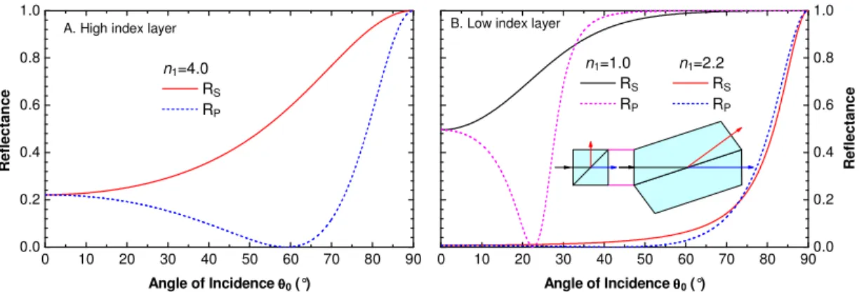
The different behavior of high and low index layers above the critical angles can be demonstrated with the calculated reflectance of single layers as shown in Fig. 2.
For the high index layer n1 = 4.0 in Fig. 2a, the reflectance of s-polarized light is always
higher than that of the p-polarized light, regardless of the angle of incidence. However, for the low index layers in Fig. 2b, there exists an incident angle θN at which the reflectance of s- and p-polarized light is the same and thus there is no polarization effect at that angle. This non-polarizing angle θN, first discovered by Hall in 1902 [9], is independent of the wavelength and layer thickness. Below the angle θN the reflectance of s-polarized light is always greater than that for p-polarized light; at the Brewster angle θB the reflectance for p-polarized light is zero. But above the angle θN, the reflectance of s-polarized light is lower than that of p-polarized light. This phenomenon explains why a conventional polarizing beam-splitter working at incident angles below the critical angle always reflects s-polarized light and transmits p-polarized light [10], and why a polarizing beam-splitter designed for operation above the critical angle transmits s-polarized light and reflects p-polarized light [2].
Since a multilayer coating often consists of low and high index layers, these opposite behaviors of low and high index layers can be used to compensate each other and thus be used to minimize polarization effects in non-polarizing beam-splitters [3–5]. This idea has also been extended for the design of other types of non-polarizing filters [6]. The design angles for these coatings do not have to be at the non-polarizing angle, it can be higher than the non-polarizing angle because the non-polarizing effect can be compensated by adjusting the layer thicknesses of the low and high index films.
0 10 20 30 40 50 60 70 80 900.0 0.2 0.4 0.6 0.8 1.0 R e fl e c ta n c e Angle of Incidence θθθθ0 (°) n1=1.0 n1=2.2 RS RS RP RP
B. Low index layer
0 10 20 30 40 50 60 70 80 90 0.0 0.2 0.4 0.6 0.8 1.0 Angle of Incidence θθθθ0 (°) n1=4.0 RS RP R e fl e c ta n c e
A. High index layer
Fig. 2. Reflectance of a single layer n0 / n1 / n0 at 10 m, substrate ZnSe n0 = 2.40.
A. a high index layer Ge n1 = 4.0; B: low index layers air n1 = 1.0 and ZnS n1 = 2.2
The definitions of the Brewster angle θB, critical angle θC and non-polarizing angle θN are:
1 0 1 0 2 2 2 1 1 0 arctan( / ) arcsin( / ) , and arcsin( 2 / ( )) B C B C N N n n n n n n n θ θ θ θ θ θ = = < < = + . (1)
For a single layer with a low index n1 = 2.20, the non-polarizing angle is calculated to be
72.87°. If a non-polarizing beam-splitter were to be made with multiple layers of ZnS and Ge on a ZnSe substrate at 72.87°, the prism size would be huge, as seen in the insert in Fig. 2b.
To lower the incident angle, we have to use low refractive index FTIR layers. Some oxide and fluoride materials do have lower refractive indices than ZnS and are sometimes used in parts of the infrared region from 3 – 15 m. But many of these materials, especially for oxide films, have strong absorptions at longer wavelengths and so they cannot be used there. In addition, some of these materials have Reststrahlen bands in the infrared region in which their optical constants change rapidly with wavelength [11,12]. This is very undesirable for the design of filters for broad band spectral regions. Furthermore, fluoride materials are often very soft and can have a low packing density, which leads to a filter performance change with humidity and temperatures – another effect that is not desirable.
This led us to look for a non-absorbing material with a lower refractive index and small dispersion. The most convenient material that meets these requirements is air.
Clearly, in Fig. 2b, when the ZnS layer with n1 = 2.2 is replaced by the air layer n1 = 1.0,
the non-polarizing angle is reduced from 72.87° to 32.95°. If a non-polarizing beam-splitter were made for the somewhat higher, but more convenient, angle of incidence of 45°, using multiple ZnS and Ge layers and just a single air FTIR layer, a significant reduction in the size of the prism could be achieved. The insert diagram in Fig. 2b compares the prism sizes for the same beam size using ZnS and air FTIR layers. Other types of FTIR coatings can also benefit from the use of a single air FTIR layer.
Because of the higher refractive index ratio of nH/nL, the use of an air FTIR layer can also
improve the coating performance and/or simplify coating designs – these points will be demonstrated in Section 3.
2.3 Layer structure of optical thin film coatings with an integral FTIR air layer
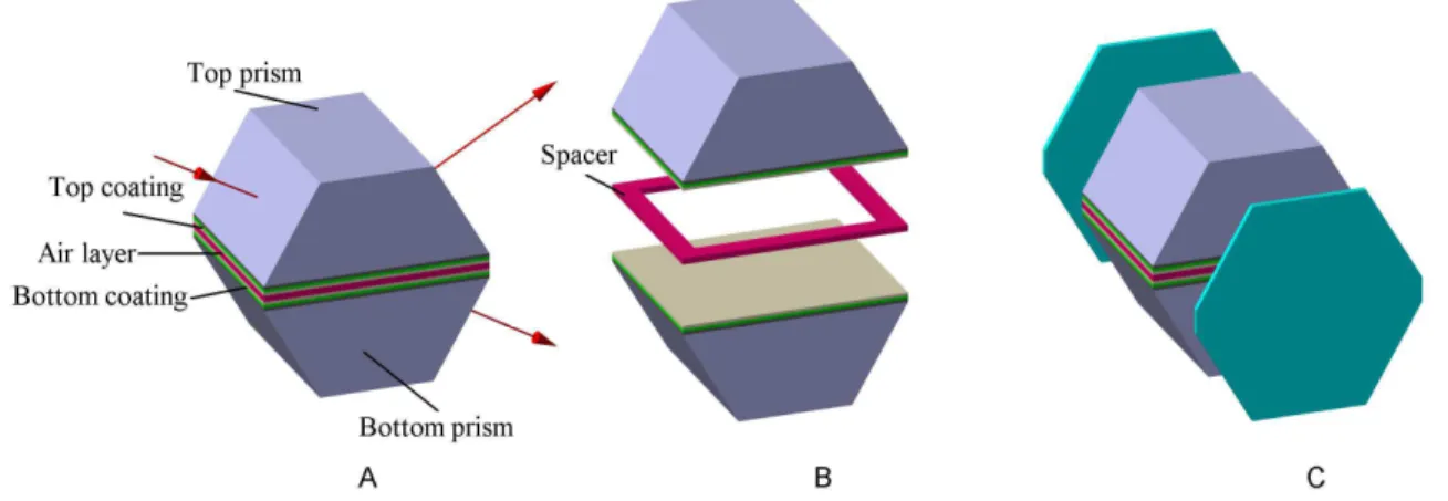
The layer structure of the proposed optical thin film coatings with an integral FTIR air layer is shown in Fig. 3. The optical coating is sandwiched between two high index prism substrates.
It consists of multilayer thin films, including top and bottom coatings made of solid layers and an air layer that separates the two. The thickness of the air layer is defined by the thickness of a spacer layer that can be deposited through a shadow mask, as shown in Fig. 3b. The two prisms are optically contacted only at the spacer layer, thus minimizing the area required for the contacting. Two additional plates made of the same glass material can be glued to the sides of the prisms as shown in Fig. 3c to strengthen the resulting optical component.
Fig. 3. Optical thin film coatings with an integral air layer: A – a typical structure, B – an exploded view of the structure, C – a structure with side panels.
Various shapes of spacer layers can be used. For example, the spacer layers can be two parallel bars along the length or the width of the coated area. The spacer layer can be made out of a different coating material that is better suited for optical contacting.
3. Examples of optical thin film coatings with an integral air layer
In principle the above proposed thin film coatings with an integral air FTIR layer can be used in the short wavelength regions such as the visible and near infrared. However, because of some practical manufacturing issues with surface flatness (to be discussed in Section 4), they are more suitable for the infrared spectral region. For this reason, the following two examples are given for the infrared spectral region from 650 cm−1 to 1700 cm−1 (5.88 m to 15.38 m). For this region, we select ZnS and Ge as the low and high index materials and ZnSe as the substrate material without much absorption. The optical constants of ZnS, Ge and ZnSe were taken from the reference [11].
800 1000 1200 1400 1600 10 -4 10-3 10-2 10-1 100 Wavenumber (CM-1) RP (angles in glass/Air) 68° / - 9.6° 70° /- 4.8° 72° / 0.0° 74° / 4.8° 76° / 9.6° B3 RS (angles in glass/Air) 68° / - 9.6° 70° /- 4.8° 72° / 0.0° 74° / 4.8° 76° / 9.6° RS 800 1000 1200 1400 1600 0.980 0.985 0.990 0.995 1.000 Wavenumber (CM-1) RP (angles in glass/Air) 72° /- 9.6° 74° /- 4.8° 76° / 0.0° 78° / 4.8° 80° / 9.6° RP A3 RS (angles in glass/Air) 72° /- 9.6° 74° /- 4.8° 76° / 0.0° 78° / 4.8° 80° / 9.6° 0 5 10 15 20 25 30 35 0 1 2 3 4 5
Incident angle (glass/air): 72°±4° / ±9.6°
N=15, Σdi=9.183 m, MF=0.0897
Sub.
Thickness ( m)
B1
Inc.
B: PBS2 with Air FTIR Layer
R e fr a c ti v e I n d e x 0 5 10 15 20 25 30 35 0 1 2 3 4 5
A: PBS1 with Solid FTIR Layers
Incident angle (glass/air): 76°±4° / ±9.6°
N=43, Σdi=33.291 m, MF=0.0921 Sub. Thickness ( m) R e fr a c ti v e I n d e x A1 Inc. 0.980 0.985 0.990 0.995 1.000 14 12 10 8 6 TS (angles in glass/Air) 72° /- 9.6° 74° /- 4.8° 76° / 0.0° 78° / 4.8° 80° / 9.6° TS A2 TP (angles in glass/Air) 72° /- 9.6° 74° /- 4.8° 76° / 0.0° 78° / 4.8° 80° / 9.6° Wavelength ( m) 10-4 10-3 10-2 10-1 100 14 12 10 8 6 TS (angles in glass/Air) 68° / - 9.6° 70° /- 4.8° 72° / 0.0° 74° / 4.8° 76° / 9.6° B2 TP (angles in glass/Air) 68° / - 9.6° 70° /- 4.8° 72° / 0.0° 74° / 4.8° 76° / 9.6° T P Wavelength ( m)
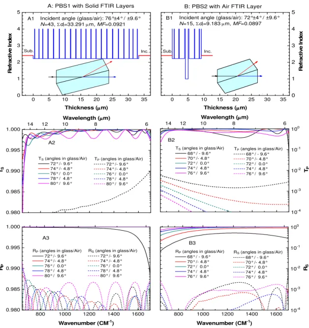
Fig. 4. Polarizing beam-splitters: column A, PBS1 with solid FTIR layers; column B, PBS2 with air FTIR layer; row 1: refractive index profiles of systems PBS1 and PBS2; row 2: calculated transmittances Ts and Tp; row 3 calculated reflectances Rs and Rp. N, Σdi and MF are the number of layers, total thicknesses and merit function values of the layer systems, respectively.
Examples are only given for polarizing- (Fig. 4) and non-polarizing (Fig. 5) beam-splitters, although the principle has been successfully applied to other types of non-polarizing devices, such as cut-off- and bandpass filters. To show the effectiveness of the integral air layer, we first present in column A of each figure the results for coating designs based on solid FTIR layers (PBS1, NPBS1), and then, in column B, the results for coating designs with an integral FTIR air layer (PBS2, NPBS2).
The design specifications for the polarizing beam-splitter designs were the following. The required angular field was specified to be ± 9.6° in air or ± 4.0° in the ZnSe substrate. The
performance targets were set to be Rs = 0.0 and Tp = 0.0 from 650 cm−1 to 1700 cm−1 with 5 cm−1 steps in wavenumber and with 0.5° steps in the angle of incidence measured in the substrate. 0 5 10 0 1 2 3 4 5
A: NPBS1 with Solid FTIR Layers
Incident angle (glass/air): 72.0°±1.5° / ±3.6°
N=19, Σdi=10.905 m, MF=3.480 Sub. Thickness ( m) R e fr a c ti v e I n d e x A1 Inc. 800 1000 1200 1400 1600 0.0 0.2 0.4 0.6 0.8 1.0 TP B3 Wavenumber (CM-1) Angles in glass/Air 43.5° (- 3.6°) 44.5° (- 1.8°) 45.5° ( 1.8°) 46.5° ( 3.6°) 800 1000 1200 1400 1600 0.0 0.2 0.4 0.6 0.8 1.0 Wavenumber (CM-1) Angles in glass/Air 70.5° / - 3.6° 71.5° / - 1.8° 72.5° / 1.8° 73.5° / 3.6° TP A3 0.0 0.2 0.4 0.6 0.8 1.0 14 12 10 8 6 TS B2 Angles in glass/Air 43.5° (- 3.6°) 44.5° (- 1.8°) 45.5° ( 1.8°) 46.5° ( 3.6°) Wavelength ( m) 0.0 0.2 0.4 0.6 0.8 1.0 14 12 10 8 6 TS Angles in glass/Air 70.5° / - 3.6° 71.5° / - 1.8° 72.5° / 1.8° 73.5° / 3.6° A2 Wavelength ( m) 0 5 10 0 1 2 3 4 5 R e fr a c ti v e I n d e x Sub. Thickness ( m) Inc.
B: NPBS2 with Air FTIR Layer
Incident angle (glass/air): 45.0°±1.5° / ±3.6°
N=11, Σdi=4.976 m, MF=2.050 B1
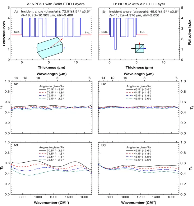
Fig. 5. Non-polarizing beam-splitters, column A: NPBS1 with solid FTIR layers; column B: NPBS2 with air FTIR layer; row 1: layer systems; rows 2 and 3: calculated transmittances Ts and Tp
Row 1 in Fig. 4 presents the refractive index profiles of the solutions, and lists the number of layers N, the total metric thickness Σdi and the merit function values MF of the two solutions obtained. The transmittances Ts (linear, left axis) and Tp (logarithmic, right axis) for the coatings at the various angles of interest are shown in row 2. Similarly, the reflectances Rp (linear, left axis) and Rs (logarithmic, right axis) are shown in row 3. The coating designs PBS1 and PBS2 have similar merit functions values of 0.0921 and 0.0897 and their overall
performance is comparable (most of the transmittances for p-polarized light are below 10−4 and thus are not shown in the diagram). However, PBS2’s coating design with the air FTIR layer is much simpler and is thus much easier to deposit. It has only 15 layers, a total thickness of 9.183 m and an angular field from 68° - 76°. In comparison, PBS1 has 43 layers, a 33.291 m total thickness, and larger angles of incidence from 72° - 80°. The use of an air FTIR layer reduces the incident angles by 4° in PBS2 and results in a smaller prism size compared to PBS1 shown as the inserts of Fig. 4 row 1.
The following were the design specifications for the non-polarizing beam-splitter designs. The required angular field was specified to be ± 3.6° in air or ± 1.5° in the ZnSe substrate. The performance targets were set to be Ts = Rs = 0.5 and Tp = Rp = 0.5 all with a tolerance of ± 0.01, from 650 cm−1 to 1700 cm−1 with 5 cm−1 steps in wavenumber and with 0.2° steps in the angle of incidence measured in the substrate.
Row 1 in Fig. 5 presents the refractive index profiles and lists N, Σdi and MF values for the two solutions. The linear transmittances Ts and Tp for the two systems at the various angles of interest are shown in rows 2 and 3. The coating design NPBS2 has a smaller merit function 2.050 and thus has a better performance than design NPBS1 (merit function 3.480) as shown in Fig. 5. Similarly, the coating design NPBS2 with an air FTIR layer is much simpler than NPBS1. It has only 11 layers compared to 19 layers in PBS1, and a total layer thickness of 4.976 m, compared to NPBS1 10.905 m. The 27° reduction in incident angles from 70.5° to 73.5° in NPBS1 without an air layer to 43.5° to 46.5°, is significant for reducing the prism size as shown in the insert diagrams of Fig. 5 A1 and B1. It would be much easier to produce the NPBS2 device.
4. Practical considerations
To fabricate the above coatings with air FTIR layers, we must consider some practical issues. First is the sensitivity of the coating performance to thickness and index errors. Second is the flatness of the substrate. The non-flatness of the substrate translates into a non-uniformity of the integral air layer.
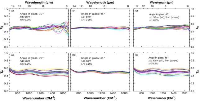
800 1000 1200 1400 1600 0.0 0.2 0.4 0.6 0.8 1.0 TP Wavenumber (CM-1) Angle in glass: 45° d: 30nm (air), 5nm (others) n: 0.2% C2 0.0 0.2 0.4 0.6 0.8 1.0 14 12 10 8 6 TS Angle in glass: 45° d: 30nm (air), 5nm (others) n: 0.2% C1 Wavelength ( m) 800 1000 1200 1400 1600 Wavenumber (CM-1) Angle in glass: 45° d: 5nm n: 0.2% B2 14 12 10 8 6 Angle in glass: 45° d: 5nm n: 0.2% B1 Wavelength ( m) 800 1000 1200 1400 1600 0.0 0.2 0.4 0.6 0.8 1.0 Wavenumber (CM-1) Angle in glass: 72° d: 5nm n: 0.2% TP A2 0.0 0.2 0.4 0.6 0.8 1.0 14 12 10 8 6 Angle in glass: 72° d: 5nm n: 0.2% TS A1 Wavelength ( m)
Fig. 6. Effect of random thickness and refractive index errors on non-polarizing beam-splitters. Column A: NPBS1 with solid FTIR layers; column B: NPBS2 with an air FTIR layer; column C: NPBS2 with same errors as in column B except for the air layer; Rows 1, 2: calculated transmittances Ts and Tp
We use the non-polarizing beam-splitter designs NPBS1 and NPBS2 to illustrate these issues. We assume that every layer has random thickness and refractive index errors. In our calculations the standard deviations of these errors were 5 nm and 0.2% (for ZnS, Ge and air), respectively. Figure 6 shows the calculated transmittances Ts and Tp at the central design angles 72° and 45° of 20 randomly perturbed systems NPBS1 (column A) and NPBS2 (column B). Results were slightly better for NPBS2 if we considered that the air refractive index was not perturbed. We found that, in general, the performance of FTIR coatings is more sensitive to the FTIR layer thickness or index errors. Since in the design NPBS2 there is only one FTIR layer – air, the design appears to be less sensitive to layer thickness and index errors than the NPBS1 system which has 7 ZnS FTIR layers. However, in the case of NPBS2 system, the thickness of the air layer is governed by the flatness of the substrates. If the flatness of the prism surfaces is λ/40 (λ = 633nm), this will translate to a maximum thickness error about 30nm in the air layer. Figure 6 column C shows the calculated transmittances Ts and Tp of NPBS2 at 45° with the same thickness and index errors except for the air layer which has a standard thickness error deviation of 30nm. With this error margin on the air layer, the performance is still comparable to that of the all solid layer design NPBS1. To minimize the thickness error in the air layer, two matching prism substrates with similar surface profiles could be used which would relax the requirement for the flatness of the substrate.
5. Conclusions
We have described the calculated performance of optical thin film coatings with an integral air FTIR layer. Examples of IR polarizing- and non-polarizing beam-splitters with and without an air FTIR layer are given. The same principle can be applied to the design of other filter types. The use of the air FTIR layer not only reduces the prism size and minimizes the optical contacting area, but also simplifies the coating designs and improves the coating performance. However, the flatness of the prism substrates has a big impact on the performance of these coatings. The proposed coatings are therefore more suitable for use in the infrared spectral region where, because of the longer wavelength, the impact of the lack of surface flatness will be relatively small.
Part of the work was first presented at the conference of Frontiers of Optical Coatings, Xi'an, China, in October 2009.