Publisher’s version / Version de l'éditeur:
ASHRAE Transactions, 114, pt. 2, pp. 1-9, 2008-06-21
READ THESE TERMS AND CONDITIONS CAREFULLY BEFORE USING THIS WEBSITE.
https://nrc-publications.canada.ca/eng/copyright
Vous avez des questions? Nous pouvons vous aider. Pour communiquer directement avec un auteur, consultez la première page de la revue dans laquelle son article a été publié afin de trouver ses coordonnées. Si vous n’arrivez pas à les repérer, communiquez avec nous à [email protected].
Questions? Contact the NRC Publications Archive team at
[email protected]. If you wish to email the authors directly, please see the first page of the publication for their contact information.
NRC Publications Archive
Archives des publications du CNRC
This publication could be one of several versions: author’s original, accepted manuscript or the publisher’s version. / La version de cette publication peut être l’une des suivantes : la version prépublication de l’auteur, la version acceptée du manuscrit ou la version de l’éditeur.
Access and use of this website and the material on it are subject to the Terms and Conditions set forth at
Fire and smoke control in road tunnels - a case study
Kashef, A.
https://publications-cnrc.canada.ca/fra/droits
L’accès à ce site Web et l’utilisation de son contenu sont assujettis aux conditions présentées dans le site LISEZ CES CONDITIONS ATTENTIVEMENT AVANT D’UTILISER CE SITE WEB.
NRC Publications Record / Notice d'Archives des publications de CNRC:
https://nrc-publications.canada.ca/eng/view/object/?id=f42c6367-6ade-4aa9-baef-6651a2ae25d4 https://publications-cnrc.canada.ca/fra/voir/objet/?id=f42c6367-6ade-4aa9-baef-6651a2ae25d4http://irc.nrc-cnrc.gc.ca
F i r e a n d s m o k e c o n t r o l i n r o a d t u n n e l s – a
c a s e s t u d y
N R C C - 5 0 5 4 3
K a s h e f , A .
A version of this document is published in / Une version de ce document se trouve dans: ASHRAE 2008 Annual Meeting, Salt Lake City, Utah, June 21-25, 2008, pp. 1-9
The material in this document is covered by the provisions of the Copyright Act, by Canadian laws, policies, regulations and international agreements. Such provisions serve to identify the information source and, in specific instances, to prohibit reproduction of materials without written permission. For more information visit http://laws.justice.gc.ca/en/showtdm/cs/C-42
Les renseignements dans ce document sont protégés par la Loi sur le droit d'auteur, par les lois, les politiques et les règlements du Canada et des accords internationaux. Ces dispositions permettent d'identifier la source de l'information et, dans certains cas, d'interdire la copie de documents sans permission écrite. Pour obtenir de plus amples renseignements : http://lois.justice.gc.ca/fr/showtdm/cs/C-42
Fire and smoke control in Road
Tunnels – A Case Study
ABSTRACT
A research project has been conducted to evaluate the effectiveness of in-place emergency ventilation strategies to control fire and smoke spread in a road tunnel. Some of these strategies date back to the design of the tunnel (1964). Following a recent fire, the operating instructions were revised. A scientific based validation of these operation instructions is the main objective of the current study. The research includes both numerical and experimental studies. The numerical study uses the Fire Dynamic Simulator model to investigate smoke ventilation in tunnels. The experimental study is used to provide the necessary initial and boundary conditions for the Computational Fluid Dynamics model.
The results of the numerical analyses indicated that the phenomenon of “backlayering” did not occur in all simulated cases and that the in-place ventilation strategies are efficient in clearing hot smoke and fire products from the tunnel.
The study also provides recommendations in order to further improve the performance of these strategies and increase the level of safety of means of evacuation of the tunnel. The recommendations suggested to change the configuration of the side vent dampers according to the fire location and the scenario used and to introduce a duct system that separates the evacuation paths from the ventilation system operations in the service galleries. These recommendations have inspired the tunnel authorities to conduct a series of feasibility studies to re-engineer the ventilation system and refit the service galleries.
Key words: mechanical ventilation system, emergency ventilation strategies, road tunnel fires, smoke
control, backlayering phenomenon, Computational Fluid Dynamics, Fire Dynamic Simulator.
INTRODUCTION
Fires in tunnels pose major safety issues, especially with the increase in the number of tunnels, their length, and number of people using them. The main fire safety issues include (NFPA 502 2001, Lacroix, D. 1998): safe evacuation of people inside the tunnel, safe rescue operations, minimal effects on the environment due to the release of combustion gases, and a minimal loss of property.
In a tunnel environment, life can be threatened in a number of ways: the inhalation of combustion products such as carbon monoxide and carbon dioxide, and the exposure to high temperatures and heat fluxes. Temperatures up to 1350oC and heat fluxes in excess of 300 kW/m2 can be generated within a few minutes of ignition in certain types of fires. Furthermore, evacuation can be significantly hindered by poor visibility, power failure, blocked exits due to traffic jams or crashed vehicles, or obstruction resulting from a collapse or explosion in the tunnel. For safe evacuation, viable temperatures, acceptable visibility, and air quality must be maintained in the tunnel.
A fire incident involves a sequence of events occurring that include: fire ignition, fire development, self-evacuation of the tunnel and assisted evacuation after the arrival of the emergency services. Prior to the activation of ventilation systems, the fire must be detected and the detection be confirmed.
In the event of a fire, the airflow in a tunnel is modified due to the fire itself, the operation of the emergency ventilation system (EVS), and the change in the traffic flow in the tunnel. Airflow, heat release rate, natural ventilation, tunnel slope and traffic flow are among the parameters that affect the smoke flow and its stratification (Heselden, A J M. 1976). With no airflow in the fire zone, the buoyant smoke rises and spreads along the ceiling symmetrically on both sides of the fire source. Underneath the smoke layer, fresh air is drawn in towards the fire source in an opposite direction to the spreading smoke. This separation between the hot upper layers and cooler lower layers is termed “stratification”. The combined effects of convective heat exchange with the tunnel walls and the mixing between the smoke and the fresh air layer
causes the smoke to cool down and lose its stratification. After a period of typically 5 to 10 minutes (Lacroix, D. 1998) both upstream and downstream sections of the tunnel can be completely filled with smoke. Thus stratification is a temporary phenomenon. This time period is essential for tunnel users to rescue themselves. Hence, if stratification is part of the emergency operation strategy, then reliable and robust control of the longitudinal air flow velocity is essential.
During an emergency operation, EVS is needed to influence the flow of smoke and combustion products so as to create a safe environment for tunnel users to escape and for emergency services to intervene. Methods of controlling hot gases and smoke from a fire in a tunnel using EVS include: longitudinal airflow, smoke extraction and smoke dilution. Smoke can be extracted using: localised extraction points, a transverse, or a semi-transverse ventilation system.
Factors determining the requirements for EVS during emergency operations include: tunnel length, traffic density, and the direction of traffic movement (bidirectional/unidirectional; with/without traffic congestion). The proper design of EVS and the optimal strategies for its operation requires the consideration of a real fire situation and its evolution with time and the determination of the potential fire and smoke threat (in terms of visibility, temperature, and toxicity effects).
The ultimate goal of “fire and smoke control” is the achievement of a system that is capable of producing the correct actions and instructions for all rescue services as a function of the actual fire scenario. However, optimal control is a challenging task due to the tremendous complexity and diversity of fire hazards.
Ventilation Systems
Ventilation of tunnels can be achieved using either natural or mechanical systems. Natural systems count on the piston-effect of moving vehicles and the meteorological conditions (external wind, temperature and pressure differentials between the portals) to produce airflow through the tunnel. Mechanical ventilation systems use fans to produce airflow and ducts and dampers to distribute this airflow. Regardless of mechanical ventilation equipment, the natural effects mentioned above are present in all tunnels to a varying extent.
A mechanical ventilation system is, generally, classified based on the direction of airflow in the roadway of the tunnel. Longitudinal ventilation systems produce longitudinal airflow in the direction of the tunnel axis. Whereas semi-transverse and full transverse systems produce airflow that is perpendicular to the tunnel axis in the plane of a cross-section. The choice of what ventilation system to use depends on several parameters that include: tunnel length, cross-section and grade; surrounding environment; traffic volume; and construction cost.
Backlayering
The backlayering phenomenon is defined as the situation in which the smoke moves against the provided ventilation upstream of the fire creating an environment that poses a danger to both tunnel users and emergency responders. If the air has a higher velocity, a longitudinal airflow pushes the smoke through the tunnel downstream of the fire, while at the upstream side the progression of the smoke layer is slowed down. Further increase of the longitudinal airflow velocity will at a certain value, called critical velocity, completely stop the backlayering. In this case, smoke stratification is unlikely. With high ventilation velocities the smoke will not stratify.
INVESTIGATED ROAD TUNNEL
A research study has been conducted at the National Research Council of Canada (NRC) to evaluate the performance of the EVS in the event of a fire in a road tunnel using both numerical and experimental approaches. The study aims at assessing, scientifically, the ability of in-place emergency ventilation strategies to control smoke spread and minimize its impact on tunnel users. The study also attempts to recommend guidelines for improving the ventilation operation to maximize intervention effectiveness.
The article presents the parametric study performed using a heat source of 20 MW in the tunnel. Based on this study, the article suggests recommendations for the improvement of the performance of the ventilation strategies in the tunnel.
Airflow measurements and fire tests were conducted in the North Roadway of the L.-H.-La-Fontaine tunnel. The initial airflow measurements (Kashef et al. 2003 and Kashef et al. 2004) were used to establish
the ventilation scenarios for the fire tests and to provide input data for the Comptuational Fluid Dynamics (CFD) model.
Fire tests were conducted using a propane burner system developed by NRC. Four fire tests were conducted at two positions in the North Roadway of the tunnel under two different EVS scenarios. It was concluded from the measured data that the ventilation system helped to control the temperatures and produced enough airflow velocity to prevent the occurrence of the backlayering phenomenon. The full details of the experimental work of the study are documented in references (Kashef et al. 2005).
Numerical modelling, once validated, was used to further investigate the performance of the in-place ventilation strategies. To assess the performance, a parametric study was performed assuming a heat source of 20 MW (equivalent to a bus or truck on fire) in the tunnel. With the restriction of carrying hazardous goods into the tunnel, this fire load represents a rational design fire.
All numerical simulations were carried out, using the Fire Dynamic Simulator (FDS) (McGrattan et al. 2000) CFD code, in the absence of traffic in the tunnel. It is assumed that the traffic downstream of the fire would be cleared shortly after the eruption of the fire. Thus, the postulation of no traffic in the tunnel would not affect the outcome of the CFD simulations with regards to smoke movement and control. For the case of longitudinal ventilation system, the existence of traffic upstream of the fire would act as obstacles that may affect the movement of supplied airflow. However, the existance of traffic upstream of fire has less effect on the performance of transverse and semi_transverse ventilation systems.
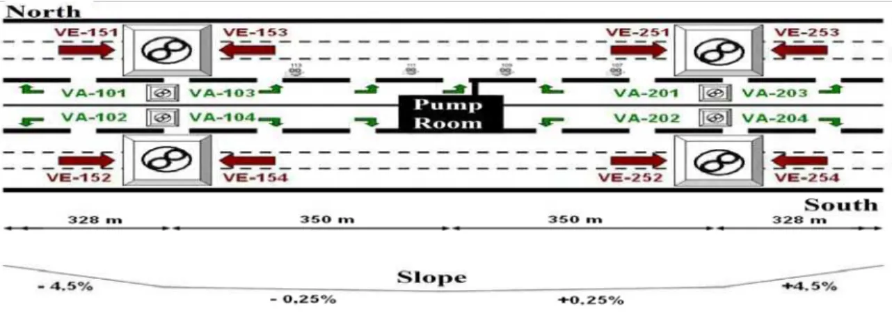
Tunnel Ventilation System
The L.-H.-La Fontaine road tunnel (Figure 1), built in 1964, is located in Montreal, and travels underwater in a north-south direction. The tunnel is 1.8 km long with three lanes in each direction, inside two concrete tubes. Two ventilation towers are located at the ends of the underwater section. A control and monitoring centre for the tunnel is located at the North tower. A central section separates the two tubes. Galleries located in this section are used to supply air along the tunnel length via openings distributed along the walls and these galleries can also be used as evacuation routes. Doors at various locations along the length of the tunnel provide access to the gallery. There are doors between the galleries providing a route to the other roadway. The wall openings have adjustable dampers to ensure uniform air distribution. The side vents are situated in two rows: upper and lower. The lower and the upper rows are located at heights of 1.0 and 3.9 m above the tunnel floor, respectively, and at intervals of approximately 6 m. The two rows of vents are offset by 3 m.
The tunnel ventilation is provided by a semi-transverse ventilation system with local extraction points (Figure 2). The ventilation system is composed of 8 ceiling exhaust fans (4 fans for each roadway – the VE fans) and 8 fans (the VA fans) that supply air through the side vents which are uniformly distributed along one wall for each roadway. All fans are multispeed and can operate in reverse mode. Therefore, fresh air may be supplied by either the ceiling (fans VE151 through VE254), or by fans VA101 through VA204 through the side vents. In the exhaust mode, the ceiling fans VE can operate at half or full capacity, and in the supply mode they can only operate at full capacity. In the supply mode, fans VA can operate at half, two-thirds, or full capacity. In the exhaust mode, these fans can only operate at full capacity.
NUMERICAL SIMULATIONS
CFD models can be used to provide a two- or three-dimensional representation of the domain. The
details of fluid flow and heat transfer provided by CFD models can prove vital in analyzing problems involving far-field smoke flow, complex geometries, and the impact of fixed ventilation flows. As such, CFD techniques can be used to estimate the cost-effectiveness and viability of fire protection strategies
(a) Isometric sketch
(b) Typical cross-section
against introducing design changes. Effects of ventilation, building type and new materials can be evaluated. Moreover, they can be of great value in providing insight into the dynamics of fire behaviour.
CFD models solve the differential equations describing the conservation of mass, momentum, enthalpy, species, etc. within the physical domain of interest. The space and time dimensions are discretized into finite intervals and fluid variables (such as temperature, velocity, gas composition and pressure) and are computed at a finite number of locations at the grid points as a function of time. These variables are connected with each other through algebraic equations derived from their partial differential counterparts by integration over control volumes using the finite difference technique.
Figure 2: Ventilation system of the tunnel
A major difference between CFD models is how the viscosity used in the momentum equation is calculated. The majority of CFD models, e.g. k- ε models (Wilcox 1993), use turbulence models to approximate the turbulent energy and dissipation produced by the fire. This approach results in a solution to an averaged version of the flow equations.
On the other hand, the Large Eddy Simulation (LES) (McGrattan 2000) approach solves the large scales of motion and models the small scales that are assumed to be universal. The LES approach results in an unsteady solution to the Navier-Stokes equations. Because real turbulent flow situations are inherently unsteady, LES methods can have an advantage in modelling turbulent fire-induced flows.
The current research study employs the Fire Dynamic Simulator (FDS) CFD model (McGrattan 2000). FDS is based on the LES approach and solves a form of high-speed filtered Navier-Stokes equations valid for a low-speed buoyancy driven flow. These equations are discretized in space using second order central differences and in time using an explicit, second order, predictor-corrector scheme.
In FDS, fire is represented using the “mixture fraction-based” combustion model. This model directly simulates large-scale convective and radiative transport phenomena. The small length and time scales physical processes are, on the other hand estimated. The actual combustion process in the fire is not simulated. As such, the model inherently assumed that the reaction of fuel and oxygen is infinitely fast (fuel and oxygen cannot co-exist and they will react at any temperature). The local heat release rate is computed from the local oxygen consumption rate at the flame surface.
Parametric Study
FDS was used to investigate the performance of the in-place ventilation strategies. To assess the performance, a parametric study was performed assuming a heat source of 20 MW (equivalent to a bus or truck on fire) in the tunnel. The fire was modelled as an equivalent gasoline pool (NFPA 502 2001). An equivalent gasoline pool with an area of 8 m2 with CO2, CO and smoke flow production rates of 1.5 kg/s, 0.077 kg/s, and 60 m3/s, respectively.
Two fires were simulated: one located at the middle of the tunnel (hereafter called “Mid-Fire” scenario – at a distance in the range of 555 to 615 m from the North Portal) and the other is located near exhaust fans VE151 and VE153 (hereafter called “Exhaust-Fire” scenario – at a distance in the range of 355 to 555 m from the North Portal). These two scenarios are deemed to cover the two main situations probable to occur in the tunnel corresponding to fire occurring inside or outside the middle region of the tunnel. The
parameters examined are the capacity of VA ventilation fans and the percentage opening of the side vents dampers. The maximum fan capacity of VE and VA fans is 227 m3/s.
Mid-Fire scenario simulated cases
One of the project objectives was to use results from the numerical models to improve the side vent damper settings. Currently all dampers are fully open which requires the tunnel supply systems to operate at full capacity. To explore the effect of damper settings and fan operating capacities on the performance of the EVS, six cases were investigated under this fire scenario. They are described in Table 1.
Table 1: Description of Simulated Cases under Mid-Fire Scenario
Fan Operation Capacity (%) Opening Percentage (%)
Case
VE151 VE153 VA103 VA201 Lower Upper
1 E: 100 E: 100 E: 100 S: 100 100 100 2 E: 100 E: 100 E: 100 S: 100 50 50 3 E: 100 E: 100 E: 100 S: 50 100 100 4 E: 100 E: 100 E: 100 S: 100 0 100 5 E: 100 E: 100 E: 100 S: 100 100 0 6 E: 100 E: 100 E: 100 S: 50 0 100 E: Exhaust S: Supply
The parameters examined were the capacity of fan VA201 and the percentage opening of the upper and lower side vent dampers. In Cases 1, 2, 4, and 5, fan VA201 operates at full capacity and in the other two Cases, 3 and 6, the fan runs with 50% capacity. Three sizes of side vents were considered: 100% (fully-opened), 50% and 0% (closed).
In this scenario, fresh air was supplied through the sidewall vents of the galleries of fans VA103 and V201 and hot smoke and fire products were exhausted through the tunnel ceiling fans VE151 and VE153. Fresh air was also drawn through the North and South Portals.
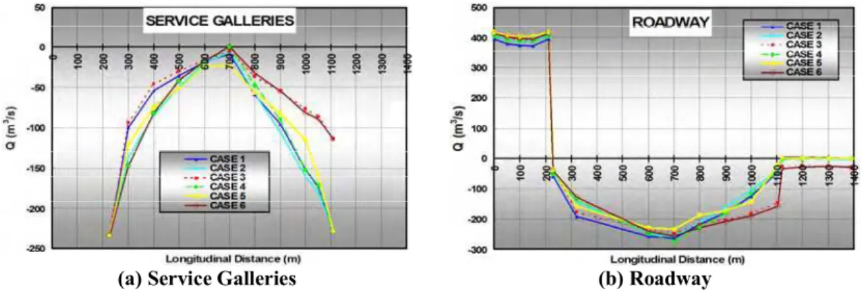
The bulk plots (Figure 3 through Figure 5) show the volumetric flow, temperature and visibility distribution across the tunnel length in the roadway as well as in the service galleries. The bulk values are calculated by averaging the values of an airflow parameter at each cross-section of the tunnel. A positive volumetric flow within the tunnel represents airflow from the North Portal towards the South Portal (against traffic).
(a) Service Galleries (b) Roadway
Figure 3: Bulk volumetric flow across the tunnel (Mid-Fire)
Figure 3 shows the bulk volumetric flow in the roadway and service galleries for the six simulated cases. Fresh air was supplied by fan VA201 through the galleries and entered the tunnel roadway through the fully-opened side vents. Smoke and hot gases were exhausted through ceiling fans VE151 and VE153 and through the side vents to the galleries of fan VA103. Fresh air was also drawn through the North and South Portals. With fan VA201 operating with 50% capacity (Cases 3 and 6), the major impact on the flow
distribution in the roadway occurs at fans VE251 and VE253 (upstream of the fire) and less significant effects took place downstream of the fire.
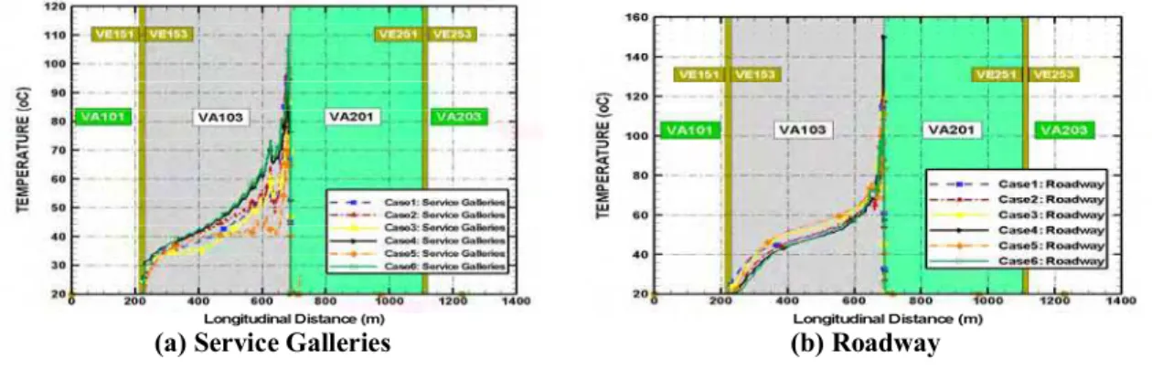
Figure 4 shows the bulk temperatures in the roadway and service galleries for the six cases for the Mid-Fire scenario. The maximum predicted temperatures at the fire location were 130, 120, 129, 150, 121, and 113oC, for the six cases respectively. Case 4 (with the lower vents closed) resulted in the highest predicted temperature. However, Cases 4 and 6 resulted in a relatively faster dissipation of high temperature due to the greater efficiency of the upper vents in extracting hot gases from the tunnel roadway. The reduced supply capacity of fan VA 201, depicted in Case 6, resulted in more flow directed upstream of the fire towards the South Portal. In doing so, the hot gases from the fire were diluted to nearly the ambient environment resulting in a reduced peak temperature and faster dissipation of the temperature downstream of the fire. Moreover, Case 6 offers a favourable evacuation condition with lower air speed in the service galleries of fan VA 201 (Cheung et al 2003).
(a) Service Galleries (b) Roadway
Figure 4: Bulk temperatures (Mid-Fire)
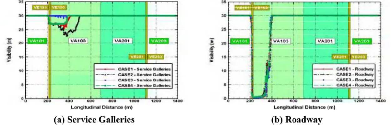
The above-mentioned observations were confirmed in Figure 5, which shows a quick restoration of good visibility (rapid extraction of smoke) downstream of the fire for Cases 4 and 6. The visibility is calculated assuming a value of 2 for the proportionality constant (reflected signs and building components in reflected light, Klote and Milke 2002). It is important to note that even though Case 4 has a favourable visibility condition, it may present a challenge for the movement of the evacuees by introducing a faster airflow in the service galleries of fan VA201.
(a) Service Galleries (b) Roadway
Figure 5: Bulk visibility (Mid-Fire)
Exhaust-Fire scenario simulated cases
Four cases were investigated under this fire scenario. They are described in Table 2. The parameters examined were the capacity of fans VA103 and VA201 and the percentage opening of the upper and lower side vents. In all Cases, except for Case 1, both fans VA103 and VA201 operate with 50% capacity. Two sizes of side vents were considered: 100% (fully-opened) and 0% (fully-closed).
In this scenario, fresh air was supplied through the sidewall vents of the galleries of fan V201 and hot smoke and fire products were exhausted through the tunnel ceiling fans VE151 and VE153 and the sidewall vents of the galleries of fan VA103.
Table 2: Description of Simulated Cases under Exhaust-Fire Scenario
Fan Operation Capacity (%) Opening percentage (%)
Case VE151 VE153 VA103 VA201 Lower Upper
1 E: 100 E: 100 S: 100 S: 100 100 100 2 E: 100 E: 100 S: 50 S: 50 100 100 3 E: 100 E: 100 S: 50 S: 50 0 100 4 E: 100 E: 100 S: 50 S: 50 100 0 E: Exhaust S: Supply
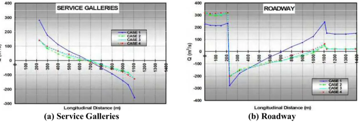
Figure 6 shows the bulk volumetric flow in the roadway and service galleries for the four simulated cases. With fans VA103 and VA201 operating with 50% capacity (Cases 2, 3, and 4), the airflow speeds in the middle region of the tunnel are, in general, higher than those for Case 1 and in the direction of the traffic (South-North). This represents favourable conditions for smoke removal. Also, for the three Cases 2, 3, and 4 more fresh air is withdrawn at the North Portal which helps to trap the smoke close to exhaust fans VE151 and VE153.
(a) Service Galleries (b) Roadway
Figure 6: Bulk volumetric flow across the tunnel (Exhausted-Fire)
Figure 7 shows the centreline temperature profiles for the four cases at different locations across the tunnel. In general, Case 4 (fans VA103 and VA201 operating with 50% capacity and upper side vents are closed) resulted in the lowest predicted temperatures. These predictions are believed to be the result of the fact that the fresh air is supplied at a lower height than the hot layer and thus causes no disturbance to the movement of the smoke and hot gases towards exhaust fans VE151 and VE153.
(a) Service Galleries (b) Roadway
Figure 8 shows similar visibility conditions in the roadway for all cases. However, the four cases produced different visibility conditions in the service galleries of fan VA103. Case 3 (with lower side vents closed) produced almost 30 m visibility throughout the service galleries. Cases 1 and 4 resulted in 25-27 m visibility. Case 2 created slightly lower visibility conditions that extended upstream of the fire.
CONCLUSIONS AND RECOMMENDATIONS
Conclusions
To assess the performance of in-place EVS in the La Fontaine road tunnel, FDS was used to conduct a parametric study for a fire source of 20 MW and for different ventilation and fire scenarios. Based on the parametric study, the following conclusions can be made:
The in-place ventilation strategies for the two fire scenarios, close to the exhaust fans and at the middle of the tunnel, are efficient in clearing hot smoke and fire products from the tunnel and preventing the phenomenon of “backlayering”.
⇒ ⇒ ⇒ ⇒ ⇒ ⇒ ⇒
The airflow velocity in the evacuation passage was estimated to be 14 m/s with VA fans at maximum capacity in supply. It might be difficult to walk against such a high airflow during evacuation. Lower velocities (11 m/s) would facilitate movement in the evacuation passage (Cheung et al 2003).
(a) Service Galleries (b) Roadway
Figure 8: Bulk visibility (Exhausted-Fire)
Lowering the capacity of fan VA in the supply mode would, in addition to facilitating movement in the evacuation passage, improve the visibility downstream of the fire.
In general, it is recommended that the upper vents be opened and the lower vents be fully-closed when the VA fans operate in the exhaust mode. This configuration would result in a more efficient extraction of smoke and hot gases from the tunnel.
It is favourable to have the upper side vents fully-closed and the lower side vents fully-opened while the VA fans operate in the supply mode. This configuration would result in a minimum disruption of the buoyant smoke and hot gas layers.
Recommendations
While indicating earlier that the current procedures are deemed effective in controlling the smoke, in order to further improve the performance of these strategies the following recommendations may be considered:
The ideal situation would be to automate the side vent dampers in order to be able to change their configuration according to the fire location and the scenario used. In turn, this will provide the tunnel operator the maximum flexibility in dealing with different fire scenarios.
While it is suggested that the damper system be automated, this option could be expensive to implement and maintain operational in Canadian weather. An alternative option can be to optimize side vent configurations (opening/closure state) in accordance with the most critical scenarios used. In this option, it is recommended that the upper vents of fans VA101, VA102,
VA104, VA201, VA203 and VA204 be fully closed and the lower vents be fully-opened. For fans VA103 and VA202, it is suggested that the upper vents be fully-opened and the lower vents fully-closed.
⇒ Introduce a duct system that separates the evacuation paths from the ventilation system operations in the service galleries.
ACKNOWLEDGEMENTS
The author acknowledges the NRC’s researchers, Dr. Noureddine Bénichou and Dr. Gary Lougheed, technical staff, Mr. George Crampton and Mr. Don Carpenter, and the staff of the Ministère des Transports du Québec who immensely contributed to conducting the successful in-situ tests.
REFERENCES
NFPA 502 2001. Standard for Road Tunnels, Bridges, and Other Limited Access Highways. NFPA, 1 Batterymarch Park, PO Box 9101, Quincy, MA 02269-9101, USA.
Lacroix, D. 1998. The New PIARC Report on Fire and Smoke Control in Road Tunnels. Third International Conference on Safety in Road and Rail Tunnels, Nice, France, p. 185-97.
Heselden, A J M. 1976. Studies of fire and smoke behaviour relevant to tunnels. Proc. Second International Symposium on the Aerodynamics and Ventilation of Vehicle Tunnels, Cambridge, BHRA, paper J1. McGrattan, K.B., Baum, H.R. Rehm, R.G., Hamins, A. and Forney, G.P. 2000. Fire Dynamics Simulator –
Technical Reference Guide. NISTIR 6467, National Institute of Standards and Technology, Gaithersburg, MD.
Kashef, A.; Bénichou, N.; Lougheed, G.D.; Debs, A. 2003. Numerical modelling of air movement in road tunnels. CFD 2003, the Eleventh Annual Conference of the Computational Fluid Dynamics, Society of Canada (Vancouver, B.C. 2003-05-28), pp. 23-30.
Kashef, A.; Bénichou, N.; Lougheed, G.D.; Debs, A. 2003. CFD simulation of in-situ airflow measurements in road tunnels. 5th International Conference Safety in Road and Rail Tunnels (Marseilles, France), pp. 609-618.
Kashef, A.; Bénichou, N.; Lougheed, G.D.; Debs, A. 2004. Application ff CFD Techniques for Modelling Fire in Road Tunnels. CFD 2004, the Twelfth Annual Conference of the Computational Fluid Dynamics, Society of Canada (Ottawa, ON).
Kashef, A.; Lougheed, G.D.; Bénichou, N.; Debs, A. 2005. Investigation of effectiveness of emergency ventilation strategies in the event of fires in road tunnels. ASHRAE Transactions, 111, pp. 1-14. Klote, J., and Milke, J. 2000. Principles of Smoke management. ASHRAE, Inc., 1791 Tullie Circle NE,
Atlanta, GA 30329.
Innovative Research 1998 .Reference Manual for COMPACT-3D. Innovative Research, Inc., Minneapolis. Wilcox, D.C. 1993. Turbulence Modeling of CFD. DCW Industries, Inc., California 91011.
Cheung, Emil, Chan, Wilson, and Man, Richard 2003. Ventilation Scheme using Saccardo Nozzles. Tunnel Management International, 5th International Conference, Safety in Road and Rail Tunnels, Volume 6, Number 1.