Publisher’s version / Version de l'éditeur:
Canadian Journal of Civil Engineering, 15, 5, pp. 807-814, 1988-10
READ THESE TERMS AND CONDITIONS CAREFULLY BEFORE USING THIS WEBSITE. https://nrc-publications.canada.ca/eng/copyright
Vous avez des questions? Nous pouvons vous aider. Pour communiquer directement avec un auteur, consultez la première page de la revue dans laquelle son article a été publié afin de trouver ses coordonnées. Si vous n’arrivez pas à les repérer, communiquez avec nous à [email protected].
Questions? Contact the NRC Publications Archive team at
[email protected]. If you wish to email the authors directly, please see the first page of the publication for their contact information.
NRC Publications Archive
Archives des publications du CNRC
This publication could be one of several versions: author’s original, accepted manuscript or the publisher’s version. / La version de cette publication peut être l’une des suivantes : la version prépublication de l’auteur, la version acceptée du manuscrit ou la version de l’éditeur.
Access and use of this website and the material on it are subject to the Terms and Conditions set forth at
Thermal stresses in double-glazed windows
Pilette, C. F.; Taylor, D. A.
https://publications-cnrc.canada.ca/fra/droits
L’accès à ce site Web et l’utilisation de son contenu sont assujettis aux conditions présentées dans le site
LISEZ CES CONDITIONS ATTENTIVEMENT AVANT D’UTILISER CE SITE WEB.
NRC Publications Record / Notice d'Archives des publications de CNRC:
https://nrc-publications.canada.ca/eng/view/object/?id=e0f5f36c-130e-409d-8672-e721dbcfe234 https://publications-cnrc.canada.ca/fra/voir/objet/?id=e0f5f36c-130e-409d-8672-e721dbcfe234Ser
TH1
National Research
Conseil national
~ 2 1 d
*I
Councll Canada
de recherches Canada
no.
1577
c. 2
Institute for
lnstitut de
BLDG
Research in
recherche en
Construction
construction
Thermal Stresses in Double-Glazed
Windows
by C.F. Pilette and D.A. Taylor
Reprinted from
Canadian Journal of Civil Engineering
Vol. 15, No.
5, October 1988
p. 807-814
(IRC Paper No. 1577)
L I B R A R Y
T h i s p a p e r
i s
b e i n g d i s t r i b u t e d i n r e p r i n t f o r m by t h e I n s t i t u t e f o r R e s e a r c h i n C o n s t r u c t i o n . A l i s t of b u i l d i n g p r a c t i c e a n d r e s e a r c h p u b l i c a t i o n s a v a i l a b l e from t h e I n s t i t u t e may be o b t a i n e d by w r i t i n g t o t h e P u b l i c a t i o n s S e c t i o n , I n s t i t u t e f o r R e s e a r c h i n C o n s t r u c t i o n , N a t i o n a l R e s e a r c h C o u n c i l o f C a n a d a , O t t a w a , O n t a r i o ,KlA
0R6. Ce document e s t d i s t r i b u 6 s o u s forme d e t i & - 8 - p a r t p a r 1 ' I n s t i t u t de r e c h e r c h e e n c o n s t r u c t i o n . On p e u t o b t e n i r une l i s t e d e s p u b l i c a t i o n s d e 1 ' I n s t i t u t p o r t a n t s u r les t e c h n i q u e s ou les r e c h e r c h e s e n m a t i e r e d e b a t i r n e n t e n B c r i v a n tB
l a S e c t i o n d e s p u b l i c a t i o n s , I n s t i t u t d e r e c h e r c h e e n c o n s t r u c t i o n , C o n s e i l n a t i o n a l d e r e c h e r c h e s d u Canada, O t t a w a ( O n t a r i o ) , KIA OR6. - - - - -Thermal stresses in double-glazed windows
C. F. PILETTE
Department of Civil Engineering and Applied Mechanics, McGill University, 81 7 Sherbrooke Street West, Montreal, Que., Canada H3A 2K6
AND D. A. TAYLOR
Institute for Research in Construction, National Research Council of Canada, Montreal Road, Ottawa, Ont., Canada KIA OR6
Received March 2, 1987
Revised manuscript accepted March 21, 1988
Using finite elements, the authors studied temperatures and thermal stresses in 1.41 m wide by 2.12 m high sealed double-glazed windows of 6-mm glass with a 12-mm air space between the panes. The purpose was to find factors significantly influencing thermal stresses. Three types of commercially used windows subject to winter conditions (day and night) were analyzed: both panes clear glass; outer pane heat absorbing and inner clear; and outer clear with a metallic film on its room-side surface and inner clear. A sensitivity analysis included variations in size of window, gasket and sealant stiffnesses, frame absorption, solar heat flux, exterior air film conductance, and outdoor air temperatures (- 5 and -25°C). Further, the influence of horizontal and vertical shadows was studied. For the calculation of thermal stresses, the authors found that the windows could be analyzed pane by pane rather than as a three-dimensional structure. Solar radiation and particularly shadows had a major influence on thermal stress, while window size and aspect ratio did not. A case study in which the predicted temperatures were compared with those measured by Sasaki in 1974 showed good agreement and indicated that a simpler steady-state rather than transient thermal analysis gave a close estimate of the temperature difference between the centre and edges of panes for design against thermal breakage.
Key words: window breakage, thermal stresses, glass temperatures, shadows, double-glazing, finite elements.
A l'aide des ClCments finis, les auteurs ont CtudiC les tempCratures et les contraintes thermiques de vitrages doubles scellks de 1,41 m de largeur sur 2,12 m de longueur, avec vitre d'une Cpaisseur de 6 mm et lame d'air de 12 mm entre les vitrages. L'objectif Ctait de dCcouvrir les facteurs qui influent de facon significative sur les contraintes thermiques. Trois types de fenstre d'usage commercial, sournis aux conditions hivemales (nuit ct jour). ont CtC analysCs : deux vitrages en verre clair; vitrage extCrieur absorbant la cbaleur et vitrage interieur en verre clair; vitrage extCrieur en verre clair avec film mCtallique sur la surface du cBtC interieur. et vitrage intheur en v e m clair. Une a n a l y e de sensibilitk a port6 sur les variations de la dimension des fenktres, la rigiditt de la garniture et du pmduit d'etanchtitk, l'absorption du cadre, le flux de chaleur solaire, la conductance du film d'air
extirieur et les temp5aures de l'air exkkiems (-5°C et -25°C). En outre, l'influence des ombres horizontales et verticales a
C
e
CtudiCe. En ce qui conceme le calcul des contraintes thermiques, les auteurs ont constat6 que I'analyse des fenetres pouvait stre faite vitrage par vitrage, par opposition a l'analyse de structure tridimensionnelle. Le rayonnement solaire et surtout les ombresont eu une influence majeure sur la contrainte thermique, contrairement ?la dimension des fenstres. Une Ctude de cas a permis de i
constater une bonne correspondance entre les temperatures de calcul et celles mesurCes par Sasaki en 1974; elle a en outre rCvC1C qu'une analyse thermique en rCgime permanent plutBt qu'en Ctat transitoire donnait une estimation plus juste de la diffkrence de temperature Cntre le centre et le pourtour des vitrages, ceci dans le but de prCvenir le bris thermique.
Mots cles : bris de fen&tre, contraintes thermiques, tempkratures de vitrage, ombres, vitrage double, ClCments finis.
[Traduit par la revue]
Can. J . Civ. Eng. 15.807-814 (1988)
Introduction
Stresses leading to window breakage arise in several ways. In sealed multiple-glazed units, pressure differences between the sealed air space and the surrounding air occur due to changes in temperatures and barometric pressures; they may result in significant bending stresses (Solvason 1974). Wind pressures also induce flexural stresses which in severe conditions may cause failures. Other causes of breakage, such as Impact, incorrect @zing, or reduced pressure between panes because of nitrogen absorption of the dessicant, have been summarized elsewhere (Pilkington 1965;
Barry
1986; Solvason 1981).Although design charts for windows are generally based on wind pressures, another factor contributing to window breakage in Canada is thermal stresses due to the differences in temperature between the edges and centres of glass panes during cold weather. The resulting tensile stresses at the edges of NOTE: Written discussion of this paper is welcomed and will be received by the Editor until February 28, 1989 (address inside front cover).
windows can be larger than those produced elsewhere on the glass by lateral pressures. In addition, the maximum flexural stresses induced by lateral pressures occur near the centres of panes or near their comers, and have little effect on tensile stresses at the edges. Edge stresses are important because they combine with edge flaws in limiting the ultimate strength of windows.
When a window is exposed to solar radiation the temperature rises over its central area. The edge temperatures increase more slowly, partly because the edges are shaded from radiation and partly because of the relatively large heat capacity of the frame. Such temperature differentials produce compression stresses at the centre of the window and tensile stresses around the edges. A similar effect will result from partial shading of the glass by overhangs and deep mullions. If the glass has damged or poorly cut edges or is already stressed from other causes, the added thermal stresses may cause failure.
Temperature differentials in double-glazed windows are increased by thermal bridging. The spacer at the edges separating the panes of glass is usually of metal. It conducts heat
808 CAN. J. CIV. ENG
readily from the edges of the glass to outside, leaving the edges, especially of the inner pane, colder than the centre.
Glass temperatures and thermal performance of windows have been studied for some years. Sasaki (1971, 1973) examined the factors affecting the edge temperatures of sealed double-glazed units and measured the profiles of glass tempera- tures. In another study, Sasaki (1974) took measurements to compare the maximum solar breakage potential of seven types of windows. Jonsson (1984) and Standaert (1984) presented analyses of heat transfer through window frames using finite element and finite difference methods.
Thermal stresses and thermal fracture of windows made with coloured glass or surface coatings to limit solar radiation have been investigated previously. Pilkington (1964, 1972) pub- lished guidelines for the design of glazing units to prevent thermal fracture. Designs were based on temperature differ- ences between the centres and the edges of single- and double-glazed units. Measurements of thermal strains due to differential heating of glass were performed by Blight (1974) and Mai and Jacob (1979, 1980). They also studied the resulting fracture patterns. Stahn (1980) described a finite element analysis of thermal stresses in which a systematic examination of the contributions of outdoor shading patterns to the magni- tude of thermal stresses was carried out. He represented the drop in temperature between the hot centre and cool edges by a stepwise temperature function. As well, theoretical formulas to calculate thermal stress in plates under various temperature distributions were presented by Goodier (1957) and Boley (1964).
The work forming the basis of this paper was undertaken to develop an analytical approach for obtaining temperature distributions and the resulting thermal stresses in windows. This paper identifies the factors influencing thermal stresses in windows with the aim of helping designers to avoid cases of thermal breakage in practice.
Heat transfer through double-glazed units
Useful estimates of thermal stresses in windows are achieved only if reliable temperature distributions are available (Boley 1964). Field measurements of temperatures involve painstaking instrumentation and may require several years of monitoring to record climatic conditions resulting in significant glass stresses (Sasaki 1974). Another approach, physical modelling, would require a cold-room facility. In this investigation, temperature distributions were computed using finite element techniques. Heat transfer model
Heat transfer analyses were performed on three commercial types of sealed double-glazed windows 1.41 m wide by 2.12 m high (area 3 m2 and aspect ratio 1.5) (Table 1). Reasonable physical properties were assumed. The absorption of solar radiation was taken to be 12% for clear glass, 50% for heat-absorbing, and 60% for clear glass with a metallic film (Pilkington 1972). Reflection of solar radiation by the outer pane was about 10% for windows 1 and 2 and 25% for window 3.
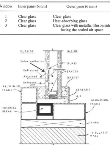
A drawing of the aluminum frame in which the units were mounted is shown in Fig. 1. The frame includes a thermal break. The physical properties of the materials, the thermal conduc- tivity, density, and specific heat, were obtained from the ASHRAE handbook (American Society of Heating, Refrigerat- ing and Air-Conditioning Engineers 1981). These are design values. As the absorptance of solar radiation by aluminum ranges from 40 to 65%, a value of 50% was chosen for the
. VOL. 15, 1988
TABLE 1. Type of glazing
Window Inner pane (6 mm) Outer pane (6 rnm)
1 Clear glass Clear glass
2 Clear glass Heat-absorbing glass
3 Clear glass Clear glass with metallic film on side
facing the sealed air space
O U T S I D E A L U M 1 F R A M E A L U M I N U M T H E U M S R E A K I N S U L A T E D
FIG. 1. Schematic drawing of the glazing unit as modelled.
frame. All units were assumed to be sealed with a 6-mm thickness of commercial sealant backed by a 12-mm aluminum spacer containing a dessicant, and held with 12-mm solid neoprene gaskets on either side of the unit. An air film conductance of 34 w/(m2."C) for the outside and 8 w/(m2."C) for the room-side surface was used. Thermal resistance of the sealed air space was calculated according to the 1981 ASHRAE handbook. The resistance of the air space in window 3 (Table 1) was about twice as much as in windows 1 and 2 due to the difference in effective emittance of the metallic film compared to the glass surface. The inside (room) air temperature was held constant at 20°C, whereas the outside air temperature was assumed to be -5OC which represents a mild winter condition. Tables for elevation, azimuth, and intensity of the sun were used to calculate the amount of solar radiation received by a vertical window in the Ottawa-Montreal area (Stephenson 1967). A correction was made to include the reflection of solar radiation by the ground, which ranges from 15 to 50% (Hutcheon and Handegord 1983). Such conditions represent a typical winter situation to which windows 1, 2, and 3 could be subjected. The influence of colder temperatures was investigated as well. Finite element analysis of heat transfer
Two steady-state heat transfer analyses were performed on each type of glazing (Table 1) using NISA, a general purpose finite element program (Engineering Mechanics Research Cor- poration 1983). The filst analysis simulated night conditions with no solar radiation; and in the second, an arbitrary net solar heat flux of 1000 W/m2 (including the ground reflection) was applied to the unit to simulate day conditions. Such radiation is
PILE'ITE AND TAYLOR 809
I
(0) WINDOWS 1 AND 2 I
1
INNER PANE'
1 I-
. . ... OUTER PAHE - --
OAT - WNDOW 2 DAY - W I H O 6 W 1 I-.,.
'-.*-
- - . . - " _ _ _ _ _ _ _ _ _ _ _ _ _ . ~ . . ~ ~ ~ ~ . ~ ~ n n n n n n n n n n . * . ~ . ~ * . . ~ ~ *- .
--.
NIGHT-
WIHUDW3 1 AH0 1-
---.*---...*....
-.---
-
-
1 I I I I I I I
35 0
I I
V) (b) WINDOW 3 INNER PANE
30.0 . . . . . OUTER PANE
0
cj 25.0
-
-10.0 I I I I I I I I
0 0 0 0 0.025 0 050 0.075 0.100 0 125 0.150 0.175 0.200 0.225
DISTANCE FROM GLASS EDGE, rn
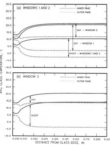
FIG. 2. Temperature gradients of glass subjected to solar radiation. Lower centre temperatures of the outer pane result in compressive edge stresses and relatively low tensile stresses in the central area. typical of the noon value on a clear day for the Ottawa-Montreal region during the month of January.
The resulting temperature profiles for the inner and outer panes of each type of glazing are presented in Fig. 2. The outer panes of all units had no potential for thermal breakage, day or night, since the centres of the panes were either about the same temperature as the edges (no thermal stresses) or the centres were colder than the edges, resulting in compressive stresses at the edges and low tensile stresses at the centres. For the night condition, a temperature differential on the inner pane of 4.2"C on windows 1 and 2 and 7.9"C on window 3 were obtained. This difference is attributed to the metallic film in window 3 which reduces the effective emittance of the air space. As this reduces the heat loss from the room it increases the temperature of the inner pane. These results are comparable to those obtained by Sasaki (1971, 1973) under similar conditions.
During the day, the inner panes of windows 1 , 2 , and 3 were subject respectively to temperature diflerentials (in the plane of
the glass-between centres and edges) of 9.5, 7.8, and 6.9"C.
Because the outer pane of window 2 is heat absorbing, it gets hotter than the clear outer pane of window 1 and conducts more heat to its edges (Fig. 2a). This reduces the temperature differential compared to window 1. The reflective film on the inside face of the outer pane of window 3 has the same effect (Fig. 2b). Although window 3 has a higher absorptance than
window 2 (60% rather than 50%), the lesser temperature
differential of window 3 is attributed to the higher reflectivity of its outer pane.
Temperature gradients across the thickness of the outer panes were obtained for day-time conditions. A value of 1°C was
recorded for window 1 and 2°C for windows 2 and 3. For all
other curves in Figs. 2a and 2b the temperature gradients across the thickness were found to be less than 0.4"C.
It was observed that the edge effect on temperature profiles
was limited to about the first 100 rnm from the edge cover during
the day and 50 mm at night. Similar values were shown by Mai and Jacob (1979) and Sasaki (1971).
Heat transfer sensitivity analysis of window 2
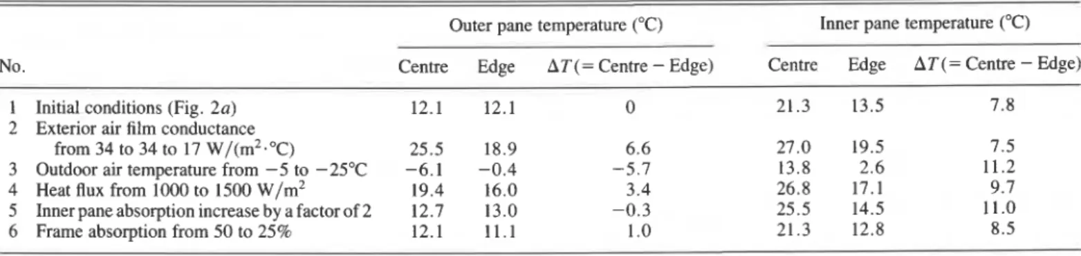
A sensitivity analysis of window 2 was conducted to investigate the behaviour of the heat transfer model under slight modifications during day exposure (Table 2). The standard conditions were exterior air film conductance, 34 W/(m2-"C); outdoor air temperature -5°C; incident solar heat flux, 1000 W/m2; heat absorption of inner pane, 12% of solar radiation passing through the sealed air space; and heat absorption of aluminum frame, 50%. A reduction in heat loss due to a decrease in the exterior air film conductance from 34 to 17 W/(m2."C), which represents a "low wind" condition (still air is about 8 w/(m2."C)), had little effect on the temperature differential of the inner pane: edge and centre both increased by about 6°C. As the inner pane is insulated by the exterior air film, the outer pane, and the sealed air space, changes to the exterior air film conductance are of relatively lesser importance than for the outer pane. The outer pane was, therefore, much more sensitive to the reduction in heat loss. The centre temperature increased but because the edge temperature did not increase as much, the temperature differential increased from 0 to 6.6"C. A
drop in outdoor air temperature from - 5 to - 25°C increased the
temperature differential of the inner pane from 7.8 to 1 1.2"C, while an increase in the solar heat flux from 1000 to 1500 W/m2 (high solar radiation, including ground reflection) increased the temperature differential of the outer from 0 to 3.4"C and the inner from 7.8 to 9.7"C (Table 2). Arbitrarily the amount of solar radiation heating the inner pane was increased by a factor of 2. This simulated radiation reflected back against the inner pane by the drapes and blinds. The net result, in this case, was an increase in temperature differential on the inner pane from 7.8 to 1 1°C. Finally, a reduction in solar absorption of the frame from 50 to 25% reduced the edge temperature of the unit (i.e., increased the temperature differential) by just under 1°C on average.
Some of the changes from initial conditions in Table 2, such as numbers 3 and 4, represent changes to loads on the finite
element model, whereas the remainder 2, 5, and 6 represent
changes to the model itself. The resulting temperature differen- tials, AT, therefore cannot strictly be added together to give the
correct AT as the combinations are not necessarily linear.
Nevertheless, such addition will give about the right answer. Thus if all the conditions unfavourable for the inner pane of window 2 acted together (Table 2), its temperature differential could increase from 7.8"C to as much as 17"C, approximately, without accounting for the detrimental influence of shadows. On the other hand, the outer pane was mainly affected by the change in outdoor air film conductance and the solar heat flux due to direct and reflected solar radiation, which could result in an increase in temperature differential from 0°C to as much as about 11°C. The behaviour of window 2 under these various conditions is in accordance with Sasaki (1974).
Effects of partial shading on temperatures
The effects of partial shading on glass temperature were investigated. The resulting differential heating was applied in a three-dimensional heat transfer model of a sealed double-glazed window. Figure 3a presents a plan view of the isothermal
810 CAN. J. CIV. ENG. VOL. 15, 1988
TABLE 2. Thermal sensitivity analysis of window 2
No.
Outer pane temperature ("C) Inner pane temperature ("C) Centre Edge AT(= Centre - Edge) Centre Edge AT(= Centre - Edge)
1 Initial conditions (Fig. 2a) 12.1 12.1 0 21.3 13.5 7.8
2 Exterior air film conductance
from 34 to 34 to 17 w/(m2."C) 25.5 18.9 6 . 6 27.0 19.5 7.5 3 Outdoor air temperature from -5 to -25°C -6.1 -0.4 -5.7 13.8 2.6 11.2 4 Heat flux from 1000 to 1500 W/m2 19.4 16.0 3 . 4 26.8 17.1 9.7 5 Inner pane absorption increase by a factor of 2 12.7 13.0 -0.3 25.5 14.5 11.0 6 Frame absorption from 50 to 25% 12.1 1 1 . 1 1 .O 21.3 12.8 8.5
-
(0) NORMALIZED ISOTHERMAL CONTOURS-
a -0.10-0.05 0.00 0.05 0.10 0.15 0.20 DISTANCE X FROM THE SHADOW LINE, m (b) GLASS TEMPERATURE
35.0
-10.0
0.0 0.2 0.4 0.6 0.8
WIDTH OF WINDOW, m
generate a profile of the steady-state glass temperatures in any size of window subject to any shadow configuration. Figure 3b shows the thermal condition of a 1-m wide window (like window 2 in Table 1) derived in this way.
Case study: thermal behaviour of a sealed double-glazed window
Seven sealed double-glazed units were monitored by Sasaki (1974) to determine the effect of solar radiation and outdoor air temperature on their potential for solar breakage. The authors performed a steady-state and transient heat transfer analysis on one of Sasaki's windows in order to investigate the ability of finite element techniques to predict the thermal behaviour of windows under real exposure conditions. The window selected showed a measured temperature differential on both panes.
The unit was composed of two panes of clear glass with a reflective metallic film on the room side of the outer pane (similar to window 3). It was 0.74 m wide by 2.26 m high and was glazed in an aluminum frame (similar to Fig. 1) facing 25 degrees east of south. Temperature measurements were taken on January 27, 1972. According to Sasaki, the net absorptance was 45% for the outer and 5% for the inner pane. The indoor air temperature was 21°C while the outdoor air temperature was
- 19°C for most of the day. The air film coefficients were calculated from the glass temperature at the centre of both panes at night to be 8 and 10 W/(m2."C) for inside and outside respectively. These values were assumed to remain constant throughout the day. The latter figure is significantly les than the design value (34 w/(m2. "C)). The solar intensities, at different times of the day, were obtained from Stephenson (1967) and a ground reflectance of 20% was estimated for the surroundings.
!.o The results of the finite element analyses are presented in
Figs. 4a and 4b. During the first hour after sunrise, the FIG. 3. Effect of partial shading on temperature gradients.
contour lines produced by the shadow illustrated. The tempera- ture distribution was normalized to an increase of 1°C from the shaded to sunlit area. The portion of the window shown was located far enough from the edges to avoid their effects. The normalized temperature profile presented in Fig. 3a is typical for the inner and outer panes of windows 1, 2, and 3. It is apparent that most of the increase in temperature occurs in a region about 100 mm wide on either side of the shadow lines, which is consistent with the results of Blight (1974) and Stahn (1980). The steady-state temperatures of the shaded and sunlit areas away from the shadow lines were found to be those of the night and day conditions presented in Fig. 2. The temperature profile at X = Y = 0.2 m in Fig. 3a can be used with Fig. 2 to
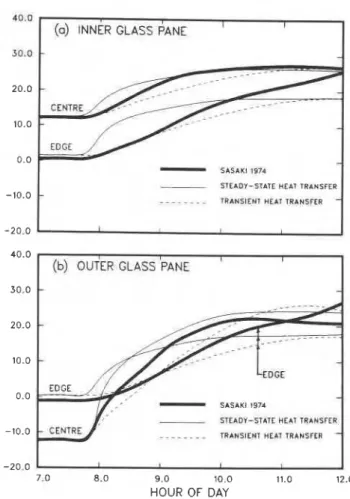
steady-state heat transfer analysis showed a steep increase in glass temperatures whereas the transient analysis indicated a smoother rise. As expected, both analyses converged to the same temperatures after some hours of sun.
Because of the low air film conductance of 10 w/(m2."C), the outer pane was subjected to a positive temperature differen- tial (giving tensile edge stresses) for part of the morning. This is contrary to the results obtained using 34 W/(m2."C) (Fig. 2b). According to Sasaki (1974), surface temperatures that are determined by thermocouples in sunlight are always in error, since the absorption of solar radiation by the thermocouple differs from the absorption by the surrounding glass. Therefore, his measurements of the central temperatures as shown in Figs. 4a and 4b are about 1 and 3°C too high for the inner and outer panes, repectively. As the sun moves across the sky, discrepan- cies are also noticed between the measured and calculated tem-
PILElTE AND TAYLOR 81 1
6.0 I I I I
(0) INNER GLASS PANE I I
-
-
-
-
5 1 5 A K 1 I974STEADY-STATE HEAl TRANSFER - - - - - . . _ l R A N 5 t E N 7 HEAl TRANBFCR I
-20.0
7.0 8.0 9.0 10.0 11.0 12.0 HOUR OF DAY
(b) OUTER GLASS 'PANE I I
-
-
--- -J-
-EDCC-
-
SASAKt 197*-
SEADY-STATC HE81 TRANSFER- -. -. -. . TRANSIENT HEAT TR4HSFFR
-
I I I
FIG. 4. Glass temperature history from 7:00 a.m. until noon.
peratures at the edges (Figs. 4a and 4b). Again, these differences are likely due to direct sunshine on the thermocouples.
If Sasaki's curves of central and edge temperatures are adjusted downwards to account for these measurement "errors," the comparison between his results (1974) and those from the transient heat transfer analyses are improved. Thus the transient heat transfer analysis provides a reasonable way of modelling the thermal behaviour of windows. The steady-state analysis, though not as thorough, is cheaper and easier to use, however, and predicts nearly the same temperature differentials between the edges and the centres of both glass panes throughout the day.
Thermal stresses in double-glazed units
Finite element stress model
The thermal stresses induced by temperature gradients in double-glazed units were calculated using the same finite element program. A three-dimensional model of the frame and the glass was generated to calculate stresses (Fig. 1). The window modelled was 1.41 m wide by 2.12 m high with a 20-mm edge cover for a total glass area of 3 m2 and an aspect ratio of 1.5. The aluminum frame surrounding the edges was assumed to be fixed against rotation and translation, allowing
only the neoprene gaskets and the glazing unit to deflect under
thermal loads. Slipping of the gaskets along the frame and the glass was not allowed. The glass plates were modelled as thin shell elements bounded by three-dimensional solid elements representing the sealant and the gaskets. The aluminum spacer, having relatively low torsional and bending stiffnesses, was represented in such a way that only axial forces were transmitted between the panes.
OIII
-
W I N D O W 1I
I
NIGHT - WlUDOWS 1 AND I
1
1
"."
0 0 0.5 1.0 1.5 2.0
DISTANCE ALONG VERTICAL EDGES OF WINDOW, m
FIG. 5. Thermal stresses on the inner panes induced by temperature
gradients shown in Fig. 2.
Material properties
A static stress analysis was performed assuming linear elastic
behaviour of all materials. For the glass, Young's modulus, Poisson's ratio, and the coefficient of linear thermal expansion
were taken to be 70 GPa, 0.22, and 8 x ~ o - ~ / " c respectively
(McLellan and Shand 1984). The sealant was assumed to have a Young's modulus of about 1 MPa in accordance with Karpati (1972) and Anderson (1985), and a Poisson's ratio approaching 0.5. Neoprene gaskets were assumed to have about the same properties as the sealant (American Society for Testing and Materials 1976).
Results from thejnite element analysis
The temperature profiles in Fig. 2 were applied as inputs to the finite element stress model. As noted previously, only the inner pane was subjected to considerable tensile thermal stresses at the edges. High tensile stresses were obtained near the edges of windows 1 , 2 , and 3, as shown in Fig. 5, whereas the central portion of the glass was characterized by low compressive stresses. The maximum tensile stresses along the short and long edges are practically identical.
The bending stresses, due to the different average tempera- tures of each pane and temperature differences across each pane thickness, were found to be very low, less than 0.02 MPa. However, those in the outer pane were found, as predicted by Timoshenko and Goodier (1951), to be about 0.28 MPa, which indicates a simply supported edge condition.
Profiles of tensile stresses along the edge of the inner pane are presented in Fig. 5. The maximum tensile stress is directly proportional to the temperature differential between the hot centre and cool edges.
Thermal stress sensitivity analysis of window 2
The structural behaviour of the glazing unit under thermal loads was investigated by means of a sensitivity analysis in which properties of its components were varied one at a time. Thermal contraction or expansion of the unit as a whole induces shearing stresses in the gaskets. Consequently, tensile or compressive forces are produced at the edges of the glass. The contribution of this stress field to the maximum tensile stress was less than 1%. An increase in the gasket modulus from 1 to 100 MPa was still not enough to create a significant change. The effect on stresses of rotation and deflection of the frame was not studied.
VOL. 15, 1988
812 CAN. J. C N . ENG.
SHADOW A SHADOW B SHADOW C
FIG. 6. Shadow configuration used on the 1.41 m by 2.12 m glass
window. There are five vertical shadows (0, 200, 300, 400, and 500
mm wide) for each of A, B, and C. All dimensions are in millimetres;
*
indicates 0 to 500 mm.
to larger thermal expansion than the outer. The change in dimensions of the glass causes shearing stresses in the sealant, producing compressive and tensile forces at the edges of the inner and outer panes respectively (Wilson and Solvason 1962). Such stress fields were also found to be insignificant. However, an increase from 1 to 100 MPa in Young's modulus of the sealant reduced the maximum tensile edge stress in the inner pane by 7%. The increase in stiffness barely increased the bending moment in the inner pane.
Finally, the aluminum spacer had very little effect on the distribution of thermal stresses. Its ability to transmit deforma- tion from one pane to another was very small. The sensitivity analysis showed that thermal stresses in either pane of glass are practically unaffected by the stiffness of the gasket, the spacer or the sealant (Fig. 1). For comparison, a second model of the inner pane only using plane stress elements gave thermal stresses within 1% of those computed using the three- dimensional model. Therefore, for stress analysis only, compu- tational effort can be drastically reduced by neglecting the iilfluence of the various elements connecting one pane to another. Each pane can be analyzed individually, assuming plane stresses. A two-dimensional model was used in the remainder of the paper.
Effects of window dimensions
As described earlier, thermal stress analyses were conducted for a pane of dimensions 1.41 m by 2.12 m having an area of 3 m2 and an aspect ratio of 1.5. As well the influences of the area and aspect ratio on the magnitude of the thermal stress were investigated. Three areas were selected: 2,3, and 4 m2. For each of these, three aspect ratios were chosen: 1, 1.5, and 2. Thus a total of nine different sizes of windows were analyzed covering the sizes commonly used in commercial buildings. The thermal load (no shadows) and the 20-mm edge cover were kept constant for each size of glass. The analysis showed that the physical dimensions of the glass appeared to have no effect on the magnitude of thermal stresses. They will have an influence on thermal breakage, however; as a large pane stressed to the same level as a small one will be more likely to break because of the increased probability of finding a "fatal flaw" in the extra area or length of edge under high stresses.
Effects of shadows
Thermal stresses are induced not only by differential heat losses between the edges and the centre of a window but also by differential heating due to partial shading (Fig. 3b). A detailed study of the effects of shadow configuration on thermal stresses was undertaken. Thermal loads produced by partial shading were applied to a 1.41 m by 2.12 m window. Only the inner
S T R E S S . M P o S T R E 5 5 M P o
0 000 1 416
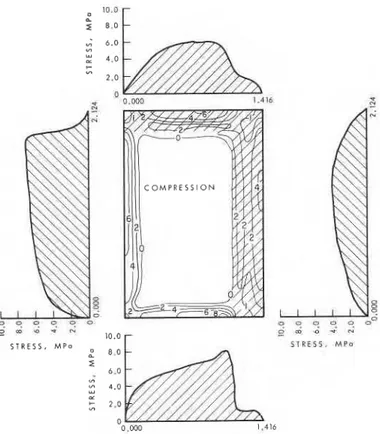
FIG. 7. Principal tensile stress contours and the corresponding edge
stress profiles for window 1. The top shadow was 200 mm and
right-side shadow was 300 rnm (B in Fig. 6). The outside temperature
was -5°C and inside 20°C; air film conductance was 34 w/(m2."c) outside and 8 w/(m2."C) inside; and heat flux was 1000 w/m2. panes of windows 1, 2, and 3 were studied, since very small tensile thermal stresses occur on the outer pane (according to Fig. 2). To reduce computational efforts, a plane stress condition was assumed, thus neglecting the edge restraints on the glass.
Figure 6 shows the three types of shadow configuration selected. A 200 and 400 mm horizontal shadow width was constant for shadow B and C respectively. The simulation of the sun moving across the sky was done by a vertical shadow width of 0, 200, 300, 400, and 500 mm. The corresponding two-dimensional temperature profiles were synthesized from Figs. 2 and 3a resulting in 15 profiles similar to those in Fig. 3 b.
An example of stress contours and corresponding profiles of edge stresses is presented in Fig. 7. It was produced by applying a shadow width of 200 mm at the top and 300 mm at the right side of window 1. The maximum edge stresses obtained in Fig. 7 apply only to the shadow configuration used.
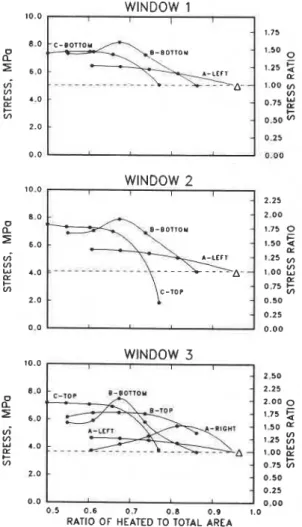
Figure 8 summarizes the maximum edges stress obtained for each type of shadow as a function of the ratio of the sunlit to total area. The curves are described by two parameters: the type of
shadow configuration (A, B, or C) and the location of the
maximum edge stress (top, bottom, left, or right edge). These curves were chosen to show an envelope of the highest tensile stresses for each type of window. A stress magnification scale, on the right side of each graph, shows the relative stress increase
when compared to the "no shade" case represented by a A
symbol (5% of the window area is under the frame). As depicted in Fig. 8, the location and the magnitude of the maximum-stress are functions of both the type of window and the shadow configuration used. All windows exhibited the same shape of
PILE'ITE AND TAYLOR 813
10.0
,
WINDOW 1I I I
4. Three-dimensional effects in a double-glazed window are negligible, i.e., in-plane forces and bending moments are not transmitted in any significant way from one pane to another. As a consequence of this, stresses produced by temperature differentials between edges and centres can be calculated separately for each pane of glass.
5. Temperature gradients through the glass thickness are small and produce bending stresses which can be neglected.
Acknowledgements 10.0 WINDOW I 2 I 2.25 WINDOW 3
7
2.50'
0.0 0.5 0.6 0.7 0 . 8 0.9 1.0RATIO OF HEATED TO TOTAL AREA
FIG. 8. Effect of shadow configuration (from Fig. 6) on edge stress. The dashed line corresponds to thermal stresses without shadows. stress envelope, which is characterized by an increase in stress as the area heated by the sun decreases to about 213 of the total area.
Conclusions
Heat transfer
1. A steady-state heat transfer analysis gives almost the same temperature differential in the glass as the more difficult, and expensive, transient analysis.
2. The temperature differential on the outer pane is greatest for low exterior air film conductance, mild outdoor tempera- tures, and high solar radiation.
3. The temperature differential on the inner pane is greatest for high exterior air film conductance, low outdoor air tempera- ture, high solar radiation, and interior blinds.
Thermal stresses
1. Maximum thermal stresses occur along the edges of the glass. In particular, when there are shadows o n the glass, the maximum stresses occur where the shadow line intersects the edges.
2. Thermal stresses rise as the portion of area shaded increases to about 113 of the total area. Shadows produced by deep mullions and horizontal overlaps should be kept to a minimum.
3. Thermal stresses d o not depend on the geometry of the window for the range of aspect ratios (1.0-2.0) and areas (2.0-4.0 m2) considered.
The authors would like to express their appreciation for assistance and comments from W. A. Dalgliesh, R. P. Bowen, and S. A. Barakat of the Institute for Research in Construction and from C. J.
Barry
formerly of Ford Glass in Toronto. AMERICAN SOCIETY OF HEATING, REFRIGERATING AND AIR-CONDI-TIONING ENGINEERS. 1981. Design heat transmission coefficients.
In ASHRAE 1981 fundamentals handbook. Atlanta, GA, pp. 23.2-23.32.
AMERICAN SOCIETY FOR TESTING AND MATERIALS. 1976. &xdaIIt technology in glazing systems. Special Technical Publication 638, Philadelphia, PA.
ANDERSON, J. B. 1985. A method for finding engineering properties. Journal of Engineering Mechanics, lll(7): 882-892.
BARRY, C. J. 1986. Incorrect glazing exaggerates stresses on sealed I.G. units. Glass Digest, March 15, pp. 101-106.
BLIGHT, E. G. 1974. Thermal strains and fracture of building glass. First Australian Conference on Engineering Material, Sydney, Australia, pp. 685-700.
BOLEY, B . A. 1964. Estimate of errors in approximate temperature and thermal-stress calculations. Proceedings of the Eleventh Internation- al Congress on Applied Mechanics, Munich, West Germany, pp. 586-596.
ENC~INEERING MECHANICS RESEARCH CORPORATION. 1983. Numeri- cally integrated elements for system analysis (NISA). Release 83.1.
Edited by M. D. Mathers. Engineering Mechanics Research Corporation, Troy, MI.
GOODIER, J. N. 1957. Thermal stress and deformation. Journal of Applied Mechanics, 24(3): 467-474.
HUTCHEON, N. B., and HANDEGORD, G. 0.1983. Building science for a cold climate. Wiley, Toronto, Ont.
JONSSON, B. 1984. Heat transfer through windows: influence of spacers, casements and frames. Proceedings, Windows in Building Design and Maintenance, Goteborg, Sweden, 13-15 June, pp. 427-432.
KARPATI, K. K. 1972. Mechanical properties of sealants: 11. Behaviour of a silicon sealant as a function of rate of movement. Journal of Paint Technology, 44(569): 58-66.
MAI, Y. W., and JACOB, L. J. S. 1979. Thermal fracture of building glass subjected to solar radiation. Proceedings, Third International Conference on Mechanical Behaviour of Materials, Cambridge, United Kingdom, Vol. 3, pp. 57-65.
1980. Thermal stress fracture of solar control window panes caused by shading of incident radiation. Materiaux et Constructions, 13(76): 283-288.
MCLELLAN, G. W., and SHAND, E. B. 1984. Glass engineering handbook. McGraw-Hill Book Company, New York, NY, Chap. 2, pp. 2.1-2.55.
PILKINGTON. 1964. The fracture of glass by solar radiation. Pilkington Brothers Limited, Glass and Windows Bulletin, No. 4, pp. 1-3.
1965. The fraction of glass by mechanical loads. Pilkington Brothers Limited, Glass and Windows Bulletin, No. 5, pp. 3-6.
1972. The application of solar control glasses. Pilkington Glass, Glass and Windows Bulletin, No. 10.
SASAKI, J. R. 1971. Thermal-breakage potential of sealed glazing units. Specification Associate, 13(2): 25-33.
814 CAN. J. CIV, ENG. VOL. 15, 1988
performance of a sealed double-glazed window. Specification Associate, lS(3): 12- 18.
1974. Measurement of thermal breakage potential of solar- control sealed glazing units. Specification Associate, 16(3): 1 1-22. SOLVASON, K. R. 1974. Pressures and stresses in sealed double glazing
units. Division of Building Research, National Research Council Canada, Ottawa, Ont., Technical Paper No. 423, NRCC 14167.
1981. Nitrogen absorption by insulating glass desiccants. Glass Digest, December, pp. 64-65.
STAHN, D. 1980. Thermal stresses in heat-absorbing building glass subjected to solar radiation. Proceedings, International Conference on Thermal Stresses in Materials and Structures in Severe Thermal Environment, Virginia Polytechnic Institute and State University, Blacksburg, VA, 19-21 March, pp. 305-323.
STANDAERT, P. 1984. Thermal evaluation of window frames by the finite difference method. Proceedings, Windows in Building Design and Maintenance, Goteborg, Sweden, pp. 448-452.
STEPHENSON, D. G. 1967. Tables of solar altitude, azimuth, intensity and heat gain factors for latitudes from 43 to 55 degrees north. Division of Building Research, National Research Council Canada, Ottawa, Ont., Technical Paper No. 243.
TIMOSHENKO, S., and GOODIER, J. N. 1951. Theory of elasticity. 2nd ed. McGraw-Hill Book Company, New York, NY., pp. 399-437. WILSON, A. G., and SOLVASON, K. R. 1962. Performance of sealed
double-glazing units. Journal of the Canadian Ceramic Society, 31: